Toro 41569 User manual

All Rights Reserved
Printed in the USA
1
2002 by The Toro Company
8111 Lyndale Avenue South
Bloomington, MN 55420-1196
Hose Reel Kit
Multi-Pro5600 Sprayer
Model No. 41569
Form No. 3328-916
Installation Instructions
Installation
Note: Determine the left and right sides of the machine from the normal operating position.
Note: For an electrical schematic and flow diagram, refer to the Parts Catalog.
Note: You will need to purchase Teflon tape before installing this kit.
Description Qty. Use
Hose reel support
Flange-head bolt, 3/8 x 1 inch
Flange nut, 3/8 inch
Hose reel strap
Hose reel assembly
Flange-head bolt, 5/16 x 1 inch
Flange nut, 5/16 inch
1
10
10
2
1
1
1
Assemble the frame.
Control box support bracket
Flange-head bolt, 1/2 x 1/2 inch
Flange nut, 1/2 inch
Control valve assembly
S53 tee fitting
Plastic hose clamp, large (1 inch)
Plastic hose clamp, small (1/2 inch)
Control box mounting bracket
Flange-head bolt, 5/16 x 3/4 inch
Flange nut, 5/16 inch
Ball valve assembly
Flange-head bolt, 1/4 x 3/4 inch
Flange nut, 1/4 inch
Rubber trim piece
Short hose, 1/2 inch dia
Plastic barbed fitting, 1/2 inch
1
1
1
1
2
4
6
1
2
2
1
4
2
1
3
1
Install the flow control box.

2
Description UseQty.
Pressure gauge
Reducer fitting and nut
Plastic fitting, small
Control box cover
Silver fitting, small
Red tubing
Toggle switch
Momentary switch
Rear control box wire harness
Fuse, 10 amp
Switch wire cover
Flange-head bolt, 1/4 x 3/4 inch
Flange nut, 1/4 inch
Knob
1
1
1
1
1
1
1
1
1
1
1
9
4
1
Install the switches, gauge, and cover
Long hose with fitting, 1/2 inch dia
Spray gun
Plastic hose clamp, small (one extra one
included)
1
1
2Connect the spray hose
Preparing the Machine
1. Ensure that the machine is empty of all fluids. If
chemicals have been used in the machine, flush the
system thoroughly with clean water then drain the
water; refer to your vehicle Operator’s Manual for
instructions.
2. Disconnect the negative battery terminal from the
battery.
3. On the tank saddle on the right side of the machine,
locate the third hole from the front of the machine.
Measure and mark a location on the tank saddle
2 inches (5 cm) behind the center of the 3rd hole
(Fig. 1).
Note: If a hole already exists at this location, skip to the
Assembling the Frame section.
m-6343
1
2
Figure 1
1. 2 inches 2. 10 inches
4. From your mark, measure 10 inches (25 cm) rearward
and mark that location (Fig. 1).
5. Drill 2 holes (7/16 inch dia) at the marked locations,
centered vertically in the tank saddle (Fig. 1).

3
Assembling the Frame
1. Install the hose reel support to the hydraulic reservoir
mount (Fig. 2) using 2 flange-head bolts (3/8 x 1 inch)
and 2 flange nuts (3/8 inch). Do not fully tighten the
nuts to allow for adjustment later.
m–6349 1
2
3
3
Figure 2
1. Hose reel support
2. Hydraulic reservoir mount 3. Hose reel straps
2. Install the ends of the 2 hose reel straps to holes in the
tank saddle that you located and/or drilled earlier
(Fig. 2) using 2 flange-head bolts (3/8 x 1 inch) and
2 flange nuts (3/8 inch).
3. Attach the hose reel support to the hose reel straps
(Fig. 2) using 2 flange-head bolts (3/8 x 1 inch) and
2 flange nuts (3/8 inch).
4. Level the straps and hose reel support and then tighten
all fasteners.
5. Install the hose reel assembly onto the hose reel straps
(Fig. 3) using 4 flange-head bolts (3/8 x 1 inch) and
4 flange nuts (3/8 inch).
m-6350
1
Figure 3
1. Hose reel assembly
6. Remove and discard the bolt and nut from the lower
inside roller support on the hose reel and install the
electrical box in that hole (Fig. 4), using a flange-head
bolt (5/16 x 1 inch) and a flange nut (5/16 inch).
m–6351 1
3
2
Figure 4
1. Electrical box
2. Flange-head bolt,
5/16 x 1 inch
3. Flange nut, 5/16 inch
7. Route the hose reel ground wire (plain black wire with
an eye-ring coming from the hose reel motor) behind
the hydraulic tank and forward around the frame.
8. Connect the end of the ground wire to the battery
grounding stud on the machine, located behind the
battery box and passenger seat, under the frame (Fig. 5).

4
m–6398
1
2
Figure 5
1. Ground wire 2. Grounding stud
9. Route the power wire from the electrical box, behind
the saddle supports, and under the seat box to the area
under the driver’s seat.
10.Connect the power wire to the solenoid under the
driver’s seat (Fig. 6).
m–6352
1
2
Figure 6
1. Power wire from the electrical box on the hose reel.
2. Solenoid
Installing the Flow Control Box
Preparing the Machine
Prepare/install the mounting post as follows:
•If you have a standard boom on your machine, drill one
hole (11/32 inch dia) in the right-side boom holder,
3-5/8 inches (9.2 cm) above the center of the lowest
hole (Fig. 7).
Note: Check the position of the right boom holder. It
should be installed as far down in the mounting slots as
possible. If it is not, loosen the mounting fasteners,
slide it down, and tighten the fasteners.
m–6353
1
3-5/8 inches (9.2 cm)
2
Figure 7
1. Right boom holder 2. Drill this hole,
11/32 inch dia
•If you have the covered booms or do not have booms,
install the control box support bracket to the right rear
boom frame (Fig. 8) using existing hardware and a
flange-head bolt (1/2 x 1/2 inch) and a flange nut
(1/2 inch).
m–6354
1
4
3
2
3
5
Figure 8
1. Control box support
bracket
2. Right rear boom frame
3. Existing hardware
4. Flange-head bolt,
1/2 x 1/2 inch
5. Flange nut, 1/2 inch

5
Tapping into the Machine Hoses
1. Remove the retainer securing the end of the boom
supply hose connected to the tee located to the right of
the boom supply valves and disconnect it (Fig. 9).
m–6356
12
3
8 inches (20 cm)
4
Figure 9
1. Boom supply valves
2. Boom supply hose 3. Disconnect here
4. Flow meter
2. Cut the boom supply hose 8 inches (20 cm) to the right
of the flow meter (if equipped) or 32 inches (81 cm)
from the supply tee (located directly behind the boom
valves) using a hacksaw (Fig. 9). Remove the hose
clamp from the loose end and discard the hose and
fitting.
3. Remove the barbed fitting and retainer from the control
valve assembly (Fig. 14).
4. Apply a liberal amount of liquid soap to the barb of the
fitting and to the inside of the hose coming from the
flow meter or supply tee as applicable.
5. Slide a large ratcheting hose clamp (removed from the
hose in step 2) over the hose and install the fitting all
the way into the hose, securing it with the hose clamp
(Fig. 10).
Important The fitting may be very difficult to push
into the hose. It is very important, however, that you get it
all the way into the hose, ensuring that it will not leak. You
may need to remove the hose from the machine at the flow
meter.
m–6375
1
23
4
Figure 10
1. Hose
2. Ratcheting hose clamp 3. Fitting
4. Flow divider
6. Remove the fasteners securing the tee behind the boom
supply valve so that the tee will drop down, hanging on
the hoses (Fig. 11).
m–6376
21
3
Figure 11
1. Tee behind boom supply
valves 2. Fasteners
3. Port (drill hole here)
7. Carefully drill a hole (1/4 inch dia) in the face of the
port on the back of the tee (Fig. 11).
8. Replace the tee on the back of the boom supply valves,
securing it with the fasteners you removed previously.

6
9. Cut the by-pass hose half way between the boom valves
and the tank (Fig. 12).
m–6380
1
2
3
3
Figure 12
1. By-pass hose
2. Agitation hose 3. S53 tee fitting
10.Using liquid soap on the barbs, insert an S53 tee fitting
assembly into the break and secure it using 2 large,
plastic hose clamps (Fig. 12).
11. Cut the agitation supply hose in half (Fig. 12).
12.Using liquid soap on the barbs, insert an S53 tee fitting
assembly into the break and secure it using 2 large,
plastic hose clamps (Fig. 12).
Installing the Control Valves
1. Install the control box mounting bracket to the boom
holder or control box support bracket as appropriate
(Fig. 13) using 2 flange-head bolts (5/16 x 3/4 inch) and
2 flange nuts (5/16 inch).
m–6355
2
1
2
Figure 13
1. Control box mounting
bracket
2. Flange-head bolt,
5/16 x 3/4 inch
3. Flange nut, 5/16 inch
2. Connect the end of the lever assembly on the small ball
valve assembly to the control valve assembly (Fig. 14).
m–6382
1
3
55
4
4
2
Figure 14
1. Control valve assembly
2. Fitting and retainer
3. Small ball valve assembly
4. Lever assembly
5. Axis of the lever
assembly

7
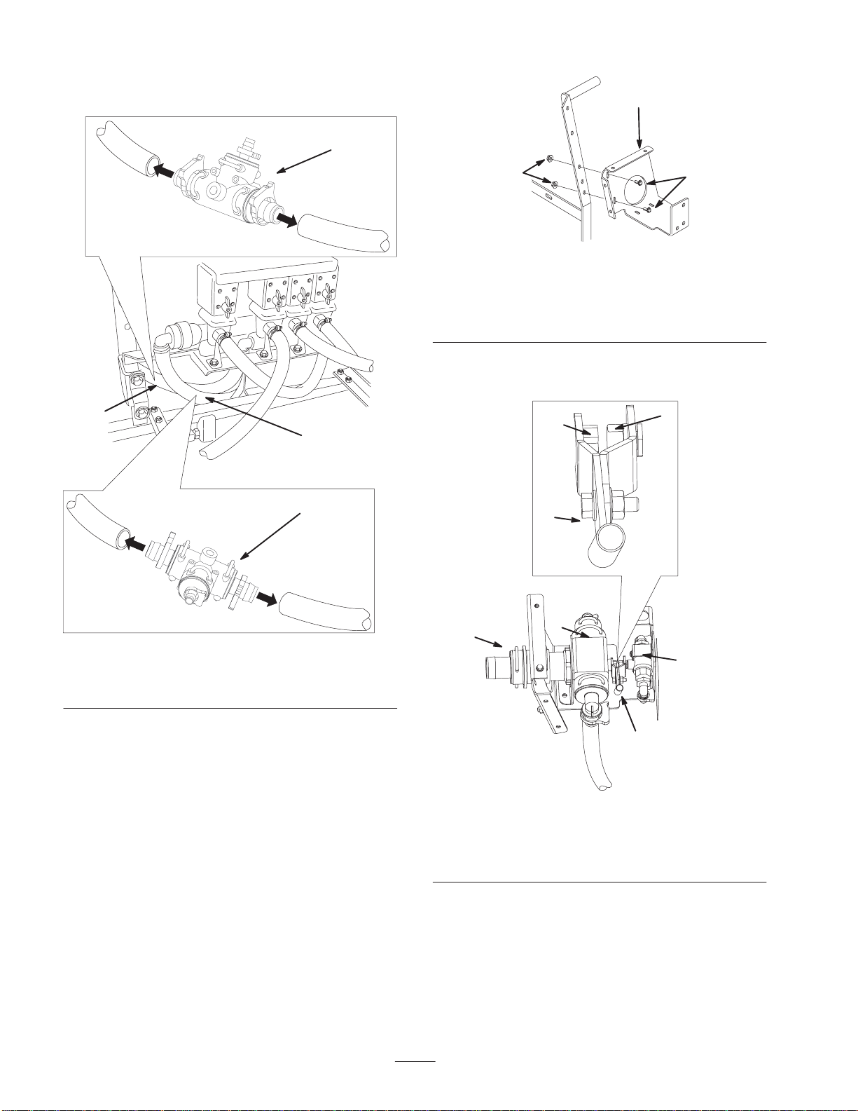
3. Connect the fitting you installed into the boom supply
hose to the control valve assembly, securing it with the
retainer you removed previously (Fig. 15).
m–6383
1
2
4
3
5
Figure 15
1. Connect the boom supply
hose to the control valve
assembly here.
2. Control valve assembly
3. Large hose
4. Connect the large hose
from the control valve
assembly to the boom
supply valves here.
5. Rubber trim
4. Install the control valve assembly onto the control box
mounting bracket (Fig. 14) using 2 flange-head bolts
(1/4 x 3/4 inch) but do not tighten the fasteners.
5. Install the small ball valve assembly to the control box
mounting bracket (Fig. 14) using 2 flange-head bolts
(1/4 x 3/4 inch) and 2 flange nuts (1/4 inch) but do not
tighten the fasteners.
6. Align the axis of the levers on each valve and the valves
(Fig. 14) You may need to loosen the hose clamps
securing the flow meter to the machine to get
everything to fit well.
7. Tighten all hardware.
8. Connect the fitting on the large hose on the control
valve assembly to the fitting on the right side of the
boom supply valves (Fig. 15).
9. Disconnect the large hose from the control valve and
look inside the valve (Fig. 15). You should see an
opening in the check ball curving up. If not, rotate the
ball until the opening is fully visible and it curves up.
10.Connect the large hose to the control valve (Fig. 15).
11. Place the rubber trim piece over the frame edge to
protect the hose (Fig. 15).
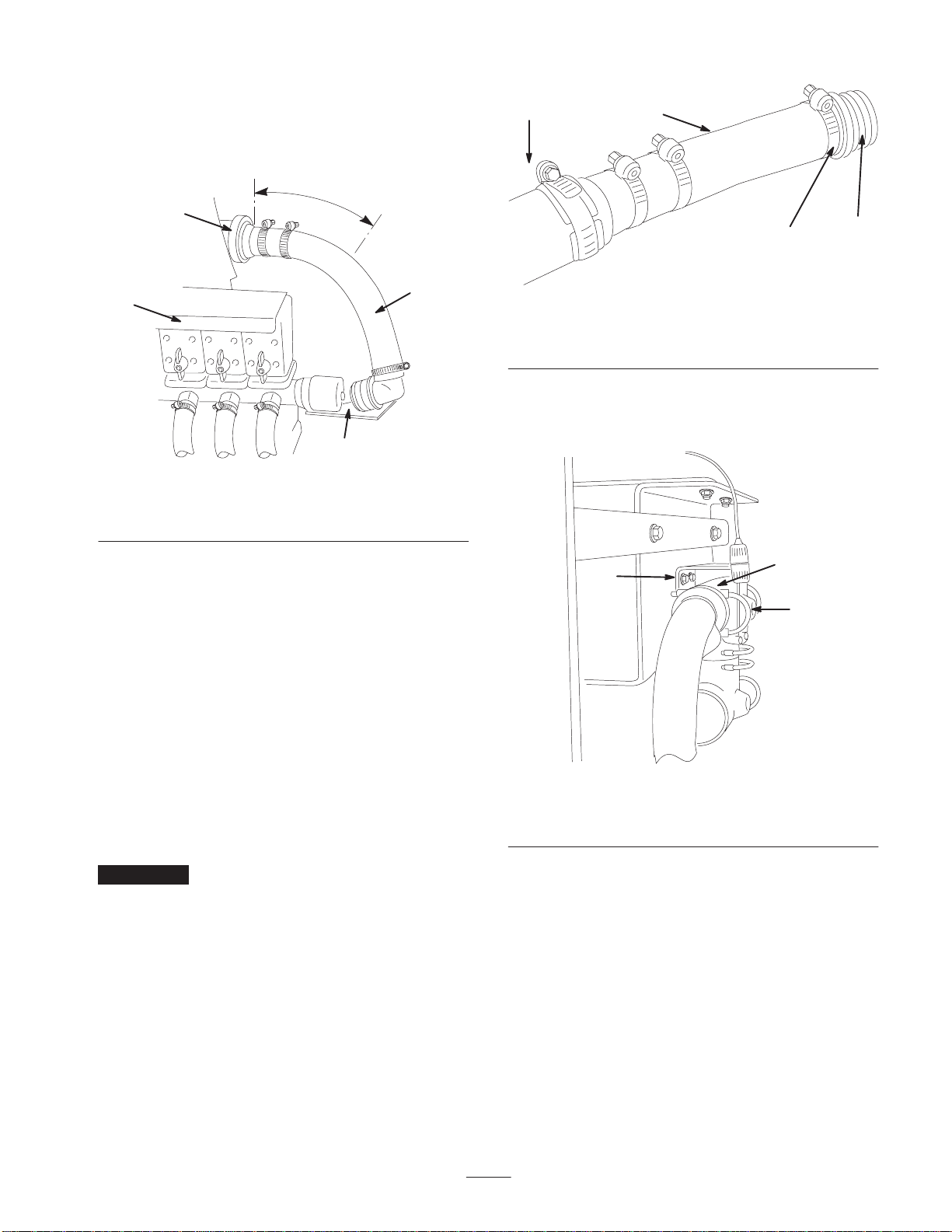
12.Connect the end of a short 1/2 inch hose to the open
fitting on the S53 tee that you installed into the agitation
hose and route it to the rear 1/2 inch barb on the small
ball valve assembly (Fig. 16).
m–6384
2
1
3
Figure 16
1. Right side of the control
box mounting bracket 2. From agitation hose
3. From by-pass hose
13.Cut the hose to the appropriate length to remove excess
slack and then connect the hose to the rear fitting.
14.Secure the hose to the fittings using 2 small plastic hose
clamps.
15.Connect the end of a short 1/2 inch hose to the open
fitting on the S53 tee that you installed into the by-pass
hose and route it to the front 1/2 inch barb on the small
ball valve assembly (Fig. 16).
16.Cut the hose to the appropriate length to remove excess
slack and then connect the hose to the front fitting.
17.Secure the hose to the fittings using 2 small plastic hose
clamps.
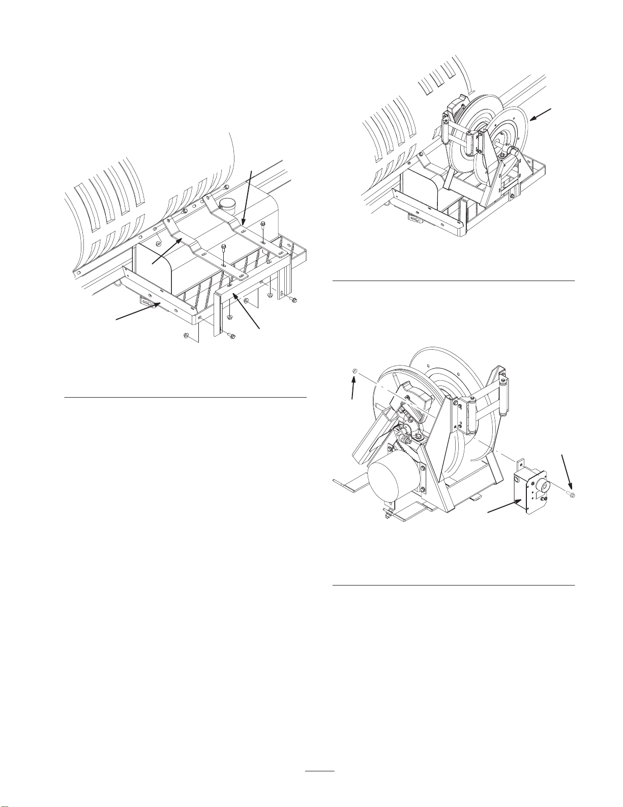
18.Wrap Teflon tape counterclockwise around the threads
of a barbed fitting (1/2 inch) and install it into the inlet
port on the side of the hose reel (Fig. 17).
m–6385
12
3
Figure 17
1. Inlet port
2. Barbed fitting, 1/2 inch 3. Hose

8
19.Connect a 1/2 inch hose to the open fitting on the
control valve assembly (Fig. 18).
m–6386
1
2
Figure 18
1. Control valve assembly 2. Hose
20.Connect the end of the hose to the fitting on the hose
reel (Fig. 17) and secure both ends with 2 small plastic
hose clamps.
Installing the Control Switches and
Pressure Gauge
1. Wrap Teflon tape counterclockwise around the threads
of the gauge and install the reducer fitting onto the
gauge (Fig. 19).
m–6387
1
2
3
4
5
Figure 19
1. Pressure gauge
2. Bracket (inside of the
control box cover)
3. Nut
4. Reducer fitting
5. Black plastic fitting
2. Install the black plastic fitting into the reducer fitting on
the gauge (Fig. 19).
3. Install the pressure gauge into the bracket under the
circular opening inside the control box cover, securing
it with the nut packaged with it (Fig. 19).
Note: The face of the gauge must face the circular opening
of the cover.
4. Wrap Teflon tape counterclockwise around the threads
of the small silver fitting that is packaged with the red
tubing and install it into the port you drilled out on the
tee in front of the boom valves (Fig. 11).
5. Install the two switches into the rectangular holes on the
top of the cover (Fig. 20). Install the momentary switch
(switch that does not stay in either position when you
are not pressing it) into the hole marked with the
continuous variable and plus (+) and minus (–) signs.
Note: The small square hole on the bottom of the switches
should be oriented toward the long slot in the cover.
m–6388
1
23
Figure 20
1. Control box cover
2. Toggle switch 3. Momentary switch

9
6. Disconnect the connectors under the dash between the
manual control box and the spray harness (Fig. 21).
m–6389
1
3
2
Figure 21
1. Existing manual control
box harness
2. Spray harness
3. T-end of the new, rear
control box harness
m–6399 1
23
4
Figure 22
1. Rear control box harness
2. T-end
3. Middle lead with eye-ring
connector and spade
connector.
4. Switch connectors
7. Connect the T-end of the new rear control box harness
between the manual control box harness and the spray
harness (Fig. 21 and 22).
8. Route the rear control box harness through the dash,
under the vehicle, through the wire harness rings, and
back to the control box (Fig. 23 and 24).
m–6394
1
Figure 23
1. Wire harness rings
m–6395
1
1
Figure 24
1. Rear control box harness routed to the control box area
9. Route the middle lead into the engine compartment and
along the front of the engine through the cable guides
securing the main wire harness.

10
10.Connect the middle lead with the spade connector to the
open lead on the fuse box under the driver’s seat
(Fig. 22 and 25).
m–6396
1
2
3
4
Figure 25
1. Middle lead with a spade
connector
2. Open position on the fuse
block
3. Middle lead with an
eye-ring connector
4. Ground terminal block
11. If necessary, install a 10 amp fuse in the position where
you connected the wire.
12.Connect the middle lead with the eye ring connector to
a ground stud on the ground terminal block (Fig. 25).
13.Connect the connector with mostly green and yellow
wires to the spray selection switch (toggle style switch)
(Fig. 26).
m–6397
2
1
4
3
Figure 26
1. Spray selection switch
2. Connector with mostly
green and yellow wires
3. Rate control switch
4. Connector with
multi-colored wires
14.Connect the connector with the multi-colored wires to
the rate control switch (momentary switch) (Fig. 26).
15.Install the switch wire cover over the switches and
around the wires (Fig. 27) and secure it with
4 flange-head bolts (1/4 x 3/4 inch) and 4 flange nuts
(1/4 inch).
m–6391
1
2
Figure 27
1. Switch wire cover 2. Wire harness
16.Connect the small red tube to the silver fitting you
installed in step 4 and the other end to the fitting on the
bottom of the pressure gauge.
17.Install the control box cover to the control box
mounting bracket (Fig. 28), using 5 flange-head bolts
(1/4 x 3/4 inch).
m–6390
2
2
1
3
2
Figure 28
1. Control box cover
2. Flange-head bolt,
1/4 x 3/4 inch
3. Knob
18.Install the knob onto the valve control lever (Fig. 28).

11
Connecting the Spray Hose
1. Wrap Teflon tape counterclockwise around the threads
of the hose fitting on the long hose and install the fitting
into the connecting tube on the reel (Fig. 29).
m–6393
Figure 29
2. Connect the free end of the long hose to the fitting on
the gun (Fig. 30).
m–6392
2
3
1
Figure 30
1. Spray gun
2. Hose fitting 3. Hose
3. Secure the end of the hose with a small plastic hose
clamp.
4. Connect the negative battery wire to the battery and
turn the ignition key to the Run position.
5. Press the hose wind button and carefully guide the hose
onto the reel.
Hands, loose clothing, long hair, and jewelry could
get caught in the hose and reel while rewinding
and cause injury.
•Keep your hands clear of the reel and hose while
it is rewinding.
•Do not wear loose clothing or jewelry and tie up
long hair.
Caution
Safety Instructions
Improper use or maintenance by the operator or owner
can result in injury. To reduce the potential for injury,
comply with these safety instructions and always pay
attention to the safety alert symbol, which means
CAUTION, WARNING, or DANGER—“personal
safety instruction.” Failure to comply with the
instruction may result in personal injury or death.
Read also the safety and operation instructions in the
vehicle Operator’s Manual.
•Do not aim the hand sprayer at any person or animal.
Fluids under high pressure can penetrate skin and cause
severe injury, possibly resulting in amputation or death.
Hot liquids and chemicals can also cause burns or
injury. If any part of the body comes in contact with the
spray stream, immediately consult a physician familiar
with injected fluid injuries.
•Do not place your hand or any other part of you body in
front of the spray nozzle.
•Do not leave the equipment under pressure when you
are not present.
•Do not use the hand sprayer if the hose, trigger lock,
nozzle, or any other part is damaged or missing.
•Do not use the hand sprayer if there are any leaks in any
hoses, fittings, or other components.
•Do not spray near power lines.
•Do not drive while spraying with a hand sprayer.
•Wear rubber gloves, safety goggles, and a full body
protective suit when spraying chemicals with the hand
sprayer.

12
Safety and Instruction Decals
Safety decals and instructions are easily visible to the operator and are located near any area
of potential danger. Replace any decal that is damaged or lost.
106-1277
1. Boom spray 2. Hand spray
106-1278
1. Boom spray
2. Hand spray
3. Continuous variable
setting
4. Increase
5. Decrease
106-1279
95-2213
87-0540

13
Operation
Fluid under pressure can penetrate skin and cause
injury.
•Keep your body and hands away from nozzles
that eject high pressure fluid.
•Do not aim the sprayer at any person or animal.
•Make sure all fluid hoses and lines are in good
condition and all connections and fittings are
tight before applying pressure to the system.
•Use cardboard or paper to find leaks.
•Safely relieve all pressure in the system before
performing any work on it.
•Get immediate medical help if fluid is injected
into skin.
•Hot liquids and chemicals can cause burns or
other harm.
Warning
Switching from Boom Spray
Mode to Hand Spray Mode
1. Stop the machine and set the parking brake.
Driving while using the hand sprayer can cause
loss of control, resulting in injury or death. Do not
operate the hand sprayer while driving.
Warning
2. Ensure that the pump switch is on and the pro control
(if applicable) is set in the manual position.
3. Set the throttle to the hand spray position.
4. Ensure that the trigger lock on the spray gun is locked.
5. Set the spray selection switch to the hand spray position
(Fig. 31).
m–6404
1
2
34
Figure 31
1. Spray selection switch
2. Rate control switch 3. Valve control lever
4. Pressure gauge
6. Move the valve control lever forward to the hand spray
position (Fig. 31).
7. Adjust the rate control switch to increase or decrease
the pressure, as read on the pressure gauge, to the
desired setting (Fig. 31).
Note: The maximum pressure is 150 psi.
Spraying with the Hand
Sprayer
1. Pull out the desired amount of hose from the reel.
2. Release the trigger lock.
3. Direct the spray gun nozzle at the area to be sprayed
and pull the trigger.
4. Release the trigger and set the trigger lock when
finished.
Switching from Hand Spray
Mode to Boom Spray Mode
1. Press the rewind button on the hose reel until only a few
feet of hose is out of the reel.

14
Hands, loose clothing, long hair, and jewelry could
get caught in the hose and reel while rewinding
and cause injury.
•Keep your hands clear of the reel and hose while
it is rewinding.
•Do not wear loose clothing or jewelry and tie up
long hair.
Caution
2. Press the rate control switch to reduce the pressure until
the pump stops.
3. Move the valve lever rearward to the boom spray
position.
4. Direct the spray gun nozzle at an area where it is safe to
spray, release the trigger lock, and pull the trigger until
all remaining fluid is out of the hose, then set the trigger
lock.
5. Set the spray selection switch to the boom spray
position.
6. Return the spray gun to the holder on the back of the
reel.

15

Table of contents
Other Toro Tools manuals