TORXUN AUTOPED 10 User manual

Autoped/ M10 APPENDIX rev 0 (09221 DRAFT) A-1
AUTOPED(TM)/ MODEL-10 OPERATOR
APPENDIX
©2021

Autoped/ M10 APPENDIX rev 0 (09221 DRAFT) A-2
TORXUN reserves the right to make changes in the products described in this manual without notice and without obligation of TORXUN to notify any
persons of any such revisions or changes. Additionally, TORXUN makes no representations or warranties with respect to this manual.
This manual is copyrighted 2021 TORXUN Vehicle Access Systems, all rights reserved.
No portion of this manual may be copied, reproduced, translated, or reduced to any electronic medium without prior written consent from TORXUN.

Autoped/ M10 APPENDIX rev 0 (09221 DRAFT) A-3
TABLE OF CONTENTS
AUTOPED OPERATOR PARTS AND COMPONENTS ……………………………….………………………………………….
A-5
SECTION I INSTALLING AUTOPED OPERATOR ON HEADERS LESS THAN 4”
...……………………………………………….
A-6
IMPORTANT INSTALLATION NOTE ………………………………………………………………………………………….
A-7
I.1 DOOR HANDING ……………………………………………………………………………………………………...…….
A-8
I.2INSTALLATION: LEFTHAND OPERATOR FOR HEADERS LESS THAN 4” IN HEIGHT …………………………
A-9
I.3 INSTALLATION: RIGHTHAND OPERATOR FOR HEADERS LESS THAN 4” IN HEIGHT ……………………….
A-10
SECTION II INSTALLING THE AUTOPED OPTIONAL POSITIVE STOP
…..………....................................................................
A-11
II.1 OPTIONAL POSITIVE STOP KIT ……………………………………........................................................................
A-12
II.2 INSTALLATION: POSITIVE STOP ASSEMBLY ………………………………………………………………………..
A-12
II.3 ADJUSTING THE POSITIVE STOP POSITION ………………………………………………………………………...
A-14
SECTION III ADJUSTING CLOSING SPRING PRELOAD ………………………………………………………………………
A-15
III. ADJUSTING THE CLOSING SPRING PRELOAD ……………………………...……………………………………….
A-16
SECTION IV MENUS AND PROGRAMMING ...…………………………………………………………………………………...
A-17
IV.1 PROGRAMMING FLOW: GUIDE CHART ………………………………………………………………………………
A-18
IV.2 MENU GLOSSARY ………………………………………………………………………………………………………..
A-18
IV.3 CONTROL UNIT LED LIGHTS …………………………………………………………………………………………..
A-19
IV.4 LCD SCREEN GLOSSARY ………………………………………………………………………………………………
A-19
IV.5 CHART FOR MENUS AND WHAT THEY DO ………………………………………………………………………….
A-19
IV.6 CHART FOR OPTIONS IN THE PARAMETER MENU: SETTINGS FOR DOOR/GATE MOVEMENT …………
A-20
IV.7 CONFIGURATION MENU OPTIONS AND DEFINITIONS ……………………………………………………………
A-22
IV.8 DOUBLE DOOR MENU CHART …………………………………………………………………………………………
A-24
IV.9 DIAGNOSTIC TABLE ……………………………………………………………………………………………………..
A-24
IV.10 CHART FOR THE REINIT MENU (DERSET BACK TO FACTORY DEFAULT) ………………………………….
A-25
IV.11 BLOCK/UNBLOCK MENU: LOCK KEYS ……………………………………………………………………………...
A-25
IV.12 TEACH MENU ……………………………………………………………………………………………………………
A-25
SECTION V TROUBLE SHOOTING AND ERROR CHARTS …………………………………………………………………...
A-26
V.1 ERROR CODE DEFINITIONS …………………………………………………………………………………………….
A-27
SECTION VI TERMINAL CONNECTIONS AND WIRING SCHEMATICS ……………………………………………………..
A-32
VI.1 TERMINAL CONNECTION CHART ……………………………………………………………………………………..
A-33

Autoped/ M10 APPENDIX rev 0 (09221 DRAFT) A-4
VI.2 WIRING SCHEMATIC DIAGRAMS ……………………………………………………………………………………...
A-35
SECTION VII SERVICE PARTS ……………………………………………………………………………………………………..
A-41
VII.1 SERVICE PARTS/COMPONENTS VISUAL GUIDE ………………………………………………………………….
A-42
VII.2 STANDARD PARTS LIST ………………………………………………………………………………………………..
A-43
VII.3 OPTIONAL PARTS LIST …………………………………………………………………………………………………
A-43
Autoped/ M10 APPENDIX rev 0 (09221 DRAFT) A-5
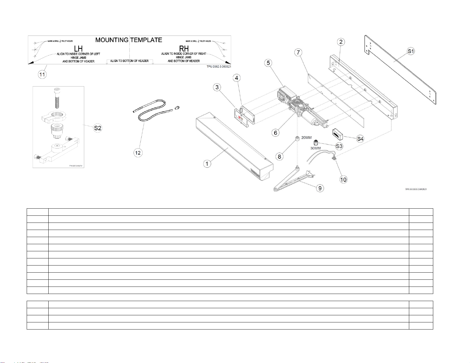
AUTOPED OPERATOR PARTS AND COMPONENTS
Item
Standard Parts Description
Qty
1
Enclosure Assembly - Front Cover
1
2
Enclosure Assembly - Rear Cover (Chassis)
1
3
Push Arm Assembly –factory assembled Lever Arm, Push Arm and Arm Shoe
1
4
Spindle Extension, 20mm
1
5
Rocker Switch
1
6
Control Unit Cover - Front and Rear
1 set
7
Drive Assembly–factory assembled motor-gearbox-controller on mounting plate
1 set
8
Drive Assembly Mounting Plate
1
9
Paper Mounting Template –for use on headers 4” or more in height or on door eaves
1
10
Rocker Switch Kit
1 set
11
Paper Mounting Template
1
12
Conduit Adapter Kit
1 set
Optional Parts Description
S1
Stiffener Plate (Optional)
(1)
S2
Positive Stop Kit (Optional)
(1)
S3
Spindle Extension, 30mm (Optional)
(1 set)
S4
Radio Frequency Activation Kit
(1)

Autoped/ M10 APPENDIX rev 0 (09221 DRAFT) A-6
SECTION I
INSTALLING AUTOPED
ON
DOOR/GATE HEADERS LESS THAN FOUR INCHES (4”)
For installation of AUTOPED Operator on headers less than four inches (4”)
in height, TORXUN requires the use of the AUTOPED StiffenerPlate or its
equivalent to add rigidity to the installation of the operator

Autoped/ M10 APPENDIX rev 0 (09221 DRAFT) A-7
IMPORTANT INSTALLATION NOTE
THE AUTOPED CAN BE USED FOR BOTH LEFTHAND OR RIGHTHAND DOOR/GATE SYSTEM WITHOUT
NEED FOR ADAPTER OR MODIFICATION
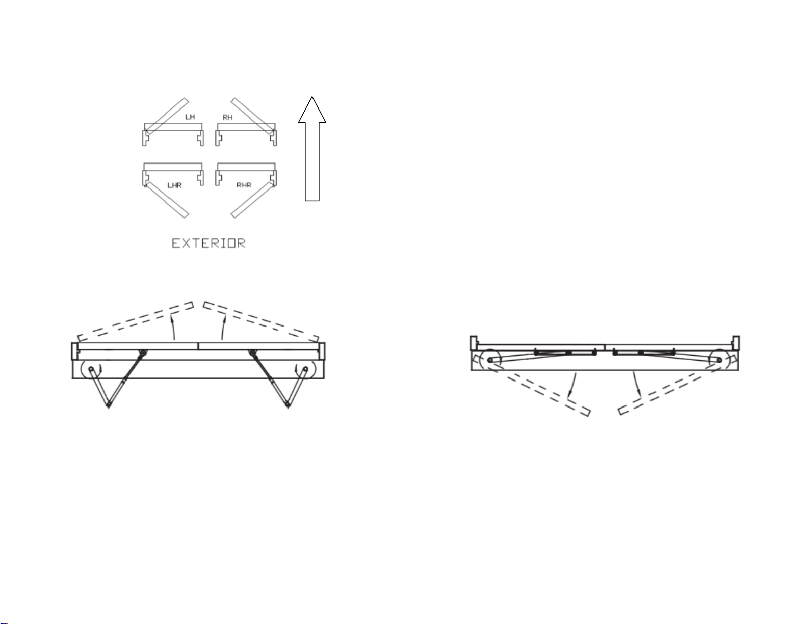
TO CHANGE HAND OF OPERATOR INSTALLATION:
FLIP THE MOTOR-DRIVE ASSEMBLY CLOCKWISE OR COUNTER-CLOCKWISE BEFORE
MOUNTING TO CHASSIS; Fig 1
CHASSIS IS NEUTRAL, ORIENTATION IS THE SAME FOR LEFT OR RIGHT HAND INSTALLATION
LEFTHAND OPERATOR INSTALLATION: CONTROL BOX UNIT IS AT LEFT OF GEAR BOX
RIGHTHAND OPERATOR INSTALLATION: CONTROL BOX UNIT IS AT RIGHT OF GEAR BOX
Fig I.1 CHANGING OPERATOR INSTALLATION: LEFTHAND TO RIGHTHAND OR VICE VERSA
Autoped/ M10 APPENDIX rev 0 (09221 DRAFT) A-8
I.1 DOOR HANDING
I.1aDefinition Door Handing
LH: Left Hand -> typically with a pull arm
RH: Right Hand -> typically with a pull arm
LHR: Left Hand Reverse -> typically with a push arm
RHR: Right Hand Reverse -> typically with a push arm
I.1bPush Application –Same Drive Unit for LHR and RHR
I.1c Pull Application –Same Drive Unit for LH and RH
Autoped/ M10 APPENDIX rev 0 (09221 DRAFT) A-9
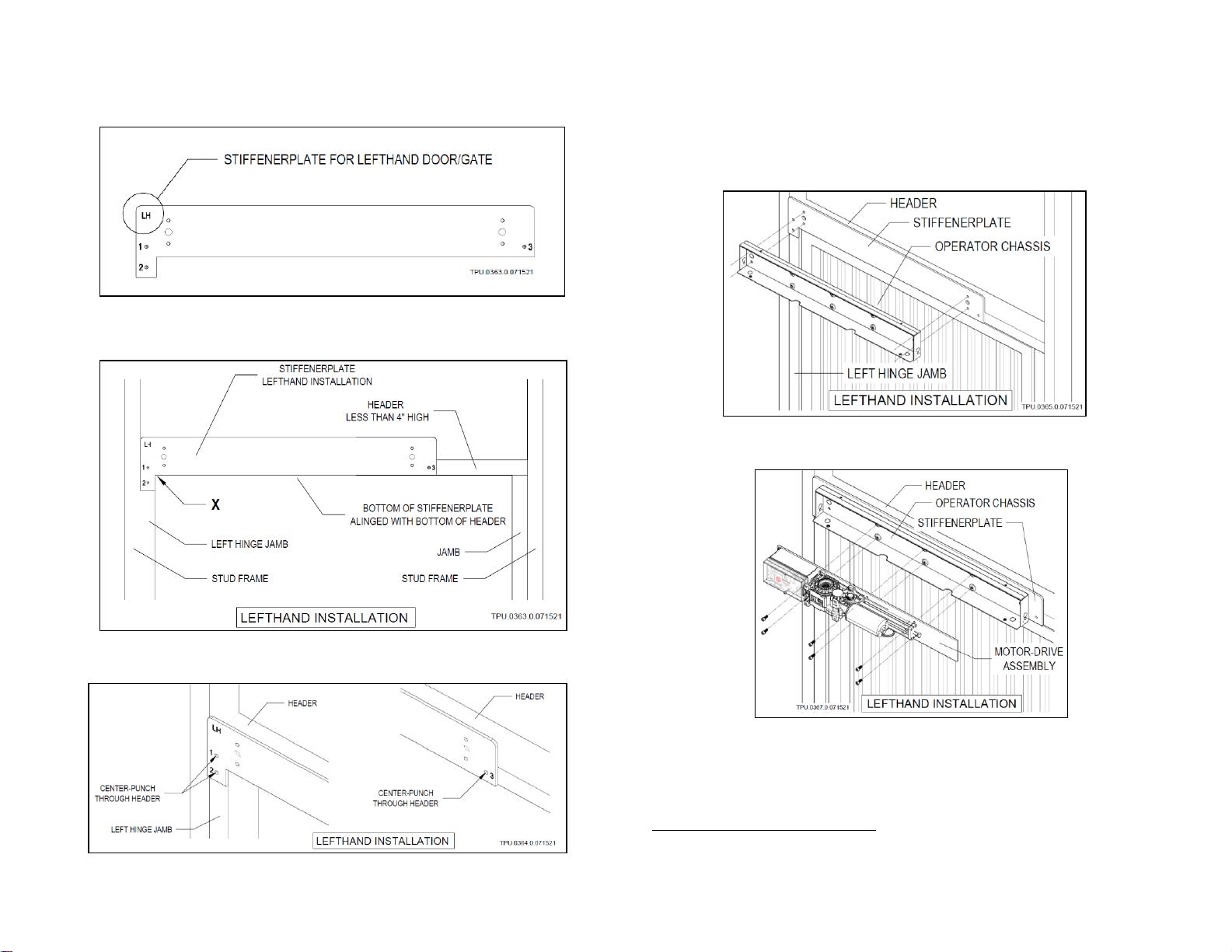
I.2 INSTALLATION: LEFTHAND OPERATOR FOR HEADERS LESS THAN 4” IN HEIGHT
STEP 1 Use StiffenerPlate for Lefthand (LH) installation
STEP 2 Align “X”to corner of left hinge jamb and bottom of
header
STEP 3 Center-punch pilot holes 1,2,3
STEP 4 Drill 1/16” pilot holes 1,2,3
STEP 5 Fasten1StiffenerPlate through holes 1,2,3
STEP 6 Mount2operator Chassis to StiffenerPlate
STEP 7 Mount3Motor-Drive assembly to operator Chassis
STEP 8 Refer back to AUTOPED Installation Manual, Section I.5
to continue installation of the Swing Arm assembly
1Type, size and material of fasteners by installer
2Use screws NF 7/16 x 20 x 3/4 included in kit to mount
3Use screws M6 x 1.0 x 12 included in kit to mount
Autoped/ M10 APPENDIX rev 0 (09221 DRAFT) A-10
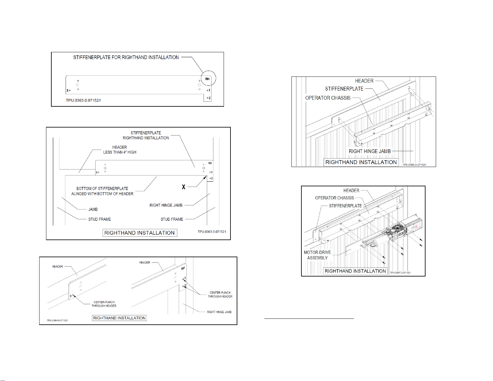
I.3 INSTALLATION: RIGHTHAND OPERATOR FOR HEADERS LESS THAN 4” IN HEIGHT
STEP 1 Use StiffenerPlate for Righthand (RH) installation
STEP 2 Align “X”to corner of right hinge jamb and bottom of
header
STEP 3 Center-punch pilot holes 1,2,3
STEP 4 Drill 1/16” pilot holes 1,2,3
STEP 5 Fasten4StiffenerPlate through holes 1,2,3
STEP 6 Mount5operator Chassis to StiffenerPlate
STEP 7 Mount6Motor-Drive assembly to operator Chassis
STEP 8 Refer back to AUTOPED Installation Manual, Section I.5
to continue installation of the Swing Arm assembly
4Type, size and material of fasteners by installer
5Use screws NF 7/16 x 20 x 3/4 included in kit to mount
6Use screws M6 x 1.0 x 12 included in kit to mount

Autoped/ M10 APPENDIX rev 0 (09221 DRAFT) A-11
SECTION II
INSTALLING THE AUTOPED
OPTIONAL POSITIVE STOP
TORXUN recommends use of the optional Positive Stop Kit when a physical stop
such as a wall, bollard, floor stop or similar items are not in place to limit the gate
or door from opening past safe limits 105º

Autoped/ M10 APPENDIX rev 0 (09221 DRAFT) A-12
II.1 OPTIONAL POSITIVE STOP KIT (P/N M10S.0040)
II.2 INSTALLING THE POSITIVE STOP
STEP 1 Swing door/gate to max opening; keep in open position.
STEP 2 Remove top two bolts on the Gear Box mounting plate
STEP 3 Install the Positive Stop Cam Bracket and Cam; use the
two stainless steel M6x3 bolts included in the kit

Autoped/ M10 APPENDIX rev 0 (09221 DRAFT) A-13
STEP 4 Gather the Spindle bolt, Positive Stop Clamp & Spindle
STEP 5 Assemble the Stop Clamp and Spindle together
STEP 6 Insert Clamp and Spindle assembly to the Gearbox
IMPORTANT NOTE ON STEP 6
Make sure that the Stop Clamp* and Stop Spindle*
are flush with each other when assembled (see
diagram*)
When placing the Stop Clamp* over the Stop
Spindle*, the door must be in the open position no
more than 105° from closed position. Place the Stop
Clamp so that its rounded vertical face (contact point)
is a hairline from making contact with the Positive
Stop Cam.
STEP 7 Insert the Spindle Bolt to the Positive Stop Clamp and
Spindle assembly; tighten to fasten the assembly to the
Gearbox
STEP 8 Go to section II.3 for Adjustment of Stop position

Autoped/ M10 APPENDIX rev 0 (09221 DRAFT) A-14
II.3 ADJUSTING THE STOP POSITION
Note: Maximum swing open position is 105º
STEP 1 Clamp the end of the Motor Shaft with a Vice Grip to
keep shaft from rotating
STEP 2 Loosen the set screw of the Positive Stop Clamp
STEP 3 Pull the Positive Stop Clamp off from the Spindle
STEP 4 Rotate the Positive Stop Clamp clockwise or
counterclockwise as needed (1~2 teeth at a time)
STEP 5 Reset the Positive Stop Clamp back on to the Spindle
STEP 6 Tighten the set screw
STEP 7 Remove grip from motor shaft, turn operator on to test
the open position of Door/Gate panel
STEP 8 If needed, repeat the preceding steps to test again
Fine adjustments of the stop position may be necessary and is
done by adjusting the Stop Cam position
STEP 9 Loosen the Positive Stop Cam Retaining Bolt
STEP 10 Rotate the Positive Stop Cam clockwise or
counterclockwise as needed
STEP 11 Tighten the Positive Stop Cam Retaining Bolt
STEP 12 Run the Operator to test the open position of Door/Gate
panel
STEP 13 If needed, repeat the preceding steps and test again

Autoped/ M10 APPENDIX rev 0 (09221 DRAFT) A-15
SECTION III
ADJUSTING
CLOSING-SPRING PRELOAD
In the process of installing the AUTOPED, the spring tension may need to be
adjusted to regulate the closing pressure of the door or gate panel. Make these
adjustments when the door or gate panel does not fully close or slams when
closing.

Autoped/ M10 APPENDIX rev 0 (09221 DRAFT) A-16
III. ADJUSTING CLOSING SPRING PRELOAD
The AUTOPED operator is equipped with a closing spring that
aids in the closure of the gate/door and to maintain closing speeds
while the gate/door is in manual mode. When power to the
operator is cut or turned off, the closing spring will allow the
Door/Gate to close in a controlled manner, fully latching the door
lock system.
The tension of the spring is responsible for regulating the amount
of pressure the door requires to be pushed open before the “Push
and Go”assist takes over.
Preload adjustment is done by turning the Adjusting Screw. By
default, distance Xbetween top of head of Adjusting Screw and
spring bracket is:
X= 1-1/32 inch (26 mm)
To adjust the Closing Spring Preload:
STEP 1 Swing Door/Gate panel open to about 60º
STEP 2 Allow panel to close on its own
STEP 3 Check to see if Door/Gate latches on full lock
STEP 4 Adjust distance Xaccording to Table II.3 (below)
STEP 5 Repeat the above steps if needed
Table II.3 Preload XValues
Door/Gate
panel width
37”
43”
49”
55”
63”
Standard push arm
Measure “X”
1-9/16”
1-7/16”
1-1/4”
1-1/16”
7/8”
Optional slide arm
Measure “X”
1-7/16”
1-5/16”
1-1/16”
3/4”
11/16”

Autoped/ M10 APPENDIX rev 0 (09221 DRAFT) A-17
SECTION IV
MENUS AND PROGRAMMING

Autoped/ M10 APPENDIX rev 0 (09221 DRAFT) A-18
IV.1 PROGRAMMING FLOW: GUIDE CHART
IV.2 MENU GLOSSARY
Display
Description
OEO
Exterior activation sensor (exterior activation signal)
OEI
Interior activation sensor (interior activation signal)
KEY
Activation device (external switch activation signal, key switch, card reader, etc.)
SES
swing side Door/Gate mounted sensor (swing side safety signal)
PRE
Header mounted sensor on swing side
SER
Push side door mounted sensor (approach side safety signal)
SEF
Door mounted sensor for obstacle detection (recycle sensitivity)
EMY-IN
Emergency open input (emergency input signal)
PUGO
Push and go

Autoped/ M10 APPENDIX rev 0 (09221 DRAFT) A-19
IV.3CONTROL UNIT LED LIGHTS
LED description and color indications
LED
Description
Indicator
SOK
System ok
Green flashing
OE active
Opening devise
Blue=active
SE active
Safety devise
Yellow=active
Error
Error
Red
E-lock relay
E-lock relay
White
IV.4 LCD SCREEN GLOSSARY
Display
Description
<REF?>
Waits for reference switch
< ?? >
Unknown
><
Closed
>##<
Closed and locked
<<>>
Opening
<>
Open
>><<
Closing
==
Stopping
IV.5 CHART FOR MENUS AND WHAT THEY DO
Menu Title
Description
Parameter
Sets the parameters for swing Door/Gate movements
CONFIG
Configuration: sets the parameters of the AUTOPED control features and functions
DOUBLE DOOR
Sets the closing sequence and interlock function
DIAGNOSTICS
Diagnostic tools that display the status of various inputs
ERROR ACTIVE
Displays pending active errors
Activate error list is updated with the latest addictions appearing at the end
A0 indicates the latest active error
HISTORY ERROR
Displays all active errors that were detected and then corrected or not corrected.
H0 indicates the latest active error
REINT
Reinitialization resets settings back to factory default
BLOCK?
Locks/unlocks joystick
UPDATE SW
Start the upgrade process from the USB stick
TEACH
Programs the initial setup, finds errors (if any)
Programs a new setup procedure when deemed necessary

Autoped/ M10 APPENDIX rev 0 (09221 DRAFT) A-20
IV.6 CHART FOR OPTIONS IN THE PARAMETER MENU: SETTINGS FOR DOOR/GATE MOVEMENT
Device
Unit type
Default
Value
Description
Region
Both
Eu
Eu or us
EU- Europe; US- united states
Software version determined by UL standards. Must be changed to
US
Vo
Low energy
9
0-9
Vc
Low energy
9
0-9
TOEx
Low energy
5s
3-60s
ANSI 156.19 for low energy: TOEx must be no less than 5 seconds
TKey
Low energy
5s
3-180s
TKey sets the hold open time resulting from an activation signal
from a device (referred to as KEY) on terminals 2+3
With TOEx and TKey, you can set a different hold open time for
different activation devices by using different terminals
TPuGo
Low energy
3s
3-180s
Determines how long the Door/Gate stays open
TDelay
Low energy
.2s
0.0-4.0s
Tdelay sets the amount of time the door hesitates to allow the lock to
release before opening.
FDelay
Low energy
Off
Off-7.0A
Fdelay is a temporary “hold closed” force applied to the door to keep it
closed while the electric lock is being released. This parameter sets
the amount of force that is applied. FDelay is only active if TDelay
setting is greater than 0.
TLock
Low energy
0.5s
0.0-4.0s
Sets amount of time Door/Gate panel will press against lock to engage
it.
Flock
Low energy
2.0A
Off-7.0A
Sets amount of force that is applied to the Door/Gate panel to engage
the lock at the closed position. It is only active if TLock setting is
greater than 0.
FSlam
Low energy
Off
Off-10
Accelerating function (Force Slam). For example: when a Door/Gate
panel needs to be forced shut due to a latch or heavy seals.
Table of contents
Popular Industrial Equipment manuals by other brands


CRH
CRH Leviat HALFEN HDB-Z Assembly instructions

ABB
ABB HT842293 Operation manual

Danfoss
Danfoss AFPA 2 / VFG 2 DN 15-250 operating guide

RINGSPANN
RINGSPANN DV 025 PFM Installation and operating instructions

Starview
Starview SSB2-1418 Original instruction manual

Siemens
Siemens SIRIUS 3RV1923 operating instructions


