Toshiba GRB200 User manual

6F2S1923 (Rev. 0.03)
Notice: This supplementary manual is issued for
Instruction manual ‘centralized Busbar Protection
IED GR200 series (GRB200C)’.
Instruction manual
Replica setting procedure
for Centralized Busbar Protection IED (GRB200)

6F2S1923 (0.03)
ii
Safety Precautions
Before using this equipment, please read this chapter carefully.
This chapter describes the safety precautions recommended when using the GR
equipment. Before installing and using the equipment, this chapter must be thoroughly read
and understood.
Explanation of symbols used
Signal words such as DANGER, WARNING, and CAUTION, will be followed by
important safety information that must be carefully reviewed.
Indicates an imminently hazardous situation which will result in
death or serious injury if you do not follow the instructions.
Indicates a potentially hazardous situation which could result in
death or serious injury if you do not follow the instructions.
CAUTION Indicates a potentially hazardous situation which if not avoided,
may result in minor injury or moderate injury or property damage.
•Current transformer circuit
Never allow the current transformer (CT) secondary circuit connected to this equipment to
be opened while the primary system is live. Opening the CT circuit will produce a
dangerously high voltage.
•Exposed terminals
Do not touch the terminals of this equipment while the power is on, as the high voltage
generated is dangerous.
•Residual voltage
Hazardous voltage can be present in the DC circuit just after switching off the DC power
supply. It takes approximately 30 seconds for the voltage to discharge.
•Fiber optic
CLASS 1 LASER PRODUCT.
DANGER
WARNING
DANGER
WARNING

6F2S1923 (0.03)
iii
CAUTION
•Earth
The earthing terminal of the equipment must be securely earthed.
CAUTION
•Operating environment
The equipment must only be used within the range of ambient temperature, humidity and
dust detailed in the specification and in an environment free of abnormal vibration.
•Ratings
Before applying AC voltage and current or the DC power supply to the equipment, check
that they conform to the equipment ratings.
•Printed circuit board
Do not attach and remove printed circuit boards when the DC power to the equipment is
on, as this may cause the equipment to malfunction.
•External circuit
When connecting the output contacts of the equipment to an external circuit, carefully
check the supply voltage used in order to prevent the connected circuit from overheating.
•Connection cable
Carefully handle the connection cable without applying excessive force.
•Modification
Do not modify this equipment, as this may cause the equipment to malfunction.
•Short-wire (Short-bar)
Do not remove the short-wire/short-bar(s) connected to the frame earth (FG) at the terminal
block on the rear of cases.
•Electric wire between #35 - #37 on the power-supply terminal block
Make sure the wire is connected.
(Exception: This wire needs to be detached for performing the dielectric voltage test.)

6F2S1923 (0.03)
iv
•Disposal
This equipment contains neither expendable supplies nor parts that can be recycled. When
disposing of this equipment, the customer must contact an operator responsible for
industrial waste disposal, and request that the operator dispose of this equipment in
accordance with the local waste disposal regulations; otherwise the person who disposes
of this equipment may be punished under local regulations. When disposing of this
equipment is practiced by the customer acting on their own behalf, it must be done so in a
safe manner according to local regulations. For further information in terms of the disposal,
the customer shall contact to a local dealer and sales staff at Toshiba Energy Systems &
Solutions Corporation (Toshiba ESS, Japan).
This equipment contains neither expendable supplies nor recyclables.
•Plastics material
This equipment contains the following plastics material.
- ABS, Polycarbonate, Acrylic resins, Nylon 66, and others.
Equipment installation and operation
•Equipment installation
Never remove cables at frame ground terminals (FGs) while the AC/DC power supplies.
•Equipment operation
The user shall have responsibilities to use and install the equipment where the
specifications are designated by the manufacture. Never operate the equipment on the
condition where the manufacture cannot intend. Otherwise, the safety function furnished
into the equipment may not be operated properly.
•Symbols
Symbol
Description
Protective conductor terminal
Caution, risk of electric shock

6F2S1923 (0.03)
v
Liability, copyright and others
•Disclaimer of liability
We have checked the description of this manual against the hardware and software
described, but we cannot guarantee that all deviations have been eliminated from the
description completely; hence, no liability can be accepted for any errors or omissions
contained in the information given. We review the information in this manual regularly
and there will be some corrections in subsequent editions. We reserve the right to make
technical improvements without notice.
•Copyright
© Toshiba Energy Systems & Solutions Corporation 2021.
All rights reserved.
•Registered Trademarks
Product/Equipment names (mentioned herein) may be trademarks of their respective
companies.

6F2S1923 (0.03)
vi
Contents
1Introduction ......................................................................................................................................... 1
2Setting .................................................................................................................................................. 2
Setting Replica.............................................................................................................................. 2
2.1.1 Setting CH use....................................................................................................................... 2
2.1.2 Setting CH1-POS................................................................................................................. 12
Setting Hardware definition ...................................................................................................... 14
2.2.1 SubUnit structuring ............................................................................................................ 14
2.2.2 BI Definition settings .......................................................................................................... 15
3Setting procedures ............................................................................................................................. 19
Step1: Use settings [CH use_CH*] ............................................................................................ 19
Step2: Name settings [CH name_CH*] ..................................................................................... 20
Step3: Device settings [BayDevice_CH*, Coupler No_CH*]..................................................... 21
Step4: Structure settings [Zone_CH*], etc. ............................................................................. 22
3.4.1 Step4-0:Zone definitions...................................................................................................... 22
3.4.2 Step4-1:Feeder definitions .................................................................................................. 22
3.4.3 Step4-2:Coupler definitions ................................................................................................ 23
3.4.4 Step4-3:Defining CHs for Non-used ................................................................................... 24
Step5: Zero ampere settings [ZACbyCB_CH*].......................................................................... 25
4Setting items...................................................................................................................................... 26
Settings ....................................................................................................................................... 26
Signals......................................................................................................................................... 30
Appendixes ................................................................................................................................................ 54
Feeder models .................................................................................................................................... 55
Bus coupler models ............................................................................................................................ 58
End-section model.............................................................................................................................. 62

6F2S1923 (0.03)
GRB200C (Replica)
-1-
1 Introduction
In order that a busbar is protected, the user must implement within it the busbar topology of
the substation to which it is to be applied. GRB200 relay operates using a check-zone-
protection zone (DIFCH) and discriminating-zone-protection zones (DIFZA, DIFZB etc.). The
DIFCH zone provides an overall protection for the entire busbar, whilst the DIFZA, DIFZB etc.
zones provide individual protection zones for discrete busbar sections. The zones are protected
based on the differential protection principle (DIF; derived from Kirchhoff’s law).
Busbar transformation does not affect the DIFCH zone protection because the sum of all
of the currents flowing in the busbar is zero regardless of the transformation. On the other
hand, busbar transformation may affect DIFZA, DIFZB etc. zone protections because they
operation for individual one. The zone could vary through busbar transition. The replica
feature is able to follow the busbar transition when the ‘Open’or ‘Closed’position signals are
given with the substation circuit breakers (CBs) and disconnectors (DSs). Thus, the DIFZA,
DIFZB etc. zones are able to follow the busbar transition so that the protection can work
correctly.
The replica feature duplicates the currents flowing in respective discriminating-zone-
protection zones; it is required for the user to have settings for respective channels (CHs).
Busbar topology and operation can be duplicated by Replica with 24 CHs.
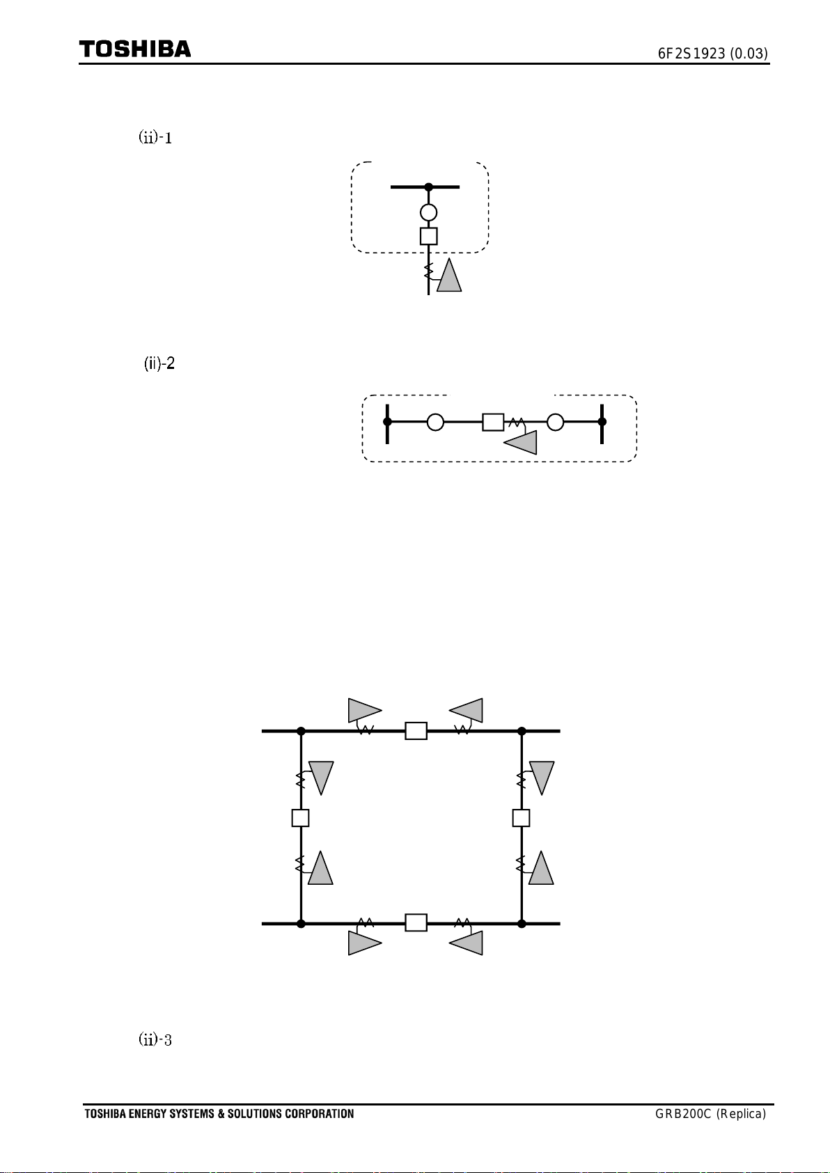
A CH can correspond with a feeder. The CH can have three protection zones or less:
Zone1, Zone2, and Zone3. A protection zone (DIFZ*) corresponds with a protection
zone (Zone*) on one-to-one basis.
A CH can correspond with a bus coupler. Forward Zone1/Zone2/Zone3 and Reverse
ZoneR1 are ready to protection. A protection zone (DIFZ*) is assigned to a protection
zone (Zone*) on one-to-one basis.
CT inputs are for current information about flowing-in and flowing-out in each zone.
During a particular operational condition such that a bus-coupler circuit breaker is
opened, if the protection zone does not require current information, Zero ampere
control is invoked so that the current is not relevant to the differential calculation
─────────────────────────────────────────────────────────────────
Note: The contents discussed herein are based on an understanding of the principle of
operation of the GRB200 relay that are described in a separate Instruction
manual entitled “
Centralized Busbar Protection IED GR200 series (GRB200).”

6F2S1923 (0.03)
GRB200C (Replica)
-2-
2 Setting
Setting Replica
2.1.1 Setting CH use
Four setting categories are in each CH setting:
(i) CH name (CH name_CH*)
(ii) Bay arrangements (BayDevice_CH*, CouplerNo_CH*)
(iii) Bay structures (Zone1_CH*, etc.)
(iv) Zero ampere control (ZACbyCB_CH*).
Figure 2.1-1 illustrates how to set the bay structures using [CH_use_CH*]. To start, the user
needs to set On for every [CH use_CH*].
CH1
10:48 1/18
CHname_CH1
Preferred CH1 name
Common
10:48 1/4
Misc. >
CH_Exclusion >
Replica >
H/W Definition >
ZACbyCB_CH* +
Off
BayDevice_CH1 +
Non
CouplerNo._CH1 +
1
Zone1_CH1 +
Non
Zone2_CH1 +
Non
Zone3_CH1 +
Non
ZoneR1_CH1 +
Non
Zone-NoDIF_CH1 +
Non
CB_CH1 +
Non
DS11_CH1 +
Non
DS12_CH1 +
Non
DS13_CH1 +
Non
DS21_CH1 +
Non
Line1_CH1 +
Non
Line2_CH1 +
Non
Line3_CH1 +
Non
CT-POS_CH1 +
Pos1
Replica
10:48 1/25
CH1-POS +
BIO#6
CH use_CH1 +>
On
CH use_CH2 +>
Off
CH use_CH3 +>
Off
CH use_CH24 +>
Off
CH2
CH3
CH24
10:48 1/18
CHname_CH24
Preferred CH24 name
CH Name
Bay arrangement
Zero ampere control
Bay structure
Switches for CH1 to CH24
Figure 2.1-1 Setting structures in CH use_CH1 to 24
Table 2.1-1 CH use settings
Setting items
Range
Unit
Contents
Default
CH use_CH*
Off / On
–
CH use definition
Off

6F2S1923 (0.03)
GRB200C (Replica)
-3-
(i) CH name
Settings [CH name_CH*] are provided in order that the user can easily identify the bay and
channel information on the HMI screen. The user can enter preferred CH names using GR-
TIEMS. Figure 2.1-2 shows the preferred names are displayed on Metering, Fault values of
Recording, and Replica Settings.
Fault Record#1
10:48 */***
CH1
Preferred Bay name
Ia
****.**kA ***.*deg
Ib
****.**kA ***.*deg
Ic
****.**kA ***.*deg
I1
****.**kA ***.*deg
I2
****.**kA ***.*deg
I0
****.**kA ***.*deg
CH2
Preferred Bay name
Ia
****.**kA ***.*deg
Ib
****.**kA ***.*deg
Ic
****.**kA ***.*deg
I1
****.**kA ***.*deg
I2
****.**kA ***.*deg
I0
****.**kA ***.*deg
CH24
Preferred Bay name
Ia
****.**kA ***.*deg
Metering
10:48 */***
CH1
Preferred Bay name
Ia
****.**kA ***.*deg
Ib
****.**kA ***.*deg
Ic
****.**kA ***.*deg
I1
****.**kA ***.*deg
I2
****.**kA ***.*deg
I0
****.**kA ***.*deg
CH2
Preferred Bay name
Ia
****.**kA ***.*deg
Ib
****.**kA ***.*deg
Ic
****.**kA ***.*deg
I1
****.**kA ***.*deg
I2
****.**kA ***.*deg
I0
****.**kA ***.*deg
CH24
Preferred Bay name
Ia
****.**kA ***.*deg
Metering screen
Recording screen
CH1
10:48 */*
CHname_CH1
Preferred Bay name
BayDevice_CH1 +
Non
CouplerNo._CH1 +
1
ZACbyCB_CH* +
Off
CH use screen
Same ‘Bay name for CH1’displayed
CH1
Same ‘Bay name for CH2’displayed
Same ‘Bay name for CH24’displayed
CH2
CH24
Figure 2.1-2 CH names entered are displayed on Metering/Recording/CH use
Table 2.1-2 CH name settings
Setting items
Range
Unit
Contents
Default
CH name_CH*
[14 letters or less]
–
Preferred Bay name
(Absent)
Note: It is recommended for the user to enter ‘Bay names’for these settings.
(ii) Bay arrangement
The bay devices can be activated with CH settings, but the user needs to set a type of bay
devices with setting [BayDevice_CH*]. The below figures illustrate how to choose a bay type

6F2S1923 (0.03)
GRB200C (Replica)
-4-
among (i) to (iv), when CH1 is accounted in Replica.
[BayDevice_CH*]=Feeder: set ‘
feeder type
’when the bay is formed below:
CH1
Busbar 1
Protection zone
Figure 2.1-3 Feeder setting when CH1 used
[BayDevice_CH*]=Coupler: set ‘
coupler type
’when the bay is formed below.
Busbar 2
Busbar 1
Protection zone
CH1
Figure 2.1-4 Coupler setting when CH1 used
For the coupler type, it is required for the user to enter a coupler number for
setting [Coupler No_CH*]. Remind that the same number must be entered on
both sides of the coupler, when two CHs are assigned for it. Figure 2.1-5
illustrates an example that the same coupler number ‘1’is set for CH1 and CH2;
similar means is employed for the other settings. As there is no rule for
numbering the CHs, so it is possible to choose preferred numbers for the CHs.
DS closed
DS open
CB closed
CB open
Forward looking BU
(looking in left)
CT
CB/DS wirings
Optical cables
CH1
[Coupler No.8_CH]=4
CH2
Busbar1
Busbar2
CH3
CH4
4
CH6
CH5
CH8
CH7
Busbar4
Busbar3
[Coupler No._CH7]=4
[Coupler No._CH3]=2
[Coupler No._CH4]=2
[Coupler No._CH2]=1
[Coupler No._CH1]=1
[Coupler No._CH6]=3
[Coupler No._CH5]=3
Coupler3
Coupler1
Coupler2
Coupler4
Figure 2.1-5 Coupler number settings
[BayDevice_CH*]=EndSection: set ‘
end-section type
’when the user wishes
terminating a protection zone on the middle, as shown the below:

6F2S1923 (0.03)
GRB200C (Replica)
-5-
Busbar 2
Busbar 1
Protection zone
CH1
Figure 2.1-6 EndSection when CH1 is used
[BayDevice_CH*]=Non: when other CHs is not to be employed in the busbar ,
set Non.
Table 2.1-3 Bay arrangement settings
Setting items
Range
Unit
Contents
Default
BayDevice_CH*
Non / Feeder / Coupler / EndSection
-
Bay device selection
Non
Coupler No_CH*
1 –8
-
Coupler No. definition
1
Note: As the setting [Coupler No_CH*] has a default number, it is not required for the
user to enter the number, when Non, Feeder, or EndSection is set for the
[BayDevice_CH*].

6F2S1923 (0.03)
GRB200C (Replica)
-6-
(iii) Protection zones and Bay structure
A Bay structure has been arranged with the setting [BayDevice_CH*] so that a DIF zone
calculation (ZoneA/B/C/D/E/F) can be corresponded with a protection zone (Zone1/2/3/R1) on
one-to-one basis in each CH. Table 2.1-4 shows the settings for zones and structures; they are
provided in each CH. The setting meanings are described below.
Table 2.1-4 Setting items in Bay structure
Setting items
Range
Unit
Contents
Default
Zone1_CH*
Non / ZoneA /
ZoneB / ZoneC /
ZoneD / ZoneE /
ZoneF
–
Forward 1st protection zone definition
Non
Zone2_CH*
Forward 2nd protection zone definition
Non
Zone3_CH*
Forward 3rd protection zone definition
Non
ZoneR1_CH*
Reverse 1st protection zone definition
Non
Zone-NoDIF_CH*
CH’s current is unused in DIF zone calculation.
Non
CB_CH*
Non / NO / NC /
Both / DirConn
–
CB definition
Non
DS11_CH*
DS11 definition
Non
DS12_CH*
DS12 definition
Non
DS13_CH*
DS13 definition
Non
DS21_CH*
DS21 definition
Non
Line1_CH*
Non / Exist
–
Line1 definition
Non
Line2_CH*
Line2 definition
Non
Line3_CH*
Line3 definition
Non
CT-POS_CH*
POS1 / POS2
–
CT position
POS1
ZACbyCB_CH*
Off / On
–
‘Zero-ampere’controlled with CB condition
Off
Settings [Zone1_CH*], [Zone2_CH*], and [Zone3_CH*]
Using these settings [Zone_CH*], the forward-looking protection is available by choosing
a zone among ZoneA to ZoneF (Non must be set when it is unused). They are available for
feeder, coupler, and end-section (see (iii)-1, (iii)-2, and (iii)-3 ).
Setting [ZoneR1_CH*]
The revers-looking protection is available when a CH is positioned on a coupler (see (iii)-
2). The CH can have bi-directional protection zones with the settings [Zone_CH*].
Setting [Zone-NoDIF_CH*]
The setting [Zone-NoDIF_CH*] allows the DIF calculation not to take the CH current
information from the CH if required. Figure 2.1-7 illustrates that the DIF calculation will
not take CH2 information by this (setting [Zone-NoDIF_CH2]=ZoneC). The figure shows
that the busbar has a transfer bus (i.e., ZoneC). The CH2 stands at the edge of the
protection zone such that ZoneB or ZoneC will be protected. However, CH5, designed to
protect ZoneA and ZoneB, does not stand at the opposite of the CH2. In other words, the

6F2S1923 (0.03)
GRB200C (Replica)
-7-
DIF calculation cannot be achieved in the below case; hence, it is required for the user to
set [Zone-NoDIF_CH2]=ZoneC.
Zone C
Zone B
Zone A
CH1
CH2
CH3
CT2
CH4
CH5
: DS closed
: DS open
: CB closed
: CB open
Feeder1
Feeder2
Feeder3
Coupler
1
CT5
Figure 2.1-7 Example of disqualifying DIF calculation of ZoneC
Setting [CB_CH*]
The user can define the absences or existence of CB on the bay structure by the setting; it
is also possible to define that the form of the CB auxiliary contacts are injected to GRB200.
The form is defined by selecting ‘Normally-Open (Form A)’, ‘Normally-Closed (Form B)’, or
‘Both NO and NC (Form C)’:
NO: is used when CB is existence; the CB is described with a NO.
NC: is used when CB is existence, the CB is described with a NC.
Both: is used when CB is existence; the CB is described with both NO and NC.
Non: is used when CB is absent; the CB is not connected with the line.
DirConn: can be applied for below cases:
CB is existence, but a CH does not need to get the state of the contact.
CB is absence, but a CH needs to have the CB hypothetically.
Settings [DS11_CH*], [DS12_CH*], [DS13_CH*], [DS21_CH*]
Similar to the CS, the user can define the absences or existence of DS with the settings.
The user can also select an option among Non, NO, NC, Both, and DirConn.
Settings [Line1_CH*], [Line2_CH*], [Line3_CH*]
Bay structure can be mimicked with single line diagrams using setting [Line_CH*].
Non: is set when single line diagrams do not have a line.
Exist: is set when single line diagrams have a line.
Setting [CT-POS_CH*]
When a CT is equipped in the feeder, the user can define the CT position on the bay
structure. The user can select either POS1or POS2options

6F2S1923 (0.03)
GRB200C (Replica)
-8-
Setting [ZACbyCH_CH*]
The setting is for Zero-ampere control. By this control, the value of flowing current will be
set ‘Zero’unconditionally, when the CB is open in the CH. This control can operate when
On is set for the setting [ZACbyCH_CH*]. On the other hand, set Off when this is not
required. Remind that the user has to set either NO, NC, or Both for the setting [CB_CH*]
in order for this control.
[BayDevice_CH*]=Feeder:
Figure 2.1-8 illustrates Bay structure diagram about Feeder.
The user has to have settings: [Zone1], [Zone2], [Zone3], [DS11], [DS12], [DS13],
[DS21], [CB], [Line1], [Line2], and [CT-Pos]. The settings allow the user construct the
bay structure, which will be identical to a feeder bay drawn in Single line diagram.
Table 2.1-5 shows applicable settings in the feeder.
Table 2.1-5 Applicable setting in Feeder
Figure 2.1-8 Bay structure diagram
of feeder
Setting items
Applicable setting
(Xmeans applicable)
Zone1_CH*
X
Zone2_CH*
X
Zone3_CH*
X
ZoneR1_CH*
--
Zone-NoDIF_CH*
X
CB_CH*
X
DS11_CH*
X
DS12_CH*
X
DS13_CH*
X
DS21_CH*
X
Line1_CH*
X
Line2_CH*
X
Line3_CH*
X
CT-Pos_CH*
X
ZACbyCB_CH*
X
Zone1
CB
[CT-Pos]=Pos1
[CT-Pos]=Pos2
DS
11
DS
12
DS
13
DS
21
Line1
Line2
Line3
Zone2
Zone3

6F2S1923 (0.03)
GRB200C (Replica)
-9-
[BayDevice_CH*]=Coupler:
Figure 2.1-9 illustrates Bay structure diagram about Coupler.
The user has to have settings: [Zone1], [Zone2], [Zone3], [ZoneR1], [DS11], [DS12],
[DS13], [DS21], and [CB]. The settings allow the user construct the bay structure,
which will be identical to a coupler bay drawn in Single line diagram.
Table 2.1-6 shows applicable settings in the coupler.
Table 2.1-6 Applicable setting in Coupler
Figure 2.1-9 Bay structure
diagram of Coupler
Two CHs are generally assigned at a coupler or a section, whereas it is also possible
to assign a single CH at the coupler or the section. Settings samples, shown in the
next, illustrate a case of two CHs assignment and a case of single CH assignment:
Setting items
Applicable setting
(Xmeans applicable)
Zone1_CH*
X
Zone2_CH*
X
Zone3_CH*
X
ZoneR1_CH*
X
Zone-NoDIF_CH*
X
CB_CH*
X
DS11_CH*
X
DS12_CH*
X
DS13_CH*
X
DS21_CH*
X
Line1_CH*
--
Line2_CH*
--
Line3_CH*
--
CT-Pos_CH*
--
ZACbyCB_CH*
X
DS
11
DS
12
DS
13
CB
DS
21
Zone1
Zone2
Zone3
ZoneR1

6F2S1923 (0.03)
GRB200C (Replica)
-10 -
<Case: Two CHs assigned at coupler/section>
Figure 2.1-10 illustrates the case about two CHs (CHn and CHm) assignment.
Area is divided by two CHs: CHm area and CHn area. Remind that CH settings are
required for the both, as show in Figure 2.1-11.
Figure 2.1-10 Example of two CHs
assignment
Figure 2.1-11 Covered area and settings
<Case: Single CH assigned at coupler/section>
Figure 2.1-13 illustrates the case about single CH assignment.
The user has to have forward settings and reverse setting carefully with the
consideration of CT polarity.
Figure 2.1-12 Settings in single CH
assignment
Figure 2.1-13 Example of
single CH assignment
DS
-A
CB
DS
-B
Busbar-A
Busbar-B
CH
m
n
CH
DS
-A
CB
DS
-B
Busbar-A
Busbar-B
DS
-A
CB
Busbar-A
n
CH
Area covered by CHn
Setting item
Setting of CHn
Zone1_CH* X
Zone2_CH*
Non
Zone3_CH*
Non
ZoneR1_CH* Non
Zone-NoDIF_CH*
Non
CB_CH*
X
DS11_CH*
X
DS12_CH*
Non
DS13_CH*
Non
DS21_CH*
Non
Line1_CH*
--
Line2_CH*
--
Line3_CH*
--
CT-Pos_CH*
--
ZACbyCB_CH*
X
Area covered by CHm
Setting item
Setting of CHn
Zone1_CH* X
Zone2_CH*
Non
Zone3_CH*
Non
ZoneR1_CH* Non
Zone-NoDIF_CH*
Non
CB_CH*
X
DS11_CH*
X
DS12_CH*
Non
DS13_CH*
Non
DS21_CH*
Non
Line1_CH*
--
Line2_CH*
--
Line3_CH*
--
CT-Pos_CH*
--
ZACbyCB_CH*
X
CB
DS
-B
Busbar-B
CH
m
Setting item
Setting
Zone1_CH* X
Zone2_CH*
Non
Zone3_CH*
Non
ZoneR1_CH* X
Zone-NoDIF_CH*
Non
CB_CH*
X
DS11_CH*
X
DS12_CH*
Non
DS13_CH*
Non
DS21_CH*
X
Line1_CH*
--
Line2_CH*
--
Line3_CH*
--
CT-Pos_CH*
--
ZACbyCB_CH*
X
DS
-A
CB
DS
-B
Busbar-A
Busbar-B
Forward
Reverse

6F2S1923 (0.03)
GRB200C (Replica)
-11 -
[BayDevice_CH*]=EndSection:
Figure 2.1-14 illustrates Bay structure diagram about EndSection.
The user has to have settings: [Zone1], [DS11], [DS21], and [CB]. The settings allow
the user construct the bay structure, which will be identical to Section End drawn in
Single line diagram.
Table 2.1-7 shows applicable settings in the End Section.
Table 2.1-7 Applicable setting in EndSection
Figure 2.1-14 Bay structure
diagram of EndSection
Setting items
Applicable setting
(Xmeans applicable)
Zone1_CH*
X
Zone2_CH*
--
Zone3_CH*
--
ZoneR1_CH*
--
Zone-NoDIF_CH*
X
CB_CH*
X
DS11_CH*
X
DS12_CH*
--
DS13_CH*
--
DS21_CH*
X
Line1_CH*
--
Line2_CH*
--
Line3_CH*
--
CT-Pos_CH*
--
ZACbyCB_CH*
X
DS
11
CB
DS
21
Zone1

6F2S1923 (0.03)
GRB200C (Replica)
-12 -
2.1.2 Setting CH1-POS
MainUnit and SubUnits have Binary IO modules (BIOs). Each BIO must be corresponded with
a CH based on one-to-one arrangement. For the correspondence, the BIO for CH1 can be
corresponded with setting [CH1-POS]; the others BIOs for CH2, CH3, etc. are corresponded on
the right hand of the CH1 automatically, when the [CH1-POS] is set.
Incidentally, the [CH1-POS] has default setting (see Table 2.1-8). Hence, the user is not
required to set (Figure 2.1-15). However, the user can change the correspondence by the setting,
if it is required (Figure 2.1-16).
Table 2.1-8 CH1-POS setting
Setting item
Range
Unit
Contents
Default
CH1-POS
BIO#1 / BIO#2 / BIO#3 /
BIO#4 / BIO#5 / BIO#6 /
BIO#7 / BIO#8
–
Start position of CH1's BIO
BIO#6
(i) Setting [CH1-POS]=BIO#6 (default set)
Figure 2.1-15 shows the BIO and the CH correspondences when the [CH1-POS] has default
BIO#6 setting.
BO1 A
BO10
21
22
BO1(SF)
1
2
BO2(SF)
3
4
BO3(SF)
5
6
BO4(SF)
7
8
BO5(SF)
9
10
BO6(SF)
11
12
BO7
13
14
BO8
15
16
BO9
17
18
BO11
23
24
BO12
25
26
BO13
27
28
BO14
29
30
BO15
31
32
BO16
33
34
BO17
35
36
BO18
37
38
BI1 A
1
2
BI1
(+)
(
-
)
3
4
BI2
(+)
(
-
)
5
6
BI3
(+)
(
-
)
7
8
BI4
(+)
(
-
)
9
10
BI5
(+)
(
-
)
13
14
BI7
(+)
(
-
)
11
12
BI6
(+)
(
-
)
15
16
BI8
(+)
(
-
)
17
18
BI9
(+)
(
-
)
21
22
2¥¥
BI10
(+)
(
-
)
23
24
BI11
(+)
(
-
)
25
26
BI12
(+)
(
-
)
27
28
BI13
(+)
(
-
)
29
30
BI14
(+)
(
-
)
31
32
BI15
(+)
(
-
)
35
36
BI17
(+)
(
-
)
33
34
BI16
(+)
(
-
)
37
38
BI18
(+)
(
-
)
BIO5 A
BO3(SF)
21
22
BO4(SF)
23
24
BO5(SF)
25
26
BO6(SF)
27
28
BO7(SF)
29
30
BO8(SF)
31
32
36
38
35
37
BO9
1
2
BI1
(+)
(
-
)
3
4
BI2
(+)
(
-
)
5
(+)
BI3
6
(+)
BI4
8
(+)
BI5
9
(+)
BI6
7
(-)
10
(-)
11
(+)
BI7
12
(+)
BI8
13
(+)
BI9
14
(-)
BO1
15
16
BO2
17
18
BIO5 A
BO3(SF)
21
22
BO4(SF)
23
24
BO5(SF)
25
26
BO6(SF)
27
28
BO7(SF)
29
30
BO8(SF)
31
32
36
38
35
37
BO9
1
2
BI1
(+)
(
-
)
3
4
BI2
(+)
(
-
)
5
(+)
BI3
6
(+)
BI4
8
(+)
BI5
9
(+)
BI6
7
(-)
10
(-)
11
(+)
BI7
12
(+)
BI8
13
(+)
BI9
14
(-)
BO1
15
16
BO2
17
18
BIO5 A
BO3(SF)
21
22
BO4(SF)
23
24
BO5(SF)
25
26
BO6(SF)
27
28
BO7(SF)
29
30
BO8(SF)
31
32
36
38
35
37
BO9
1
2
BI1
(+)
(
-
)
3
4
BI2
(+)
(
-
)
5
(+)
BI3
6
(+)
BI4
8
(+)
BI5
9
(+)
BI6
7
(-)
10
(-)
11
(+)
BI7
12
(+)
BI8
13
(+)
BI9
14
(-)
BO1
15
16
BO2
17
18
BIO5 A
BO3(SF)
21
22
BO4(SF)
23
24
BO5(SF)
25
26
BO6(SF)
27
28
BO7(SF)
29
30
BO8(SF)
31
32
36
38
35
37
BO9
1
2
BI1
(+)
(
-
)
3
4
BI2
(+)
(
-
)
5
(+)
BI3
6
(+)
BI4
8
(+)
BI5
9
(+)
BI6
7
(-)
10
(-)
11
(+)
BI7
12
(+)
BI8
13
(+)
BI9
14
(-)
BO1
15
16
BO2
17
18
BIO5 A
BO3(SF)
21
22
BO4(SF)
23
24
BO5(SF)
25
26
BO6(SF)
27
28
BO7(SF)
29
30
BO8(SF)
31
32
36
38
35
37
BO9
1
2
BI1
(+)
(
-
)
3
4
BI2
(+)
(
-
)
5
(+)
BI3
6
(+)
BI4
8
(+)
BI5
9
(+)
BI6
7
(-)
10
(-)
11
(+)
BI7
12
(+)
BI8
13
(+)
BI9
14
(-)
BO1
15
16
BO2
17
18
BIO5 A
BO3(SF)
21
22
BO4(SF)
23
24
BO5(SF)
25
26
BO6(SF)
27
28
BO7(SF)
29
30
BO8(SF)
31
32
36
38
35
37
BO9
1
2
BI1
(+)
(
-
)
3
4
BI2
(+)
(
-
)
5
(+)
BI3
6
(+)
BI4
8
(+)
BI5
9
(+)
BI6
7
(-)
10
(-)
11
(+)
BI7
12
(+)
BI8
13
(+)
BI9
14
(-)
BO1
15
16
BO2
17
18
C11
C12
C13
C14
C15
C14C14
GRT#5 (1.0)
0.0
BIO5 A
BO3(SF)
21
22
BO4(SF)
23
24
BO5(SF)
25
26
BO6(SF)
27
28
BO7(SF)
29
30
BO8(SF)
31
32
36
38
35
37
BO9
1
2
BI1
(+)
(
-
)
3
4
BI2
(+)
(
-
)
5
(+)
BI3
6
(+)
BI4
8
(+)
BI5
9
(+)
BI6
7
(-)
10
(-)
11
(+)
BI7
12
(+)
BI8
13
(+)
BI9
14
(-)
BO1
15
16
BO2
17
18
BIO5 A
BO3(SF)
21
22
BO4(SF)
23
24
BO5(SF)
25
26
BO6(SF)
27
28
BO7(SF)
29
30
BO8(SF)
31
32
36
38
35
37
BO9
1
2
BI1
(+)
(
-
)
3
4
BI2
(+)
(
-
)
5
(+)
BI3
6
(+)
BI4
8
(+)
BI5
9
(+)
BI6
7
(-)
10
(-)
11
(+)
BI7
12
(+)
BI8
13
(+)
BI9
14
(-)
BO1
15
16
BO2
17
18
BIO5 A
BO3(SF)
21
22
BO4(SF)
23
24
BO5(SF)
25
26
BO6(SF)
27
28
BO7(SF)
29
30
BO8(SF)
31
32
36
38
35
37
BO9
1
2
BI1
(+)
(
-
)
3
4
BI2
(+)
(
-
)
5
(+)
BI3
6
(+)
BI4
8
(+)
BI5
9
(+)
BI6
7
(-)
10
(-)
11
(+)
BI7
12
(+)
BI8
13
(+)
BI9
14
(-)
BO1
15
16
BO2
17
18
BIO5 A
BO3(SF)
21
22
BO4(SF)
23
24
BO5(SF)
25
26
BO6(SF)
27
28
BO7(SF)
29
30
BO8(SF)
31
32
36
38
35
37
BO9
1
2
BI1
(+)
(
-
)
3
4
BI2
(+)
(
-
)
5
(+)
BI3
6
(+)
BI4
8
(+)
BI5
9
(+)
BI6
7
(-)
10
(-)
11
(+)
BI7
12
(+)
BI8
13
(+)
BI9
14
(-)
BO1
15
16
BO2
17
18
BIO5 A
BO3(SF)
21
22
BO4(SF)
23
24
BO5(SF)
25
26
BO6(SF)
27
28
BO7(SF)
29
30
BO8(SF)
31
32
36
38
35
37
BO9
1
2
BI1
(+)
(
-
)
3
4
BI2
(+)
(
-
)
5
(+)
BI3
6
(+)
BI4
8
(+)
BI5
9
(+)
BI6
7
(-)
10
(-)
11
(+)
BI7
12
(+)
BI8
13
(+)
BI9
14
(-)
BO1
15
16
BO2
17
18
BIO5 A
BO3(SF)
21
22
BO4(SF)
23
24
BO5(SF)
25
26
BO6(SF)
27
28
BO7(SF)
29
30
BO8(SF)
31
32
36
38
35
37
BO9
1
2
BI1
(+)
(
-
)
3
4
BI2
(+)
(
-
)
5
(+)
BI3
6
(+)
BI4
8
(+)
BI5
9
(+)
BI6
7
(-)
10
(-)
11
(+)
BI7
12
(+)
BI8
13
(+)
BI9
14
(-)
BO1
15
16
BO2
17
18
BIO5 A
BO3(SF)
21
22
BO4(SF)
23
24
BO5(SF)
25
26
BO6(SF)
27
28
BO7(SF)
29
30
BO8(SF)
31
32
36
38
35
37
BO9
1
2
BI1
(+)
(
-
)
3
4
BI2
(+)
(
-
)
5
(+)
BI3
6
(+)
BI4
8
(+)
BI5
9
(+)
BI6
7
(-)
10
(-)
11
(+)
BI7
12
(+)
BI8
13
(+)
BI9
14
(-)
BO1
15
16
BO2
17
18
BIO5 A
BO3(SF)
21
22
BO4(SF)
23
24
BO5(SF)
25
26
BO6(SF)
27
28
BO7(SF)
29
30
BO8(SF)
31
32
36
38
35
37
BO9
1
2
BI1
(+)
(
-
)
3
4
BI2
(+)
(
-
)
5
(+)
BI3
6
(+)
BI4
8
(+)
BI5
9
(+)
BI6
7
(-)
10
(-)
11
(+)
BI7
12
(+)
BI8
13
(+)
BI9
14
(-)
BO1
15
16
BO2
17
18
C11
C12
C13
C14
C15
C14C14
GRT#5 (1.0)
0.0
[VCT#1]
[VCT#2]
T9
T8
T7
T6
T5
T4
T3
T2
T1
VC1
VC2
[IO#8]
[IO#7]
[IO#6]
[IO#5]
[IO#4]
[IO#3]
[IO#2]
[IO#1]
[VCT#1]
[VCT#2]
T9
T8
T7
T6
T5
T4
T3
T2
T1
VC1
VC2
10
11
12
13
14
22
15
16
17
18
19
20
21
1
2
3
4
5
6
7
8
9
CH=
[IO#8]
[IO#7]
[IO#6]
[IO#5]
[IO#4]
[IO#3]
[IO#2]
[IO#1]
[VCT#1]
[VCT#2]
T9
T8
T7
T6
T5
T4
T3
T2
T1
VC1
VC2
SubUnit#1
SubUnit#2
MainUnit
Setting [CH1-Pos]=BIO#6
[IO#8]
[IO#7]
[IO#6]
[IO#5]
[IO#4]
[IO#3]
[IO#2]
[IO#1]
Figure 2.1-15 BIOs(=CHs) alignment when [CH1-POS]=BIO#6

6F2S1923 (0.03)
GRB200C (Replica)
-13 -
(ii) Setting [CH1-POS]=BIO#8 (example)
Figure 2.1-16 exemplifies the layouts when the setting has BIO#8.
BIO5A
BO3(SF)
21
22
BO4(SF)
23
24
BO5(SF)
25
26
BO6(SF)
27
28
BO7(SF)
29
30
BO8(SF)
31
32
36
38
35
37
BO9
1
2
BI1
(+)
(
-
)
3
4
BI2
(+)
(
-
)
5
(+)
BI3
6
(+)
BI4
8
(+)
BI5
9
(+)
BI6
7
(-)
10
(-)
11
(+)
BI7
12
(+)
BI8
13
(+)
BI9
14
(-)
BO1
15
16
BO2
17
18
BIO5A
BO3(SF)
21
22
BO4(SF)
23
24
BO5(SF)
25
26
BO6(SF)
27
28
BO7(SF)
29
30
BO8(SF)
31
32
36
38
35
37
BO9
1
2
BI1
(+)
(
-
)
3
4
BI2
(+)
(
-
)
5
(+)
BI3
6
(+)
BI4
8
(+)
BI5
9
(+)
BI6
7
(-)
10
(-)
11
(+)
BI7
12
(+)
BI8
13
(+)
BI9
14
(-)
BO1
15
16
BO2
17
18
BIO5A
BO3(SF)
21
22
BO4(SF)
23
24
BO5(SF)
25
26
BO6(SF)
27
28
BO7(SF)
29
30
BO8(SF)
31
32
36
38
35
37
BO9
1
2
BI1
(+)
(
-
)
3
4
BI2
(+)
(
-
)
5
(+)
BI3
6
(+)
BI4
8
(+)
BI5
9
(+)
BI6
7
(-)
10
(-)
11
(+)
BI7
12
(+)
BI8
13
(+)
BI9
14
(-)
BO1
15
16
BO2
17
18
BIO5A
BO3(SF)
21
22
BO4(SF)
23
24
BO5(SF)
25
26
BO6(SF)
27
28
BO7(SF)
29
30
BO8(SF)
31
32
36
38
35
37
BO9
1
2
BI1
(+)
(
-
)
3
4
BI2
(+)
(
-
)
5
(+)
BI3
6
(+)
BI4
8
(+)
BI5
9
(+)
BI6
7
(-)
10
(-)
11
(+)
BI7
12
(+)
BI8
13
(+)
BI9
14
(-)
BO1
15
16
BO2
17
18
BIO5A
BO3(SF)
21
22
BO4(SF)
23
24
BO5(SF)
25
26
BO6(SF)
27
28
BO7(SF)
29
30
BO8(SF)
31
32
36
38
35
37
BO9
1
2
BI1
(+)
(
-
)
3
4
BI2
(+)
(
-
)
5
(+)
BI3
6
(+)
BI4
8
(+)
BI5
9
(+)
BI6
7
(-)
10
(-)
11
(+)
BI7
12
(+)
BI8
13
(+)
BI9
14
(-)
BO1
15
16
BO2
17
18
BIO5A
BO3(SF)
21
22
BO4(SF)
23
24
BO5(SF)
25
26
BO6(SF)
27
28
BO7(SF)
29
30
BO8(SF)
31
32
36
38
35
37
BO9
1
2
BI1
(+)
(
-
)
3
4
BI2
(+)
(
-
)
5
(+)
BI3
6
(+)
BI4
8
(+)
BI5
9
(+)
BI6
7
(-)
10
(-)
11
(+)
BI7
12
(+)
BI8
13
(+)
BI9
14
(-)
BO1
15
16
BO2
17
18
BIO5A
BO3(SF)
21
22
BO4(SF)
23
24
BO5(SF)
25
26
BO6(SF)
27
28
BO7(SF)
29
30
BO8(SF)
31
32
36
38
35
37
BO9
1
2
BI1
(+)
(
-
)
3
4
BI2
(+)
(
-
)
5
(+)
BI3
6
(+)
BI4
8
(+)
BI5
9
(+)
BI6
7
(-)
10
(-)
11
(+)
BI7
12
(+)
BI8
13
(+)
BI9
14
(-)
BO1
15
16
BO2
17
18
BIO5A
BO3(SF)
21
22
BO4(SF)
23
24
BO5(SF)
25
26
BO6(SF)
27
28
BO7(SF)
29
30
BO8(SF)
31
32
36
38
35
37
BO9
1
2
BI1
(+)
(
-
)
3
4
BI2
(+)
(
-
)
5
(+)
BI3
6
(+)
BI4
8
(+)
BI5
9
(+)
BI6
7
(-)
10
(-)
11
(+)
BI7
12
(+)
BI8
13
(+)
BI9
14
(-)
BO1
15
16
BO2
17
18
C11
C12
C13
C14
C15
C14C14
GRT#5 (1.0)
0.0
BIO5A
BO3(SF)
21
22
BO4(SF)
23
24
BO5(SF)
25
26
BO6(SF)
27
28
BO7(SF)
29
30
BO8(SF)
31
32
36
38
35
37
BO9
1
2
BI1
(+)
(
-
)
3
4
BI2
(+)
(
-
)
5
(+)
BI3
6
(+)
BI4
8
(+)
BI5
9
(+)
BI6
7
(-)
10
(-)
11
(+)
BI7
12
(+)
BI8
13
(+)
BI9
14
(-)
BO1
15
16
BO2
17
18
BIO5A
BO3(SF)
21
22
BO4(SF)
23
24
BO5(SF)
25
26
BO6(SF)
27
28
BO7(SF)
29
30
BO8(SF)
31
32
36
38
35
37
BO9
1
2
BI1
(+)
(
-
)
3
4
BI2
(+)
(
-
)
5
(+)
BI3
6
(+)
BI4
8
(+)
BI5
9
(+)
BI6
7
(-)
10
(-)
11
(+)
BI7
12
(+)
BI8
13
(+)
BI9
14
(-)
BO1
15
16
BO2
17
18
BIO5A
BO3(SF)
21
22
BO4(SF)
23
24
BO5(SF)
25
26
BO6(SF)
27
28
BO7(SF)
29
30
BO8(SF)
31
32
36
38
35
37
BO9
1
2
BI1
(+)
(
-
)
3
4
BI2
(+)
(
-
)
5
(+)
BI3
6
(+)
BI4
8
(+)
BI5
9
(+)
BI6
7
(-)
10
(-)
11
(+)
BI7
12
(+)
BI8
13
(+)
BI9
14
(-)
BO1
15
16
BO2
17
18
BIO5A
BO3(SF)
21
22
BO4(SF)
23
24
BO5(SF)
25
26
BO6(SF)
27
28
BO7(SF)
29
30
BO8(SF)
31
32
36
38
35
37
BO9
1
2
BI1
(+)
(
-
)
3
4
BI2
(+)
(
-
)
5
(+)
BI3
6
(+)
BI4
8
(+)
BI5
9
(+)
BI6
7
(-)
10
(-)
11
(+)
BI7
12
(+)
BI8
13
(+)
BI9
14
(-)
BO1
15
16
BO2
17
18
BIO5A
BO3(SF)
21
22
BO4(SF)
23
24
BO5(SF)
25
26
BO6(SF)
27
28
BO7(SF)
29
30
BO8(SF)
31
32
36
38
35
37
BO9
1
2
BI1
(+)
(
-
)
3
4
BI2
(+)
(
-
)
5
(+)
BI3
6
(+)
BI4
8
(+)
BI5
9
(+)
BI6
7
(-)
10
(-)
11
(+)
BI7
12
(+)
BI8
13
(+)
BI9
14
(-)
BO1
15
16
BO2
17
18
BIO5A
BO3(SF)
21
22
BO4(SF)
23
24
BO5(SF)
25
26
BO6(SF)
27
28
BO7(SF)
29
30
BO8(SF)
31
32
36
38
35
37
BO9
1
2
BI1
(+)
(
-
)
3
4
BI2
(+)
(
-
)
5
(+)
BI3
6
(+)
BI4
8
(+)
BI5
9
(+)
BI6
7
(-)
10
(-)
11
(+)
BI7
12
(+)
BI8
13
(+)
BI9
14
(-)
BO1
15
16
BO2
17
18
BIO5A
BO3(SF)
21
22
BO4(SF)
23
24
BO5(SF)
25
26
BO6(SF)
27
28
BO7(SF)
29
30
BO8(SF)
31
32
36
38
35
37
BO9
1
2
BI1
(+)
(
-
)
3
4
BI2
(+)
(
-
)
5
(+)
BI3
6
(+)
BI4
8
(+)
BI5
9
(+)
BI6
7
(-)
10
(-)
11
(+)
BI7
12
(+)
BI8
13
(+)
BI9
14
(-)
BO1
15
16
BO2
17
18
BIO5A
BO3(SF)
21
22
BO4(SF)
23
24
BO5(SF)
25
26
BO6(SF)
27
28
BO7(SF)
29
30
BO8(SF)
31
32
36
38
35
37
BO9
1
2
BI1
(+)
(
-
)
3
4
BI2
(+)
(
-
)
5
(+)
BI3
6
(+)
BI4
8
(+)
BI5
9
(+)
BI6
7
(-)
10
(-)
11
(+)
BI7
12
(+)
BI8
13
(+)
BI9
14
(-)
BO1
15
16
BO2
17
18
C11
C12
C13
C14
C15
C14C14
GRT#5 (1.0)
0.0
[VCT#1]
[VCT#2]
T9
T8
T7
T6
T5
T4
T3
T2
T1
VC1
VC2
[IO#8]
[IO#7]
[IO#6]
[IO#5]
[IO#4]
[IO#3]
[IO#2]
[IO#1]
[VCT#1]
[VCT#2]
T9
T8
T7
T6
T5
T4
T3
T2
T1
VC1
VC2
12
13
14
15
16
24
17
18
19
20
21
22
23
1
2
3
4
5
6
9
10
11
CH=
[IO#8]
[IO#7]
[IO#6]
[IO#5]
[IO#4]
[IO#3]
[IO#2]
[IO#1]
[VCT#1]
[VCT#2]
T9
T8
T7
T6
T5
T4
T3
T2
T1
VC1
VC2
SubUnit#1
SubUnit#2
MainUnit
Setting [CH1-Pos]=BIO#8
[IO#8]
[IO#7]
[IO#6]
[IO#5]
[IO#4]
[IO#3]
[IO#2]
[IO#1]
7
8
Figure 2.1-16 BIOs(=CHs) alignment when [CH1-POS]=BIO#8
Replica
10:48 1/25
CH1-POS +
BIO#6
CH use_CH1 +>
On
CH use_CH2 +>
On
Common Menu
Replica
Main Menu
10:48
1/4
Misc. >
CH_Exclusion >
Replica >
H/W Definition >
CH use_CH3 +>
On
CH use_CH4 +>
On
CH use_CH24 +>
On
CH1-POS setting
Figure 2.1-17 CH1-POS setting screen

6F2S1923 (0.03)
GRB200C (Replica)
-14 -
Setting Hardware definition
In order that Hardware in MainUnit and SubUnits is described in Replica, the user needs to
set Use for the ‘Hardware definition’ settings. In SubUnit#1 and SubUnit#2, the descriptions
are summarized with settings: VCT Definition and BI Definition.
2.2.1 SubUnit structuring
It is required for the user to enter Use for the definition settings when an implemented
hardware (i.e., VCT and BIO) is to operate in the SubUnit. Figure 2.1-1 shows the steps for
VCT and IO settings in SubUnit#1. It is also required entering Use for ‘SubUnit Structure’
menu for the SubUnit connection. Note that the settings of all hardware have a setting with
default NoUse.
(i) SubUnit#1 structuring
Setting [SubUnit#1]: Use has to be set when the SubUnit#1 is connected with
MainUnit. If the SubUnit#1 is not connected, set NoUse.
Setting [Sub1 VCT#1]: Use has to be set when VCT#1 is installed in SubUnit#1.
Setting [Sub1 VCT#2]: Use has to be set when VCT#2 is installed in SubUnit#1.
Settings [Sub1 IO#1] to [Sub1 IO#8]: Use has to be set when BIO modules are
installed in SubUnit#1.
SubUnit Structure
10:48 1/2
SubUnit#1 +>
Use
SubUnit#2 +>
Use
Common
10:48 1/4
Misc. >
CH_Exclusion >
Replica >
H/W Definition >
H/W Definition
10:48 1/2
SubUnit Structure >
BI Definition >
Sub1 IO#2 +
Use
Sub1 IO#3 +
Use
Sub1 IO#4 +
Use
Sub1 IO#5 +
Use
Sub1 IO#6 +
Use
Sub1 IO#7 +
Use
Sub1 IO#8 +
Use
SubUnit#2
10:48 1/10
Sub2 VCT#1 +
Use
Switches for SubUnit#1 hardware
SubUnit#1
10:48 1/10
Sub1 VCT#1 +
Use
Sub1 VCT#2 +
Use
Sub1 IO#1 +
Use
Figure 2.2-1 Steps of SubUnit#1 structuring
(ii) SubUnit#2 structuring
Similar to the SubUnit#1, it has to be set Use for the setting [SubUnit#2] and other required
settings when VCTs and IOs has to operate.
Table of contents
Other Toshiba Industrial Equipment manuals

Toshiba
Toshiba TH180 User manual

Toshiba
Toshiba CV-10HB User manual

Toshiba
Toshiba TH650A User manual

Toshiba
Toshiba Q9 Plus ASD User manual

Toshiba
Toshiba TOSNUC 92 Instruction manual

Toshiba
Toshiba TOSVERT VF-AS3 User manual

Toshiba
Toshiba VN-M1500HE User manual

Toshiba
Toshiba JK Series User manual

Toshiba
Toshiba WX9 ASD User manual

Toshiba
Toshiba CV-10HB User manual
Popular Industrial Equipment manuals by other brands

WOOD'S POWR-GRIP
WOOD'S POWR-GRIP MRTALPCH611LDC3 instructions

werma
werma StockSAVER instruction manual

Festo
Festo Checkbox Compact CHB-C Series manual

Nidec
Nidec LEROY-SOMER LSA 49.1 IC 06 Installation and Maintenance

CKD
CKD CKL2 Series instruction manual

MyBinding
MyBinding SealerSales FKR-200A instruction manual