manuals.online logo
Brands
  1. Home
  2. •
  3. Brands
  4. •
  5. Toshiba
  6. •
  7. Projector
  8. •
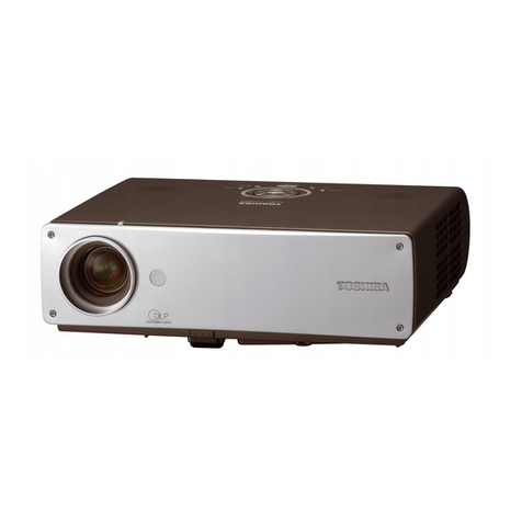
  9. Toshiba TLP-561 User manual

Toshiba TLP-561 User manual

SERVICE MANUAL
FILE NO. 333-200206
SUPPLEMENT
3LCD PROJECTOR
TLP-560/561
TLP-260/261
This service manual covers only different portions from service manual (File No. 330-200103)
for TLP55/25 series.
—SUMMARY —
Document Created in Japan May.,2002
1/2
As for TLP56/26, a RGB Out terminal is addition to TLP55/25.
TLP55/25 signal input terminal TLP56/26 signal input terminal (RGB Out addition)
The following parts list covers only the different parts from the base models,
For the other parts, please refer to the service manual(File No, 330-200103) of the base models,
The base models of each model are shown below,
Model Base Model
TLP560 TLP550
TLP561 TLP551 (with document imaging camera)
TLP260 TLP250
TLP261 TLP251 (with document imaging camera)
Difference parts list (TLP56 Series)
Location
No. Part No.
(US) Part No.
(EU) Part No.
(UK)
Description
E200 23405130 23405130 23405130 Optical Engine
E260S 23405132 23405132 23405132 Optical Main Frame
E261S 23405071 23405071 23405071 Optical Sub Frame
U001 23787665 23787665 23787665 PC Board MAIN
U002 23787666 23787666 23787666 PC Board SENSOR
U003 23787667 23787667 23787667 PC Board DOOR
A100 23530337 23530337 23530337 Top Cover
A300 23553722 23553722 23553722 Front Tag TLP560
A303 23553859 23553859 23553859 Label Rating TLP560
A320 23553726 23553726 23553726 Label Carton Box TLP560
A300 23553721 23553721 23553721 Front Tag TLP561
A303 23553858 23553858 23553858 Label Rating TLP561
A320 23553725 23553725 23553725 Label Carton Box TLP561
Y200 23565648 23565648 23565648 Owner’s Manual CD-ROM
Y201 23565649 --------- ---------
Owner’s Manual E/F
Y202 23565650 --------- ---------
Owner’s Manual SPA
Y204 --------- 23565651 --------- Owner’s Manual E/G
Y205 --------- 23565652 --------- Owner’s Manual F/S
Y206 --------- ---------
23565653 Owner’s Manual ENG
Y221 23589364 23589364 23589364 Sheet Quick ENG
Y222 23589365 23589365 --------- Sheet Quick FRA
Y223 23589366 23589366 --------- Sheet Quick SPA
Y225 --------- 23589368 --------- Sheet Quick GER
Y226 --------- 23589369 --------- Sheet Quick POR
Y227 --------- 23589370 --------- Sheet Quick ITA
2/2
Difference parts list (TLP26 Series)
Location
No. Part No.
(US) Part No.
(EU) Part No.
(UK)
Description
E200 23405140 23405140 23405140 Optical Engine
E260S 23405111 23405111 23405111 Optical Main Frame
E261S 23405071 23405071 23405071 Optical Sub Frame
U001 23787668 23787668 23787668 PC Board MAIN
U002 23787669 23787669 23787669 PC Board SENSOR
U003 23787670 23787670 23787670 PC Board DOOR
A100 23530337 23530337 23530337 Top Cover
A300 23553863 23553863 23553863 Front Tag TLP260
A303 23553861 23553861 23553861 Label Rating TLP260
A320 23553865 23553865 23553865 Label Carton Box TLP260
A300 23553862 23553862 23553862 Front Tag TLP261
A303 23553860 23553860 23553860 Label Rating TLP261
A320 23553864 23553864 23553864 Label Carton Box TLP261
Y200 23565648 23565648 23565648 Owner’s Manual CD-ROM
Y201 23565649 --------- ---------
Owner’s Manual E/F
Y202 23565650 --------- ---------
Owner’s Manual SPA
Y204 --------- 23565651 --------- Owner’s Manual E/G
Y205 --------- 23565652 --------- Owner’s Manual F/S
Y206 --------- ---------
23565653 Owner’s Manual ENG
Y221 23589364 23589364 23589364 Sheet Quick ENG
Y222 23589365 23589365 --------- Sheet Quick FRA
Y223 23589366 23589366 --------- Sheet Quick SPA
Y225 --------- 23589368 --------- Sheet Quick GER
Y226 --------- 23589369 --------- Sheet Quick POR
Y227 --------- 23589370 --------- Sheet Quick ITA
TOS
H
IBA CORPORATION
1--1, SHIBAURA 1-- CHOME, MINATO -- KU, TOKYO 105 -- 8001, JAPAN
SERVICE MANUAL
FILE NO. 330-200103
SUPPLEMENT
3LCD DATA PROJECTOR
TLP-250/251/250C/251C
TLP-550/551/550C/551C
SECTION 1
PART REPLACEMENT AND
ADJUSTMENT PROCEDURES
1. LOCATION OF MAIN PARTS
L
C
D BL
OC
K
Z1
00
: INTAKE FA
N
P
800
: P
O
WER
SU
PPL
Y
E2
00
:
O
PTI
C
AL EN
G
IN
E
E2
0
1A: PR
OJ
E
C
TI
O
N LE
N
LAMP H
OUS
IN
G
S
PEAKER B
L
Z1
0
1: EXHA
US
T FA
N
:
BALLA
S
T P
O
WER
SU
PPL
Y
2. LOCATION OF PC BOARD
U00
1: MAIN P
C
B
O
AR
D
U002: SENSOR PC BOARD
U002:
1-1
U003: SWITCH PC BOARD
3. REPLACEMENT OF MECHANICAL PARTS
3-1. Lamp Assembly
1-2
CAUTIONS BEFORE SERVICING
Electronic parts are susceptible to static electricity and may easily be damaged, so do not forget to take
proper grounding treatment as required.
Many screws are used inside the unit. To prevent missing, dropping, etc. of the screws, always use a
magnetized screwdriver in servicing. Several kinds of screws are used and some of them need special
cautions. That is, take care of the tapping screws securing molded parts and fine pitch screws used to
secure metal parts. If they are used improperly, the screw holes will be easily damaged and the parts can
not be fixed.
Step Figure Explanation
1
2
3
4
Loosen 2 screws (M3 x 8).
These screws are retained with split washers.
Remove the lamp cover.
Loosen 2 screws that secure the lamp module (M3 x 8).
These screws are retained with split washers.
Lift the lamp module and slide out from the projector.
3-2.Top Cover
1-3
Step Figure Explanation
1
2
3
4
5
[Left Side]
Remove 3 screws (M3 x 6).
[Right Side]
Remove 6 screws (M3 x 6).
[Front]
Remove front cover.
Screw : type [M-1]
Screw : type [M-1]
Remove 1 screw (M3 x 6).
Screw : type [M-1]
Slide front cover to the right.
3-2.Top Cover (Continued)
1-4
Step Figure Explanation
6
7
[Rear]
Remove 1 screws (M2 x 6). Screw : type [M-1]
Top cover can be removed by lifting left edge.
3-3. Main PC Board
1-5
Step Figure Explanation
1
2
3
Remove all cables and connectors.
Remove 5 screws (M3 x 6).
Remove 1 screws (M3 x 6).
[Note]
The screw here is also fixing the grand wire.
Screw : type [M-1]
Screw : type [M-1]
Remove lens shift dial.
4
3-3. Main PC Board (Continued)
1-6
Step Figure Explanation
5
6
Remove metal plate.
Remove 2 screws (M3 x 6).
Screw : type [M-1]
Remove 2 screws (M3 x 8). Screw : t
y
pe [M-10
]
3-4. Optical Engine
1-7
Step Figure Explanation
1
2
3
4
5
Remove 1 screw (M3 x 6).......A
Remove Thermal switch.
Remove metal plate.
Screw : type [M-1]
Remove 2 screws (3 x 8) Screw : type [M-2]
Remove 2 screws (3 x 8)......B Screw : type [M-2]
AB
B
3-4. Optical Engine (Continued)
1-8
Step Figure Explanation
6
7
7a
7b
Remove lamp housing.
Remove 3 screws (M3 x 15).
Screw : type [M-4]
a
b
3-4. Optical Engine (Continued)
1-9
Step Figure Explanation
8
9
Remove 3 screws (M3 x 8) .
Separate the main frame and sub frame from the engine
block.
Screw : type [M-2]
Sub frame
Sub fram
Main frame
3-5. MULTI-PBS (Polarizing Beam Splitter)
1-10
Step Figure Explanation
1
2
3
4
Remove 3 screws (M3 x 15) ....A
Press the Multi-PBS up from cooling space.
Remove the Multi-PBS.
Screw : type [M-8]
Remove 1 screws (M2.5 x 15) ....B Screw : t
y
pe [M-9
]
A
B
Prism Lamp
Lamp
Lamp
[Note]
Make sure the direction of the PBS when you install.
Lamp SIDE
Prism SIDE
PBS
Rotation Film
Multi Lens
TOP VIEW
3-6. Polarized Plate
1-11
Step Figure Explanation
1
2
3
4
Remve the one screw.
Remove the stopper.
Remove the holder and polarized plate.
[Note]
The film side must be faced to the LCD panel when installing
and the color must be related with the color of LCD panel.
Color
Marking
Panel Sidepolarizer film
polarizer film
polarizer film
5
Tighten a screw in the position where 100% black image
screen gets the darkest.
3-7. Intake Fan
1-12
Step Figure Explanation
1
2
3
4
5
Remove 2 screw (3 x 8).
Remove intake fan block from the bottom cabinet.( It pulls
up along with a rail. )
Remove filter block from the bottom cabinet.
The filter is split like this.
Screw : type [M-2]
Remove 2 screws (3 x 8).
Screw : type [M-2]
Rail
3-7. Intake Fan (Continued)
1-13
Step Figure Explanation
6
7
Remove 2 screw (3 x 47).
The Intake fan block is split like this.
Screw : type [M-5]
3-8. Exaust Fan
1-14
Step Figure Explanation
1
2
3
4
Remove 1 screw (3 x 8).
Remove intake fan block from the bottom cabinet.( It pulls
up along with a rail. )
The exaust fan block is split like this.
Screw : type [M-2]
Remove 2 screws (3 x 15).
Screw : type [M-6]
Rail
1-15
3-9. Speaker Block
Step Figure Explanation
1
2
Remove 2 screws (3 x 8).
Remove 1 screw (3 x 8).
The speaker will be removed like this.
Screw : type [M-2]
Screw : type [M-2]

This manual suits for next models

10

Other Toshiba Projector manuals

Toshiba TLP-MT7 - LCD Projector - 1000 ANSI Lumens User manual

Toshiba

Toshiba TLP-MT7 - LCD Projector - 1000 ANSI Lumens User manual

Toshiba TDP-TW100U User manual

Toshiba

Toshiba TDP-TW100U User manual

Toshiba TDP-D1-US User manual

Toshiba

Toshiba TDP-D1-US User manual

Toshiba TDP-TW300U User manual

Toshiba

Toshiba TDP-TW300U User manual

Toshiba TDP-T100U User manual

Toshiba

Toshiba TDP-T100U User manual

Toshiba TDP-T250U User manual

Toshiba

Toshiba TDP-T250U User manual

Toshiba TLP-S200 User manual

Toshiba

Toshiba TLP-S200 User manual

Toshiba TDP-SC35U User manual

Toshiba

Toshiba TDP-SC35U User manual

Toshiba X100U - TLP XGA LCD Projector User manual

Toshiba

Toshiba X100U - TLP XGA LCD Projector User manual

Toshiba TLP-710U User manual

Toshiba

Toshiba TLP-710U User manual

Toshiba TLP680U - SXGA LCD Projector User manual

Toshiba

Toshiba TLP680U - SXGA LCD Projector User manual

Toshiba C1770 Use and maintenance manual

Toshiba

Toshiba C1770 Use and maintenance manual

Toshiba TLP-T50M User manual

Toshiba

Toshiba TLP-T50M User manual

Toshiba TDP-TW355U User manual

Toshiba

Toshiba TDP-TW355U User manual

Toshiba TLP-XD2000 - XGA LCD Projector User manual

Toshiba

Toshiba TLP-XD2000 - XGA LCD Projector User manual

Toshiba TDP-T98U User manual

Toshiba

Toshiba TDP-T98U User manual

Toshiba TLP-T50M User manual

Toshiba

Toshiba TLP-T50M User manual

Toshiba TLP-XD2000U User manual

Toshiba

Toshiba TLP-XD2000U User manual

Toshiba TLP-X10E User manual

Toshiba

Toshiba TLP-X10E User manual

Toshiba t100 User manual

Toshiba

Toshiba t100 User manual

Toshiba TDP-TW355J User manual

Toshiba

Toshiba TDP-TW355J User manual

Toshiba TLP-X2500C User manual

Toshiba

Toshiba TLP-X2500C User manual

Toshiba Projector-Laptop User manual

Toshiba

Toshiba Projector-Laptop User manual

Toshiba TDP-MT8 User manual

Toshiba

Toshiba TDP-MT8 User manual

Popular Projector manuals by other brands

Delta Electronics DP-2618 Specifications

Delta Electronics

Delta Electronics DP-2618 Specifications

Hitachi CP-X615 series user manual

Hitachi

Hitachi CP-X615 series user manual

Panasonic PT-LB50EA Specification sheet

Panasonic

Panasonic PT-LB50EA Specification sheet

Optoma H55 datasheet

Optoma

Optoma H55 datasheet

Barco R9002411 owner's manual

Barco

Barco R9002411 owner's manual

Epson EB-PU2113W user guide

Epson

Epson EB-PU2113W user guide

Marco CP-690E instruction manual

Marco

Marco CP-690E instruction manual

Eiki EIP-3000N Setup manual

Eiki

Eiki EIP-3000N Setup manual

Sony VPL-PX11 Brochure & specs

Sony

Sony VPL-PX11 Brochure & specs

Optoma GT200 user manual

Optoma

Optoma GT200 user manual

Optoma GT760 datasheet

Optoma

Optoma GT760 datasheet

3M Digital Projector X75 Operator's guide

3M

3M Digital Projector X75 Operator's guide

ViewSonic PJ513D Specifications

ViewSonic

ViewSonic PJ513D Specifications

Mathmos Sensory Lights Space Projector instructions

Mathmos

Mathmos Sensory Lights Space Projector instructions

ViewSonic PJ1173 - XGA LCD Projector user guide

ViewSonic

ViewSonic PJ1173 - XGA LCD Projector user guide

Sanyo PLC-SU32 Comparison chart

Sanyo

Sanyo PLC-SU32 Comparison chart

LG BN315 Service manual

LG

LG BN315 Service manual

Sony VPL-FH36 Operating	 instruction

Sony

Sony VPL-FH36 Operating instruction

manuals.online logo
manuals.online logoBrands
  • About & Mission
  • Contact us
  • Privacy Policy
  • Terms and Conditions

Copyright 2025 Manuals.Online. All Rights Reserved.