manuals.online logo
Brands
  1. Home
  2. •
  3. Brands
  4. •
  5. Toshiba
  6. •
  7. Telephone System
  8. •
  9. Toshiba Strata S Manual

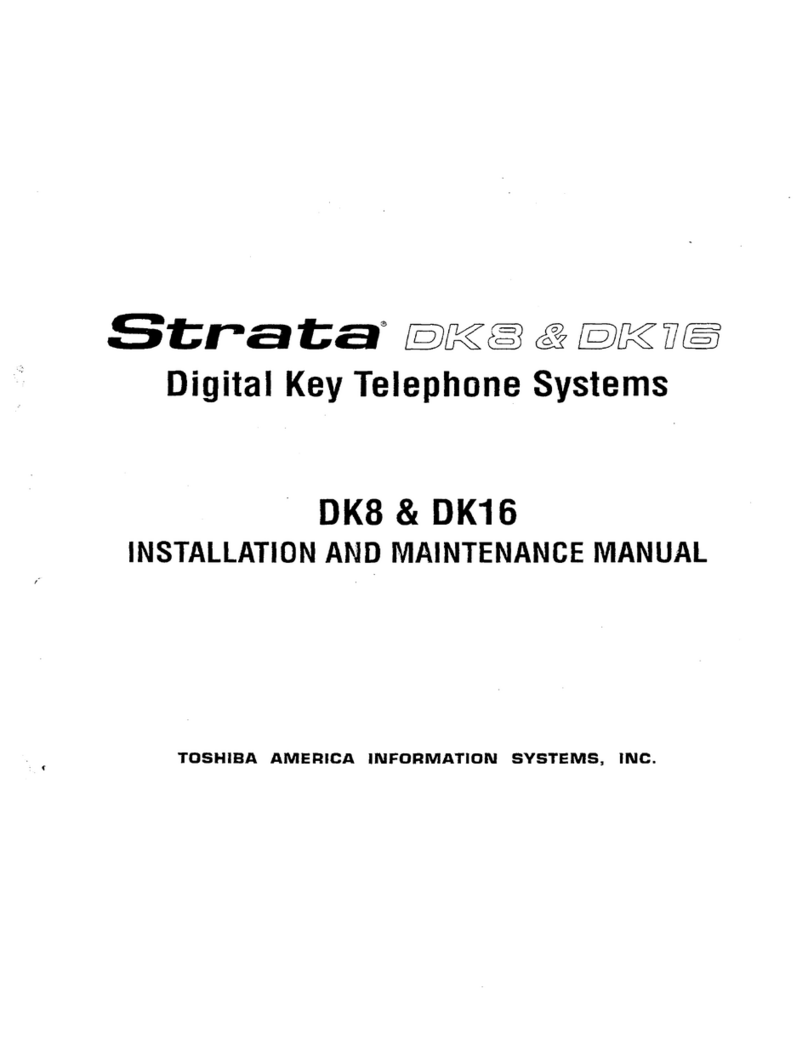
Toshiba Strata S Manual

Strats
S
ELECTRONIC KEY TELEPHONE SYSTEM
INSTALLATION AND MAINTENANCE MANUAL
-
TOSHIBA SYSTEM PRACTICES
ELECTRONIC KEY TELEPHONE SYSTEM TOSHIBA PUBLICATIONS
SECTION 100-003-000 .
JULY
1984
e..
Strata” S
(AKA: HARRIS LANIER SERIES III)
ELECTRONIC KEY TELEPHONE SYSTEM
INSTALLATION AND MAINTENANCE MANUAL
.
TABLE OF CONTENTS
FCC REGULATIONS
SECTION 100-003-000
GENERAL DESCRIPTION
SECTION 100-003-l 00
INSTALLATION INSTRUCTIONS SECTION 100-003-200
POWER SUPPLY INSTALLATION INSTRUCTIONS
SECTION 100-003-250
PROGRAMMING PROCEDURES SECTION 100-003-300
OPERATING PROCEDURES SECTION 100-003-400
FAULT FINDING PROCEDURES
SECTION 100-003-500
TOSHIBA SYSTEM PRACTICES
ELECTRONIC KEY TELEPHONE SYSTEM GENERAL DESCRIPTION
SECTION 100-003-l 00
Strata
S@
GENERAL DESCRIPTION
,.--
P
TOSHIBA SYSTEM PRACTICES
ELECTRONIC KEY TELEPHONE SYSTEM
_..
Strata S
GENERAL DESCRIPTION
TABLE
of CONTENTS
GENERAL
OESCRlPTlON
SECTION 100-003-l 00
JULY 1994
PARAGRAPH SUBJECT PAGE
01
02
02.00
02.10
03
04
05
06
06.00
06.10
06.20
06.30
06.40
07
07.00
07.10
07.20
TABLE of CONTENTS
............................
i
ILLUSTRATION LIST
............................
i
GENERAL
1
PHYSICALDESCRIPTI’ONS’:::::::::::::::::::::::::
1
Key Service Unit
............................
1
Electronic Key Telephone
TABLE A-SUMMARY OF
ELEC;R;C~;CHARACTERlST;CS
-
: : : : : : : : : :2
4 .
ELECTRICAL CHARACTERISTICS
......................
5
FEATURES and SERVICES
5
TABLEB-STANDARDFEATURES’:::::::::::::::::::::: 5
TABLE C-OPTIONAL FEATURES ...................... 5
SYSTEM OPERATION
SYSTEM CONFIGURATION
’
: : : : : : : : : : : : : : : : : : : : : : : : :6
8
Key Service Unit
............................ 8
Power Supply Assembly
........................
8
Station Equipment
...........................
9
Installation
................................
10
...
Maintenance
...................... 10
FEATURESandOPERATlON
................
::::::::
10
General
................................ 10
Standard Features
................... 10
OptionalFeatures
...................
::::::::
12
NUMBER TITLE PAGE
1
2
3
4
5
6
7
8
3
10
11
12
13
14
15
MKSU (Dimensions)
..........................
1
MKSU Cabinet
.............................
1
MKSU (Internal)
............................
1
1 O-key “S” Electronic Key Telephone (EKT)
................ 2
1 O-key Speakerphone EKT
.......................
3
Busy Lamp Field (BLF) EKT
....................... 3
20-key
Executive EKT
SystemDiagram
...................................... 3
::::::::
6
Functional Block Diagram
........................ 7
MKSU (Internal)
............................ 8
1 O-key
“S”
EKT ............................ 3
Key Layout
............................... 3
lo-key
EKT
...............................
9
BLF EKT
PO-keyEKT”::.
.....................................
10
:::::::::
10
. .
-
P
w..
Ot GENERAL-
01 .OO Summary Description
01.01
Strata
S is an electronic key tele-
phone system with many standard features utiliz-
ing stored program control, custom LSI circuitry,
solid-state space division switching, and reduced
station cabling. Served by a key service unit
(MKSU) housed in a single cabinet, the system has
a capacity of three central office/PBX lines, one
intercom line, and eight station lines.
01.02 Strata S utilizes specially designed
electronic key telephones (EKTs). Each EKT is con-
nected to the system via industry-standard 2-pair
cabling, and is equipped with a push-button dial
pad. Solid-state electronics within the MKSU
translate signals from the station dial pad into
either DTMF or rotary dial signals, as required by
the central off ice.
01.03 Strata S is electrically compatible
with the public telephone network and is also
designed to function in a “behind PBX” envi-
ronment.
01.04 Maintenance procedures are based on
quickly locating and replacing defective sub-assem-
blies, keeping service disruption to a minimum.
02 PHYSICAL DESCRIPTIONS
02.00 Key Service Unit
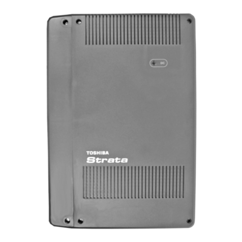
02.01 Designed for wall mounting, the
Strata S MKSU is housed in a single plastic
cabinet (Figure 1) with the following dimensions:
GENERAL
DESCRIPTION
SECTION 100-003-100
JULY 1984
Height: 16.5 inches (420 mm)
Width: 12.0 inches (306 mm)
Depth: 2.6 inches (67 mm)
Weight: 6.2 Ibs.
(2.8
kg) .
02.02 The cabinet consists of a base, cover. and
side covers (Figure 2)
I FIGURE 2-MKSU CABINET
02.03 The MKSU is factory-equipped with two
PCBs (MMAU and ACOU). The dimensions of
these PCBs are:
MMAU: 15.4 x 9.5 inches (390 x 241 mm)
ACOU: 9.4 x 6.3 inches (239 x 160 mm)
02.04 The MMAU PCB is secured to the cabinet
base (Figure 3). The ACOU is attached to the
MMAU with four screws. and is connected to it via
four 1O-pin connectors.
FIGURE 1-MKSU (Dimensions)
-l-
FIGURE 3-MKSU (Internal)
GENERAL DESCRIPTION ‘.
SEGTION 106-003-100
JULY 1984
L
Speaker -I I
CQ
cl3
Yo
/
o O.+,,Messege Waiting/
YIR Flash Key
“52 I DND
Kay
,.
OSb
OS I
Programmable
“- Kers
Speaker Volume
Modluler
Cord
(Dial Tone)
1 O-key
l
*S’* TVPE EKT
FIGURE 4-l O-key “S” EKT
02.05 Optional PCBs (AEPU, AMOU and APFU) .equipped with four permanently dedicated keys
are field installed. The AEPU is secured to the and either 10 or 20 feature keys. Because of the
MMAU with two screws and is connected to it via number of these feature keys, these EKTs are
two 1O-pin connectors. The AMOU and APFU at- known as a lo-key EKT (Figure 5). a lo-key Busy
tach to the right side panel and connect via small Lamp Field (BLF) EKT (Figure 6) and a 20-key EKT
connector-ended wire harnesses. (Figure 7).
02.06 All external devices are connected to the
MKSU connector panels with industry-standard
connectors.
02.12 The 1O-key “S” EKT measures:
02.10 Electronic Key Telephones Height: 3.5 inches (88.9 mm)
Width: 6.0 inches (152 mm)
Depth: 9.0 inches (229 mm)
02.11 Four diierent Electronic Key Telephones
(EKTs) may be used in the
Strata
system. The
standard EKT (Figure 4), known as a lo-key “S”
EKT, is equipped with three permanently dedi-
cated keys and ten line/feature keys. All three
optional EKTs are full speakerphones and are
and is equipped with 13 line and feature keys in
addition to its push-button dial pad. Three of the
keys are utilized for central office/PBX lines, one
for intercom access, and the remaining keys for
feature operation.
-2-
‘.
GENERAL DESCRlPTlDN
SECTION 100-003-l 00
JULY 1984
Handset -
Speaker -
/
Modular
Cord
Speaker Volume -
Rina Tone 81 Intercom
Speaker On/Off LED.
/
!+eaker On/Off Key
Dial,Pad
Voice Level Feature & !Speaker Volume -
Function LEDs Dial Tone & Voice
/Level
Message Waiting
,& Flash Key
/
Do Not Disturb
I /KW
.--
I
Programmable
Keys
.--
.--
1
CO Keys
-I .
.-- Intercom
- Key
’rk
LED
\
Hold Key
Conference Key
\
Microphone
FIGURE 5-lo-key SPEAKERPHONE EKT
I
:
.?yJii~$’ - ;rF. ; ‘,
FIG&E 6-BLF EKT
4’
-3-
GENERAL DESCRIPTION
SECTION 100-003-100
JULY 1994
-.. . -
02.13 All three optional EKTs have the same
external dimensions: answerback and full speakerphone capability.
Height: 4.0 inches (102 mm)
Width: 8.8 inches (224 mm)
Depth: 9.1 inches (230 mm)
02.16 The optional 1O-key BLF EKT provides the
same features as those listed in Paragraph 02.15,
plus an LED indication of which stations are in
use.
Each is equipped with either 14 or 24 line/feature
keys in addition to a push-button dial pad. Again,
three of the keysare utilized for CO/PBX lines, one
for intercom access, and the remaining keys are
used for feature operation.
02.14 System software assignments permit some
variation to the feature keys on all four EKTs.
02.17 The optional 20-key EKT provides the
same features as those listed in Paragraph 02.15,
and has ten additional feature keys. That is, three
CO/PBX keys, one intercom key, and 16 feature
keys that may be used as automatic dialing keys,
direct station selection (DSS) keys, etc. Three dif-
ferent combinations of feature keys may be
selected via programming.
02.15. The optional 1O-key EKT provides the 02.18 All EKTs feature modular handset cords
same programmable feature keys as the standard and are connected to the system via four-con-
EKT, plus a microphone control key, handsfree ductor modular line cords.
TABLE A
SUMMARY OF ELECTRICAL CHARACTERISTICS
Station Loop Limits
Ringing Tone
CO tine (idle)
(busy)
Intercom Line
Busy Override Tone
Dial Tone (Intercom)
Ring-back Tone
Busy Tone
Do Not Disturb Tone
Voice Page Warning Tone
Executive Override Warning Tone
Dialing .
Primary Power
Hold Recall Tone
Environmental Specifications
Operating Temperature
Operating Humidity
1,DOD ft. (305 M), 24 AWG 4
600/800 Hz, modulated by 16 Hz, 1 second
on--3secondsoff
2400 Hz, modulated by 10 Hz, 1 second on-
3 seconds off
606 Hz, 1 second on-3 seconds off
2400 Hz, 1 second on-3 seconds off
600 Hz, continuous
600 Hz, 1 second on-3 seconds off
600 Hz, 0.25 second on-O.25 second off
600 Hz, 0.12 second on-O. 12 second off
600 Hz, 1 second on only (via EKT speaker)
600 Hz, 0.5 second on only (via handset)
Push-button; system-generated DTMF or dial
pulse
117VAC,6OHz,4OVA
2400 Hz, modulated by 10 Hz, 1 second on-
1 second off ..=
32 - 122OF (0 - 50%)
20 - 6096 relative humidity (without
condensation)
GENERAL DESCRIPTION
SECTION 100-003-l 00
JULY 1994
-.’ 03 ELECTRIC/ii CHARACTERISTICS
03.01 The electrical characteristics of the sys-
tern are detailed in Table A.
03.02 The MKSU operates from an external 24
VDC power supply.
03.03 Loss of AC power will cause operational
failure of the system. System memory, however, is
protected from loss due to power failure with a
memory back-up battery. Full system reserve
power is available as an option.
04 FEATURES and SERVICES
04.01 The features and services of the
Strata S electronic key telephone system are
summarized in Tables B and C, which list the
standard and optional features, respectively.
TABLE B
STANDARD FEATURES
SYSTEM
l
All Call Voice Page
l
Alternate Point Answer
l
Automatic Dialing-System
l
Automatic Hold Recall
l
Automatic Privacy -
l
Automatic Release from Hold
l
Busy Override
l
Conference-Multi-station (non-amplified)

l
Conference-Multi-trunk (non-amplified)
l
Distinctive Ringing
l
DTMF and Dial Pulse Compatible
l
External Page Interface
l
Flash Key (PBX Transfer or CO Dial Tone
Recall)
l
Flexible Line Ringing Assignment
l
Live System Programming
l
Message Waiting
l
Music-on-hold Interface
l
Night Transfer
l
Non-blocking Dialing
l
Outgoing Call Restriction
l
PBX Compatible
l
Private CO Lines
l
Repeat Last Number Dialed
l
Toll Restriction
l
Voice or Tone Signalling
l
Wall Mountable MKSU
STATION
l
Automatic Dialing-Station
l
Automatic One-touch Dialing (Programmable)
l
Do Not Disturb
l
Do Not Disturb Override
l
Executive Override of Privacy
l
l-called Illumination
l
i-hold Illumination
l
l-use Illumination
l
Modular Handset and Line Cords
l
On-hook Dialing
l
Push-button Dialing
l
Ringing Line Preference
TABLE C
OPTIONAL FEATURES
0 1O-key EKT with
Speakerphone
l
Microphone
Control Key
l
Busy Lamp Field
(BLF) EKT
l
Music-on-hold
Source
l
20-key
Executive EKT
l
Speakerphone
l
External Page Amplifier
l
System Battery Baaup
l
Handsfree Answerback
l
Wall
Mounting Kits for all EKTs
-5
GENERAL DESCRIPTION
SECTION 100-003-l 00
AJLY 1984
M.. 05 SYSTEii OPERATIO’N
05.01 The system (Figure 8) consists of an
MKSU, power supply and up to eight EKTs. All
connections between the MKSU and the EKTs are
made via a customer-provided main distribution
frame (MDF). Using modular line cords, the CO
lines are then connected between the ACOU and
locally-supplied RJ-25C jacks. An external tuner
or an AMOU PCB is required if the music-on-hold
feature is to be utilized.
Side
Panel
5 VAC b
MKSUMKSU
f External 1
n +
2-pair
FIGURE 8-SYSTEM DIAGRAM
-6-
E
-05.02 A functio.nal block diagram of the
Strata S MKSU is shown in Figure 9; it con-
sists of the main PCB (MMAU), which includes a
station interface and central control equipment,
and a CO interface (ACOU). The optional Paging
Amplifier module (AEPU), internal music-on-hold
.source (AMOU), and Power Failure module(APFU)
are also shown.
05.03 Connections between the station voice
GENERAL DESCRIPTION
‘. SECTION 100-003-l 00
JULY 1994
lines and the CO lines are via theswitching matrix
provided on the MMAU. A similar matrix is pro-
vided on the MMAU for intercom connection, pag-
ing connections and for the distribution of the
various system tones (Dial, Busy, etc.). .
05.04 The system is under the control of a
single-chip microprocessor, which is located, along
with the system programs and data memories, on
the MMAU PCB.
MM-AU
I---- -ncou - --z-I
-
I
To
CO/PBX
1 (3 lines)
-
DATA
..-
115VAC
b
FIGURE 9-FUNCTIONAL BLOCK DIAGRAM
-7-
GENERAL DESCRIPTION
SECTION 100-003-l 00
JULY 1984
e.. 06 SYSTEM CONFIGURATION
06.00 Key Service Unit
06.01 Completewith all options, the MKSU util-
izes five circuit boards. The names and functions
of the PCBs are:
ACOU (MF or DP):
An interface between the MKSU and the pub-
lic telephone network or PBX lines. Ring detec-
tion, hold and dial outpulsing for three circuits
are performed by this PCB. Depending upon
local CO requirements, an MF or DP type of
ACOU will be provided (MF for DTMF outpuls-
ing; DP for rotary dial outpulsing).
MMAU:
The main PCB of the MSKU, consists of the
following four functions:
a) Station Interface-An interface between
the MKSU and EKTs, which includes the
solid-state space division matrix used for
voice connections between the EKTs .and
the CO/PBX lines. Two-pair wiring is
required for each EKT; one pair carrying
voice and the other pair carrying data to
and from the EKT.
b) Control-All system control functions are
performed by the single-chip micro-pro-
cessor. The system program stored in
ROM, the RAM for system operations, and
the RAM for system data storage are also
located on this circuit board.
c) Tone-Performs a number of miscel-
laneous system functions:
l
Generates system tones.
0 Provides the switching matrix for the
delivery of tones for both paging and
intercom connections.
l
Houses the interface for the external
paw.
l
Houses the interface for music-on-hold.
d) Power Regulating-Performs the following:
l
Provides connection points for the 24
VDC input power.
l
Houses the voltage regulators that pro-
vide 12 and 5 VDC for system operation.
l
Houses a circuit breaker that protects
the 24 VDC, EKT, and MKSU circuits.
AEPU:
An optional 3-watt amplifier for external paging.
AMOU:
An optional music-on-hold source.
APFU:
An optional power failure transfer module
used to transfer the CO lines to single line
telephones in the event of a power failure.
06.02 The MKSU arrangement illustrated in
Figure 10 shows the locations of the various PCBs.
The MMAU, which hosts the ACOU, is secured to
the MSKU with six screws. The ACOU, attached to
the MMAU with four screws, is connected to it via
four 1O-pin connectors.
FIGURE lo-MKSU (Interior)
06.03 The optional AEPU is attached to the
MMAU with two screws, and connected with the
MMAU via two lo-pin connectors.
06.04 The optional music-on-hold source
(AMOU) is secured to the MKSU right side panel,
and connected with the MMAU via a 3-pin
connector.
06.05 The optional power failure transfer unit
(APFU) is secured to the MKSU right side panel
and connected with the ACOU via four 2-pin
connectors.
06.10 Power Supply Assembly
06.11 The system requires 24 VDC. Two power
supplies are available; MPSA-200 and MPSA-
512. Each of these requires 117 VAC, 60 Hz. The
permissible AC input voltage range is 90 - 130
VAC.
-..06.12 An optional battery back-up unit (PBBU)
is available for the MPSA-200. With the optional
battery back-up assembly installed, all functions of
the Strata S system. will continue to operate
for several hours (the actual time period is in direct
ratio to the type and size of batteries selected) after
a loss of normal electrical power. No calls will be
disconnected during switch-over to battery power.
FIGURE 1 l-l O-key “S” EKT
06.20 Station Equipment
06.21
The principal components of the lo-key
“S” electronic key telephone (Figure 11) are:
handset, dial pad, speaker, sliding ringing/speaker
volume control, 3-position volume control, one
intercom key, three CO/PBX line keys and nine
feature keys. LED indicators are provided for all
_- -.
keys except FOLD] and [m%] keys. With the
exception of the three permanently dedicated
keys, the feature keys can be assigned to one of
two modes by programming (see Figure 12).
06.22 Standard features of the 1O-key “S” EKT
include, among other standard features, paging,
one-touch automatic dialing keys,
and auto-redial.
In initialized mode, three of the keys are utilized for
CO/PBX lines, one for intercom
access, four keys
for
one-touch automatic dialing and one each for
Do Not Disturb and Message Waiting/Flash.
GENERAL DESCRIPTION
SECTlON 100-003-l 00
JULY 1994
1O-key 1 O-key 20-key 20-key 20-key
#l #2 #I #2 #3
FIGURE 12-KEY LAYOUT
06.23 The optional lo-key EKT (Figure 13) pro-
vides the same programmable feature keys as the
standard EKT. plus a microphone control keym,
handsfree answerback and full speakerphone
capability.
I I
FIGURE 13-l O-key EKT
-S-
GENEML DESCRlPTlDN
SECTION 100-003-l 00
aJ~lY 1994 __
06.24 The optional lo-key BLF EKT (Figure 14)
provides the same features as those listed in Para-
graph 06.23, plus an LED indication on which
stations are in use.
I -: ..
06.26 All EKTs feature modular handset cords
and are connected to the system via 4-conductor
modular line cords. ..
06.27 All EKTs are easily converted for wall
mounting with an optional kit.
06.30 Installation
06.31 External devices are connected to the
MKSU via connectors and terminals on the side
panels.
FIGURE 14--BLF EKT
06.25 The optional 20-key EKT (Figure 15) pro-
vides the same features as those listed in Para-
graph 06.23, and has ten additional feature keys.
That is, three CO/PBX keys, one intercom key, and
16 feature keys that may be used as automatic
dialing keys, direct station selection (DSS) keys,
etc. Three different combinations of feature keys
may be selected via programming, as shown in
Fiaure 12.
07 FEATURES and OPERATION
FIGURE 15-20-key EKT
a)
b)
cl
CO/PBX lines are connected to the MKSU
right side panel via a 3-pair modular cord.
The station connection points are extended
from the MKSU to the MDF using one cable
equipped with a standard 50-pin amphenol-
type connector. The individual EKTs are con-
nected to the MDF with 2-pair station cable.
Screw-terminal barrier strips are mounted on
the side of the MKSU to provide attachment
points for the following connections:
24 VDC power input (left side)
Music-on-hold source input (right side) -.
External page output (right side) ?4
06.32 The power supply is mounted to the well’
separately from the MKSU and connected to the
24 VDC input on the MKSU left side.
06.40 Maintenance
06.41 Faults in Strata S are repaired by
replacing any faulty component (EKT, printed cir-
cuit board, sub-assembly, etc.) and returning it to
the manufacturer for repair.
07.00
General
07.01 This section contains brief descriptions of
the
Strata
Sfeatures listed earlier in Tables B
and C and some associated operating instructions.
Detailed operating instructions can be found in
either the Strata S USER GUIDE or Operat-
ing Procedures. Section 100-003-4C0,
Strata
S Jnstallation and Maintenance Manual.
07.10 Standard Features
07.11 System
All Call Voice Page:
Dialing a 1-digit access code permits a station
user to page via all EKT speakers and (option-
ally)the External Page speaker simultaneously.
-1 o-
--.Alternate Point Answer:
CO/PBX or intercom calls can be answered
from any station.
Automatic Dialing-System:
This standard feature allows 40 numbers to be
stored in the system memory. After selecting
an outgoing line, any station user can cause
one of the stored numbers to be outpulsed by
dialing the proper address code.
Automatic Hold Recall:
A CO line placed on hold by any station will
recall that station after a programmable period
of time.
Automatic Privacy:
Privacy is automatic on all connections.
Automatic Release from Hold:
The system automatically releases held CO
lines if a disconnect signal is received from the
central off ice.
Busy Override:
After dialing a busy station and receiving a
busy tone, the caller can dial a
q
and cause a
tone burst to be sounded via the called EKT
speaker.
Conference-Multi-station (non-amplified):
Conferencing is permitted to a maximum of
four stations and one CO or the intercom line.
Conference-Multi-trunk (non-amplified):
Conferencing of two CO lines and three sta-
tions is permitted.
Distinctive Ringing:
CO line and intercom calls are distinguished
by different ringing tones.
DTMF and Dial Pulse Compatible:
DTMF or dial pulse signalling can be sent to
the CO/PBX line by installing the proper
ACOU PCB type.
External Page Interface:
A 6OD-ohm connection point is provided for a
customer-provided external speaker. An am-
plifier is also required, which can be mounted
externally, or the AEPU (see Paragraph 07.20,
External Page Amplifier) can be mounted in
the MKSU. If the AEPU is used, the output
impedance is 8 ohms. This page circuit is
accessed as part of the All Call Voice Page
- feature.
GENERAL DESCRIPTION
SECTION 100-003-100
JULY 1984
Flash Key (PSX Transfer or CO Dial Tone Recall):
All EKTs are equipped with a Message Wait-
ing/Flash m) key which, when operated
while connected to a CO/PBX line, causes a
timed “flash” to be transmitted to the CO or
PBX. The timing of the flash can be pro-
grammed to signal a PBX for feature operation
or can be long enough to cause a disconnect
and dial tone recall on a CO line. Also see
Message Waiting.
Flexible Line Ringing Assignment:
A programmable ring or no ring option is pro-
vided for each line selectively by each station.
Each line may be programmed to ring all eight
stations.
Live System Programming:
Live system programming is accomplished
without service interruption to other station
users by placing the system in the special pro-
gramming mode and inputting data via station
17. Station 17 is the only station that is
“down” during programming.
Message Waiting:
The designated Message Cent‘er can indicate a
message is waiting for any station with the
Message Waiting LED of that station. Also see
Flash Key.
Music-on-hold Interface:
An interface is included for a customer-pro-
vided external music source (see Paragraph
07.20, Music-on-hold Source). CO lines placed
on hold will be connected to this source.
Night Transfer:
CO lines can be programmed to ring different
stations while in the “Day” or in the “Night”
mode. If this feature is to be used, the w
(Do Not Disturb) key on station 10 is reas-
signed to the NT function and is then used to
select the “Day” or “Night” mode.
Non-blocking Dialing:
Dialing is permitted on the intercom and all
three CO lines simultaneously.
Outgoing Call Restriction:
Any station can be selectively restricted from
originating calls on any or all CO lines. How-
ever, the station will still receive calls on the
restricted line(s).
PBX Compatible: +a-
Strutu
Sfeatures, such as toll restriction
and automatic dialing, are compatible with
PBX operation.
-ll-
GENERAL OESCRlWlON
SECTION 100-003-l 00
JULY 1984
e.. -Private CO Lines:
Restrictions may be programmed into the sys-
tem so that selected CO line(s) may appear
only on selected station(s).
Repeat Last Number Dialed:
The last number dialed by each station is
always stored by the system and will be dialed
automatically whenever the station user selects
an outgoing line and depresses the
q
key.
Toll Restriction:
Selectively programmed on a per-station, per-
line basis.
Strata S
performs toll restric-
tion by rejecting the numbersa andm as the
first or second digit and limiting the total
number of digits dialed to seven or eight.
Voice or Tone Signalling:
A programmable system feature that option-
ally selects either tone ringing or voice page as
the primary method of intercom call signalling.
The calling station, however, may choose the
alternate method by dialing a following the
station number.
Wall Mountable MKSU:
The MKSU is designed for wall mounting only.
07.12 Station
Automatic Dialing-Station:
Each EKT can store a private list of ten fre-
quently used telephone numbers.
Automatic One-touch Dialing (Programmable):
This feature can be used with an EKT that
includes m keys in its programmed as-
signments.
a) A station number can be stored at each
m key.
b) A number stored in the memory can be
sent over a CO line by depressing the
appropriate a key after accessing the
CO line.
NOTE:
Each a key is counted as one of the 10
possible stored numbers available to each
station.
Do Not Disturb:
This feature is activated and deactiited by
alternate depressions of the m key. A sta-
tion calling a station that is in the DND mode
will receive a fast busy tone.
Do Not Disturb Override (Programmable Option):
After reaching a DND station, that station may
be advised that a call is waiting by dialing
q
.A
tone signal will be heard at the DND station.
Executive Override of Privacy:
A station that is programmed for this feature
will override the automatic privacy feature and
enter any existing conversation within the sys-
tem. A warning tone, however, is inserted
before the overriding station is actually con-
nected. A maximum of two stations can be
programmed for executive override.
l-called Illumination:
A distinctive flash appears on the intercom
LED at the EKT that is actually being called.
l-hold Illumination:
The EKT user is shown a distinctive LED flash
to indicate a line actually placed on hold at that
EKT. All other stations see the usual on-hold
flash.
l-use Illumination:
A distinctive flash rate shows the line pres-
ently in use at a given EKT. Other stations see
a steadily illuminated LED for that line.
Modular Handset and Line Cords:
All EKTs are equipped with modular handset
and line cords.
On-hook Dialing:
Strata S
lets you dial your calls with the
handset still on-hook. Call progress can be
heard via the telephone speaker; no need to
pick up the handset until your party answers.
Push-button Dialing:
All
Streta
SEKTs are equipped with push-
button dial pads.
Ringing Line Preference:
A line ringing at a station can be answered by
merely lifting the handset or depressing the
m key (optional speakerphone EKTs only).
The ringing line will be automatically selected.
07.20 Optional Features
1D-key EKT with Speakerphone:
An optional EKT provides handsfree answer-
back and full speakerphone capability.
Busy Lamp Field (BLF) El&
An optional lD-key EKT provides handsfree
answerback, full speakerphone capability, and
an LED panel showing the busy/idle
status
of
-12-
f
a-
GENERAL DESCRIPTION
SECTION 100-003-l 00
JULY 1994
each station. A station in the DND mode will
show as busy.
ZO-key Executive EKT:
An optional executive unit provides handsfree
answerback, full speakerphone capability and,
via 10 additional feature keys, automatic dial-
ing access, four one-touch automatic dialing
telephone numbers, redial last number dialed,
a pause key, or may be used as a DSS station.
External Page Amplifier:
This optional external page 3-watt amplifier
(AEPU PCB) allows a customer-provided ex-
ternal speaker to be accessed in an all-call
operation by dialing non the intercom (see
Paragraph 07.11, External Page Interface).
Handsfree Answerback:
All optional EKTs are equipped for handsfree
answerback on voice-announced intercom
calls.
Microphone Control Key:
All optional EKTs have a 1-1 key that ’
may be used to cut off the microphone when
the speakerphone is in use, thereby permitting
a private local conversation. _
Music-on-hold Source:
This optional electronic music source (AMOU
PCB), when installed. illiminates the need for a
custome.r-provided external music source and
provides electronic-generated music to CO
lines placed on hold.
Speakerphone:
All optional EKTs are fully functional speaker-
phones.
System Battery Back-up:
An optional PCB can be plugged into the
MPSA-200 power supply to provide automatic
switching to standby battery power. During
normal power conditions the batteries are kept
fully charged by the power supply.
Wall Mounting Kits for EKTs:
All Strata S EKTs are easily converted for
wall mounting with optional kits.
,.-
-13-
-
TOSHIBA SYSTEM PRACTICES
ELECTRONIC KEYTELEPHONE SYSTEM INSTALLATION
SECTION 100-003-200
JULY 1984
,
StrataS --.
INSTALLATION INSTRUCTIONS
INSTALLATION
SECTION 100-003-200
JULY 1984
TOSHIBA SYSTEM PRACTICES
ELECTRONIC KEYTELEPHONE SYSTEM
_..
Strata S
INSTALLATIONINSTRUCTIONS
TABLE of CONTENTS
PARAGRAPH SUBJECT PAGE
01
02
02.00
03
03.00
03.10
03.20
03.30
04
04.00
05
o:.:o
06.10
07
07.00
07.10
07.20
07.30
07.40
08
08.00
08.10
09
09.00
09.10
09.20
09.30
10
10.00
10.10
10.20
10.30
10.40
11
11.10
12
12.00
12.10
12.20
13
13.00
13.10
13.20
13.30
13.40
13.50
TABLE of CONTENTS ............................
ILLUSTRATION LIST
GENERAL . .... . ..I :: : : : ::: : :: ::: : ::: ::: : ::
PACKING .................................
Inspection
MKSU LOCATlON’REdlJiREMENTS’ : : : : : : : : : : : : : : : : : : : : : :
Power Requirements ..........................
Ventilation Requirements ........................
Environment Factors ..........................
Cabling Considerations .........................
MKSU MOUNTING
Wall Mounting theMKSU ’ : : : : : : : : : : : : : 1 : : : : : : : : : :
PRINTED CIRCUIT BOARD DESCRIPTIONS
OPTION SELECTION .......... : : : : : : : : : : : : : : : : : :
External Page Option Selection ......................
Music-on-hold Option Selection
PCBINSTALLATION ....... . . . . . . . . . . . . . . . . . . . . .
General Information ...........................
AMOU (MOH Source) Installation ................ ) ...
APFU (Power Failure Transfer Unit) Installation ............ : : .
AEPU (External Page Unit) Installation ...................
MKSU Cover Installation .........................
POWER CONNECTION ...........................
Cable Connection ............................
Test Procedure
CABLECONNECTIONS - : : : : : : : : : : : : : : : : : : : : : : : : : : :
MDF Configuration ............................
Station Cable Connection ........................
Intercom Code Assignment ........................
CO Line Connection ...........................
EKT INFORMATION .............................
General ................................
lo-key S EKT Wall Mounting .......................
Optional EKT Wall Mounting .......................
Installing the Handset Hanger Kit .....................
EKT Connections
SYSTEM POWER-UP INITIAL& . : : : : : : : : : : : : : : : : : : : : : : :
Clearing Automatic Dialing ........................
SYSTEM TEST PROCEDURES
lo-keys EKTFunctional Check’ : : : : : : : : : : : : : : : : : : : : : :
Optional EKT Functional Check ......................
Feature Check
MISCELLANEOUS EQljlPMENT%NhiECTiONS ’ : : : : : : : : : : : :- : : : :
Wiring Connections ...........................
Music-on-hold Source ..........................
External Paging Connections .......................
Direct External Speaker Connection ....................
External Amplifier Connection se-
PowerFailureTransfer . ..::::::::::::::::::::::
i
ii
1
1
1
1
1
1
1 ’
1
1
1
2
2
2
3
3
3
3
4’
4
5
5
5
5
6
6
7
7
7
7
7
10
10
11
12
12
12
13
13
14
15
15
15
15
15
15 -.
17
17
TOSHIBA SYSTEM PRACTICES
ELECTRONIC KEYTELEPHONE SYSTEM INSTALLATION
SECTION 100-003-200
JULY 1984
w..
NUMBER
1
2
3
4
5
6
7
8
9
10
11
12
13
14
15
16
17
18
19
20
21
22
23
24
25
26
27
28
29
30
::
33
34
Strata S
INSTALLATIONINSTRUCTIONS
ILLUSTRATION LIST
TITLE PAGE
SideCovers ................................................................. 2
WallMountedMKSU ........................................................ 2
MKSUwith PCBs ............................................................ 2
External Pagelerminals ...................................................... 3
MMAUSwitches ............................................................ 3
MKSUCoverScrews ......................................................... 3
MountedAMOUPCB ........................................................ 4
AMOU/MMAU Cable Connection ............................................. 4
MountedAPFUPCB ......................................................... 4
APFU Connection ............................................................ 4
Mounted AEPU PCB ......................................................... 5
System Diagram ............................................................. 6
MKSU Cable Clamping ....................................................... 7
MDF/EKT Wiring ............................................................ 8
RJ25C Wiring ............................................................... 7
1D-key “S” EKT ............................................................. 9
1O-key Speakerphone EKT .................................................... 9
BLFEKT .................................................................... 9
20-key EKT ......................................................... . ....... 9
KeyLayout .................................................................. 10
Wall Mount Bracket .......................................................... 10
BracketSlots ................................................................ 10
“S” EKT Wire Routing ........................................................ 11
Removing Optional EKT Base ................................................. 11
EKT Wire Access ............................................................ 11
EKT Wire Routing ............................................................ 11
Handset Hanger Kit .......................................................... 12
SET Switch .
_
............................................................... 12
MKSU Connection ........................................................... 15
MMAU SW3 Switch ......................................................... 15
MMAU SW2 Switch ......................................................... 16
AEPU Volume Switch ........................................................ 16
Power Failure Transfer Diagram ............................................... 16
PFf Telephone Connections ................................................... 17
-ii-

Other Toshiba Telephone System manuals

Toshiba Strata CIX40 Manual

Toshiba

Toshiba Strata CIX40 Manual

Toshiba IP-PBX DIGITAL TELEPHONE User manual

Toshiba

Toshiba IP-PBX DIGITAL TELEPHONE User manual

Toshiba Strata CTX User manual

Toshiba

Toshiba Strata CTX User manual

Toshiba Strata CTX100 Operating and maintenance instructions

Toshiba

Toshiba Strata CTX100 Operating and maintenance instructions

Toshiba Strata DK14 Manual

Toshiba

Toshiba Strata DK14 Manual

Toshiba STRATA CIX Owner's manual

Toshiba

Toshiba STRATA CIX Owner's manual

Toshiba Strata DK8 Operating and maintenance instructions

Toshiba

Toshiba Strata DK8 Operating and maintenance instructions

Toshiba Strata AirLink User manual

Toshiba

Toshiba Strata AirLink User manual

Toshiba Strata AirLink DK424 Quick start guide

Toshiba

Toshiba Strata AirLink DK424 Quick start guide

Toshiba Strata DK14 Manual

Toshiba

Toshiba Strata DK14 Manual

Toshiba Strata AirLink DK16 Manual

Toshiba

Toshiba Strata AirLink DK16 Manual

Toshiba Strata AirLink DK40 Owner's manual

Toshiba

Toshiba Strata AirLink DK40 Owner's manual

Toshiba Strata CTX Attendant Console User manual

Toshiba

Toshiba Strata CTX Attendant Console User manual

Toshiba Strata VI Series User manual

Toshiba

Toshiba Strata VI Series User manual

Toshiba Strara CTX Series Manual

Toshiba

Toshiba Strara CTX Series Manual

Toshiba Strata VI User manual

Toshiba

Toshiba Strata VI User manual

Toshiba Strata DK 2000-series User manual

Toshiba

Toshiba Strata DK 2000-series User manual

Toshiba Strata DK14 Operating and maintenance instructions

Toshiba

Toshiba Strata DK14 Operating and maintenance instructions

Toshiba Strata DK Admin User manual

Toshiba

Toshiba Strata DK Admin User manual

Toshiba Strata CT Service manual

Toshiba

Toshiba Strata CT Service manual

Toshiba Strata CTX User manual

Toshiba

Toshiba Strata CTX User manual

Toshiba Strata CIX LUCA User manual

Toshiba

Toshiba Strata CIX LUCA User manual

Toshiba Strata CTX670 User manual

Toshiba

Toshiba Strata CTX670 User manual

Toshiba Strata CIX LVMU Installation guide

Toshiba

Toshiba Strata CIX LVMU Installation guide

Popular Telephone System manuals by other brands

NEC Univerge SV8100 user guide

NEC

NEC Univerge SV8100 user guide

Samsung DCS-408 installation manual

Samsung

Samsung DCS-408 installation manual

Siemens HiPath 4000 operating instructions

Siemens

Siemens HiPath 4000 operating instructions

SpectraLink 150 M3 MCU Installation and operation guide

SpectraLink

SpectraLink 150 M3 MCU Installation and operation guide

NEC DSX INTRAMAIL FEATURE Handbook

NEC

NEC DSX INTRAMAIL FEATURE Handbook

Comdial G0408 manual

Comdial

Comdial G0408 manual

Xtend Voice Logger installation instructions

Xtend

Xtend Voice Logger installation instructions

AVT MAGIC THipPro Hardware manual

AVT

AVT MAGIC THipPro Hardware manual

Lucent Technologies MERLIN LEGEND Release 5.0 Maintenance and troubleshooting

Lucent Technologies

Lucent Technologies MERLIN LEGEND Release 5.0 Maintenance and troubleshooting

AT&T Merlin II R3 System administration Quick reference guide

AT&T

AT&T Merlin II R3 System administration Quick reference guide

Vodavi Starplus Triad-S Product description manual

Vodavi

Vodavi Starplus Triad-S Product description manual

AT&T Merlin II Feature Module 2 Installation ans getting started guide

AT&T

AT&T Merlin II Feature Module 2 Installation ans getting started guide

Karel MS38s Programming guide

Karel

Karel MS38s Programming guide

NEC Ranger AK manual

NEC

NEC Ranger AK manual

Nortel North American DMS-100 instruction manual

Nortel

Nortel North American DMS-100 instruction manual

HYBREX G1 8-24 manual

HYBREX

HYBREX G1 8-24 manual

Alcatel Omni Office quick start guide

Alcatel

Alcatel Omni Office quick start guide

LG LDK24 ADSL Router Programming manual

LG

LG LDK24 ADSL Router Programming manual

manuals.online logo
manuals.online logoBrands
  • About & Mission
  • Contact us
  • Privacy Policy
  • Terms and Conditions

Copyright 2025 Manuals.Online. All Rights Reserved.