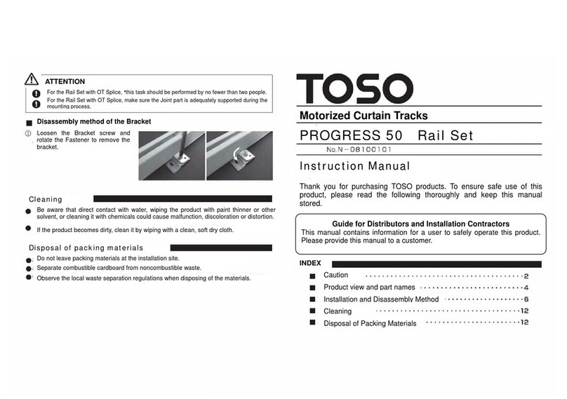
TOSO PROGRESS50 Operation instructions

PROGRESS50 Rail Set Assemble
Motorized Curtain Tracks
Assemble Manual
This manual contains information for a user to safely operate this product.
Assemble the Rail Set as described in this Manual before proceeding to the
Instruction Manual. For discussions related to using and mounting the
Product, see the Progress 50 Rail Set Instruction Manual.
Product view and part names
Disposal of Packing Materials
Cleaning
Assemble Method
Joint Method
Caution
INDEX

CAUTION
This document illustrates the dangers of using this product without taking necessary
precautions. Please refer to below symbols for different types of safety points.
CAUTION
Illustrates when misused, there are dangers of serious injuries or possible
fatal accidents.
ATTENTION
Illustrates when misused, there are dangers of casualties or possible
p
h
y
sical dama
g
e of the
p
roduct.
This document illustrates safet
y
p
oints to be ke
p
t usin
g
below s
y
mbols.
Illustrates s
p
ecific conducts which are
p
rohibited.
Illustrates specific guidelines which are enforced.
OT SpliceCeiling Single Bracket M2End side Pulley
Motor Set
(sold separately)
Stop Pilot Roller Noiseless Roller
Product view and parts names
Product view and parts names
Track Motor side Pulley

OT Splice
1 place joint x 1 pc
2 places joint x 2 pcs
Splice Pin
1 place joint x 2 pcs
2 places joint x 4 pcs
End side Pulley
X 1pc Pilot Roller Set
X 1 set ( only Two-way Draw)
Joint Plate
X 1 pc
Belt Joint
X 2 pcs
Pilot Roller fixation Screw
X 2 pcs
Master Roller Arm
X 1 pc Pilot Roller Plate
with Wheel
X 1 pc
Attached Parts
Ceiling Single Bracket
M2
Belt Joint Cover
X 2 pcs
Motor side Pulley
X 1pc
Pilot Roller
X 2 pcs
Drive Belt
X 1 pc Noiseless Roller
10 pcs / m

ATTENTION
ATTENTION
Joint Method Assemble Method
Attach the Rail before assembly.
Loosen the OT Splice Screw and insert by
sliding along the Track groove.
Inset the Splice Pin into the opening of a Track.
(If insertion is difficult, tap with a wooden
hammer or similar tool.)
Inset the other Track into the OT Splice.
(If insertion is difficult, cover the Pulley with a
cloth and tap with a wooden hammer or similar
tool.)
Position the Tracks so that the joint section is
at the center of the OT Splice, then tighten the
screws of the OT Splice.
Check to confirm that the OT Joint is securely attached to the Rail.
Do not cut the Drive Belt of the Track.
If cut, the product will not be finished to the specified width. (The Progress 50
Rail set comes with a precut Track and Drive Belt.)
Before assembly, position the
Track, Drive Belt, End side Pulley
and Motor side Pulley as shown to
the right.
Before assembl
y
Track
Belt
End side Pulley
Motor side Pulley
: Place with the groove up.
: Position so that the marked
end is on the right.
: Place on the left side.
: Place on the right side.
A
ssemble Method
Insert the Drive Belt from the
right-hand side of the Track, inserting
it all the way to the left-hand side.
(The Belt should be inserted into the
near side groove of the bottom Rail.)
Place the right end of the Drive Belt
through the End side Pulley.
(This can be done by pushing the
tip of the Drive Belt into the Pulley.)
A
ttach the Belt Joint and Belt Joint
Cover to the left end of the Drive
Belt.
A
ttach the Belt Joint to the tip of the
Belt. Attach the Belt Joint and Joint
Cover until they click into position.
Track
OT Splice
Splice Pin
①
①
①
②
②
③
③
④
E side Pulley M side Pulley
Track
Drive Belt
E side Pulley
Belt Joint
Belt Joint Cover

A
ttach the Pilot Roller to the Belt
Joint.
Insert the Pilot Roller from the
left-hand side of the Track.
For Two way-draw, attach the Pilot
Runner set to the preset Belt Joint
and insert into the track.
Insert the left side of the Track into
the End side Pulley.
Place the right end of the Drive Belt
through the Motor side Pulley.
(This can be done by pushing the
tip of the Drive Belt into the Pulley.)
A
ttach the Belt Joint and Belt Joint
Cover to the right end of the Drive
Belt.
Attach the Belt Joint so that the Belt
protrudes from the Belt Joint by the
height of one drive tooth. Attach the
Belt Joint and Joint Cover until they
click into
p
osition.
A
ttach the Pilot Roller to the Belt
Joint.
Insert the Pilot Roller from the
right-hand side of the Track.
Place the Pilot Rollers end to end.
Use the Joint Plate to join the Pilot
Rollers. Joint Plate
Belt Joint
Belt Joint
Pilot Roller
Pilot Roller Set
④
⑤
⑥
⑦
⑧
⑩
⑪
⑫
⑬
⑨
M side Pulley
Belt Joint
Belt Joint cover One drive tooth
Belt Joint
Pilot Roller

Fix Master Roller Arm and Pilot
Roller Plate with Wheel with the Pilot
Runner attachment screw.
⑭Cleaning
Be aware that direct contact with water, wiping the product with paint thinner or other
solvent, or cleaning it with chemicals could cause malfunction, discoloration or distortion.
If the product becomes dirty, clean it by wiping with a clean, soft dry cloth.
Disposal of packing materials
Do not leave packing materials at the installation site.
Separate combustible cardboard from noncombustible waste.
Observe the local waste separation regulations when disposing of the materials.
Pilot Roller Plate
M R Arm
Fixation Screw
Use a screwdriver to loosen the
screw of Stop, then remove the Stop.
⑮Stop
Insert Runners and secure the Stop
into place. (For Two way-draw, insert
the same number of Runners from
the Pulley at both ends.)
⑯
Noiseless
Roller
When securing the Stop into position, fit in such a way that the convex portion of the
Stop fits into the concave portion of the Pulley. Align carefully; an improper fit may
cause the Sto
p
to fall off.
ATTENTION
×○
The concave portion
Stop
Table of contents
Other TOSO Home Automation manuals
