Toto Link IP04229 User manual

User Manual
TOTOLINK Wireless-N Router

1
TABLE OF CONTENT
1. ABOUT THIS GUIDE.......................................................................................................3
1DYLJDWLRQRIWKH8VHU¶V*XLGH........................................................................................... 3
2. PRODUCT OVERVIEW...................................................................................................3
2.1 Introduction.......................................................................................................................... 3
2.2 Features ............................................................................................................................... 3
2.3 Panel Layout ........................................................................................................................ 4
2.3.1 Front Panel........................................................................................................................................ 4
2.3.2 Rear Panel ........................................................................................................................................ 5
3. HARDWARE INSTALLATION .........................................................................................6
3.1 Hardware Installation........................................................................................................... 6
3.2 Check the Installation.......................................................................................................... 6
3.3 Set up the Computer ........................................................................................................... 6
4. CONNECTING TO INTERNET........................................................................................8
4.1 Accessing Web page ........................................................................................................... 8
4.2 Changing Password ............................................................................................................ 9
4.3 Setup Wizard...................................................................................................................... 10
4.3.1 Router Mode ................................................................................................................................... 12
4.3.2 Wireless ISP Client Mode ............................................................................................................... 17
4.3.3 Wireless Client Mode ...................................................................................................................... 18
4.3.4 Repeater Mode ............................................................................................................................... 19
4.3.5 Bridge with AP................................................................................................................................. 21
4.3.6 Client Mode ..................................................................................................................................... 22
4.4 Status ................................................................................................................................. 22
4.4.1 System status.................................................................................................................................. 23
4.4.2 Statistics .......................................................................................................................................... 23
4.4.3 System log ...................................................................................................................................... 24
5. ADVANCED SETTINGS ................................................................................................25
5.1 TCP/IP Settings.................................................................................................................. 25
5.1.1 LAN Interface .................................................................................................................................. 25
5.1.2 WAN Interface................................................................................................................................. 27
5.1.2.1 PPPoE...................................................................................................................................... 28
5.1.2.2 PPTP ........................................................................................................................................ 29
5.1.2.3 L2TP......................................................................................................................................... 30
5.1.3 VLAN Settings................................................................................................................................. 31
5.2 Wireless.............................................................................................................................. 32
5.2.1 Basic Settings ................................................................................................................................. 32
5.2.2 Security Settings ............................................................................................................................. 36

2
5.2.3 Site Survey...................................................................................................................................... 36
5.2.4 WDS................................................................................................................................................ 37
5.2.5 Advanced Settings .......................................................................................................................... 38
5.2.6 Access Control ................................................................................................................................ 39
5.2.7 WPS Settings .................................................................................................................................. 40
5.3 Route Setup ....................................................................................................................... 40
5.3.1 Static Route..................................................................................................................................... 40
5.3.2 Routing Table .................................................................................................................................. 42
5.4 Firewall ............................................................................................................................... 42
5.4.1 IP Filtering ....................................................................................................................................... 43
5.4.2 Port Filtering.................................................................................................................................... 43
5.4.3 MAC Filtering .................................................................................................................................. 44
5.4.4 URL Filtering ................................................................................................................................... 44
5.4.5 Port Forwarding............................................................................................................................... 45
5.4.6 DMZ ................................................................................................................................................ 45
5.4.7 Denial-of-Service............................................................................................................................. 46
5.5 Management....................................................................................................................... 47
5.5.1 Upgrade Firmware .......................................................................................................................... 47
5.5.2 Save/Reload Setting ....................................................................................................................... 47
5.5.3 Web Login Password ...................................................................................................................... 48
5.5.4 TR-069 Config................................................................................................................................. 48
5.5.5 Date and Time................................................................................................................................. 49
5.5.6 Reboot Router................................................................................................................................. 50
5.6 Advanced ........................................................................................................................... 50
5.6.1 DDNS .............................................................................................................................................. 50
5.6.2 QoS ................................................................................................................................................. 51
5.6.3 Operation mode .............................................................................................................................. 52
5.6.4 SSH Server ..................................................................................................................................... 53
Copyright Statement
All the photos and product specifications mentioned in this manual are for references only, as the
upgrading of software and hardware. They are subject to change without notice. No part of the
specifications may be reproduced in any form or by any means or used to make any derivative such
as translation, transformation, or adaptation without permission from TOTOLINK. If you want to
know more about our products information, please visit our website at http://www.totolink.net
Copyrights 2013 by TOTOLINK All rights reserved.

3
1. ABOUT THIS GUIDE
Thank you very much for purchasing this router. This guide will introduce the features of this
router and tell you how to connect, use and configure the router to access Internet. Please
IROORZWKHLQVWUXFWLRQVLQWKLVJXLGHWRDYRLGDIIHFWLQJWKHURXWHU¶VSHUIRUPDQFHE\LPSURSHU
operation.
1DYLJDWLRQRIWKH8VHU¶V*XLGH
Product Overview: Describes the router¶VIXQFWLRQ and its features.
Hardware Installation: Describes the hardware installation and settings on XVHU¶V
computer.
Connecting to Internet: Tells you how to connect your computer to Internet successfully
by the router.
Advanced Settings: Lists all technical functions including Wireless, TCP/IP Settings,
Firewall and System of the router.
2. PRODUCT OVERVIEW
2.1 Introduction
This is a wireless router which integrates with internet-sharing router, 4-port switch and
firewall all-in-one. It allows users to connect to Internet by DHCP/Static IP/PPPoE(dual
access)/PPTP(dual access)/L2TP(dual access) and can deliver high speed wireless data
rate. The VLAN function also makes amazing interactive entertainment experience of IPTV
be achieved easily. Multiple encryptions including wireless LAN 64/128-bit WEP,
WPA/WPA2 and WPA-mixed security are supported by the router. The IP, Port, URL and
MAC address filtering function also makes it easy for user management. In view of the
above, it will allow you to connect your network wirelessly in an easy and secure way better
than ever. It is really a high performance and cost-effective solution for home and small
offices.
2.2 Features
¾Complies with IEEE 802.11n and IEEE 802.11g/b standards for 2.4GHz Wireless LAN.
¾Supports DHCP, Static IP, PPPoE, PPTP and L2TP broadband functions and supports
dual access.
¾Provides six operation modes: Wireless ISP Client Router, Wireless Client, Repeater,
Router, Bridge with AP and Client.
¾Connects to secure network easily and fast using WPS (one-button).
¾Provides 64/128-bit WEP, WPA/WPA2 and WPA-Mixed security.

4
¾VLAN function for IPTV or other internet services.
¾Supports IP, Port, MAC, URL filtering and Port Forwarding.
¾QoS function allocates network bandwidth reasonably.
¾Supports SSH Server function to ensure the security of remote login.
¾Setup Wizard simplifies the basic settings of the router.
2.3 Panel Layout
2.3.1 Front Panel
The front panel of this router consists of 8 LEDs, which is designed to indicate connection
status.
POWER This indicator lights blue when the router powered on, otherwise it is off.
CPU This indicator blinks blue when router powered on.
WLAN This indicator blinks blue when there are wireless devices connected and
transmitting data to the router.
WAN
On
When the WAN port is connected successfully the indicator lights blue.
Blink
During transmitting or receiving data through the WAN port the indicator
blinks blue.
Off
There is no device linked to the WAN port.

5
1/2/3/4
LAN
On When the LAN port has a successful connection, the corresponding
indicator lights blue.
Blink During transmitting or receiving data through the LAN port the
corresponding indicator blinks blue.
Off There is no device linked to the LAN port.
2.3.2 Rear Panel
The figure below shows the rear panel of this router.
Power
ON/OFF Turn on or turn off the router by the switch.
DC IN The Power socket is where you will connect the power adapter.
WAN This port is where you will connect with the cable to access Internet.
1/2/3/4 LAN This port connects the router to local PC.
RST/WPS
Button
The button is on the opposite of the rear panel. Press for about 2~3 seconds,
the system LED indicator keep solid light, it means WPS working, while press
for about 10 seconds, all LEDs blinks quickly, the device will restore to factory
default settings.

6
3. HARDWARE INSTALLATION
3.1 Hardware Installation
For those computers you wish to connect with Internet by this router, each of the computers
must be properly connected with the router through provided UTP LAN Cables.
1. &RQQHFWWKHSURYLGHG873/$1FDEOHWRRQHRIWKHURXWHU¶V/$1SRUW
2. &RQQHFWWKHRWKHUHQGRIWKH873/$1FDEOHWR\RXUFRPSXWHU¶V/$1SRUW
3. &RQQHFWWKHVHFRQG873/$1FDEOHWRURXWHU¶V:$1SRUW
4. Connect the other end of the UTP LAN cable to ADSL or Modem port.
5. Plug the Power Adapter into the router and then into an outlet.
6. Turn on your computer.
7. Check and confirm that the Power & LAN LED on the router are ON.
3.2 Check the Installation
The control LEDs of the router are clearly visible and the status of the network link can be
seen instantly:
1. With the power source on, once the device is connected to the broadband modem, the
Power, WPS, LAN, WLAN and WAN port LEDs of the WLAN Router will light up indicating
a normal status.
2. When the WAN Port is connected to Internet successfully, the WAN LED will light up.
3. When the LAN Port is connected to the computer system, the LAN LED will light up.
3.3 Set up the Computer
The default IP address of the router is 192.168.1.1, the default Subnet Mask is
255.255.255.0. Both of these parameters can be changed as you want. In this guide, we
will use the default values for description.
Connect the local PC to the LAN port on the router. There are then two ways to configure
the IP address for your PC.
Configure the IP address manually
Configure the network parameters. The IP address is 192.168.1[[[³[[[´UDQJHIURPWR
254). The Subnet Mask is 255.255.255.0 and Gateway is 192.168.1.1 (rRXWHU¶VGHIDXOW,3
address).
Obtain an IP address automatically
Set up the TCP/IP Protocol in Obtain an IP address automatically mode on your PC.
Now, you can run the Ping command in the command prompt to verify the network
connection between your PC and the router. Open a command prompt, and type in ping
192.168.1.1, then press Enter.

7
Figure 3-1 Successful Ping command
If the result displayed is similar to the figure 3-1, it means that the connection between your
PC and the router has been established.
Figure 3-2 Failure Ping command
If the result displayed is similar to the figure 3-2, it means that your PC has not connected to
the router successfully. Please check it following below steps:
1. Is the connection between your PC and the router correct?
If correct, the LAN port on the rRXWHUDQG/('RQ\RXU3&¶s adapter should be lit.
2. Is the TCP/IP configuration for your PC correct?
Since the rRXWHU¶V,3DGGUHVVLV1\RXU3&¶V,3DGGUHVVPXVWEHZLWKLQWKHUDQJH
of 192.168.1.2 ~ 192.168.1.254, the Gateway must be 192.168.1.1.

8
4. CONNECTING TO INTERNET
This chapter introduces how to configure the basic functions of your router so that you can
surf the Internet.
4.1 Accessing Web page
Connect to the router by typing 192.168.1.1 in the address field of web browser. Then press
Enter key.
Then below window will pop up that requires you to enter valid User Name and Password.
Enter admin for User Name and Password, both in lower case letters. Then click OK
button or press Enter key.
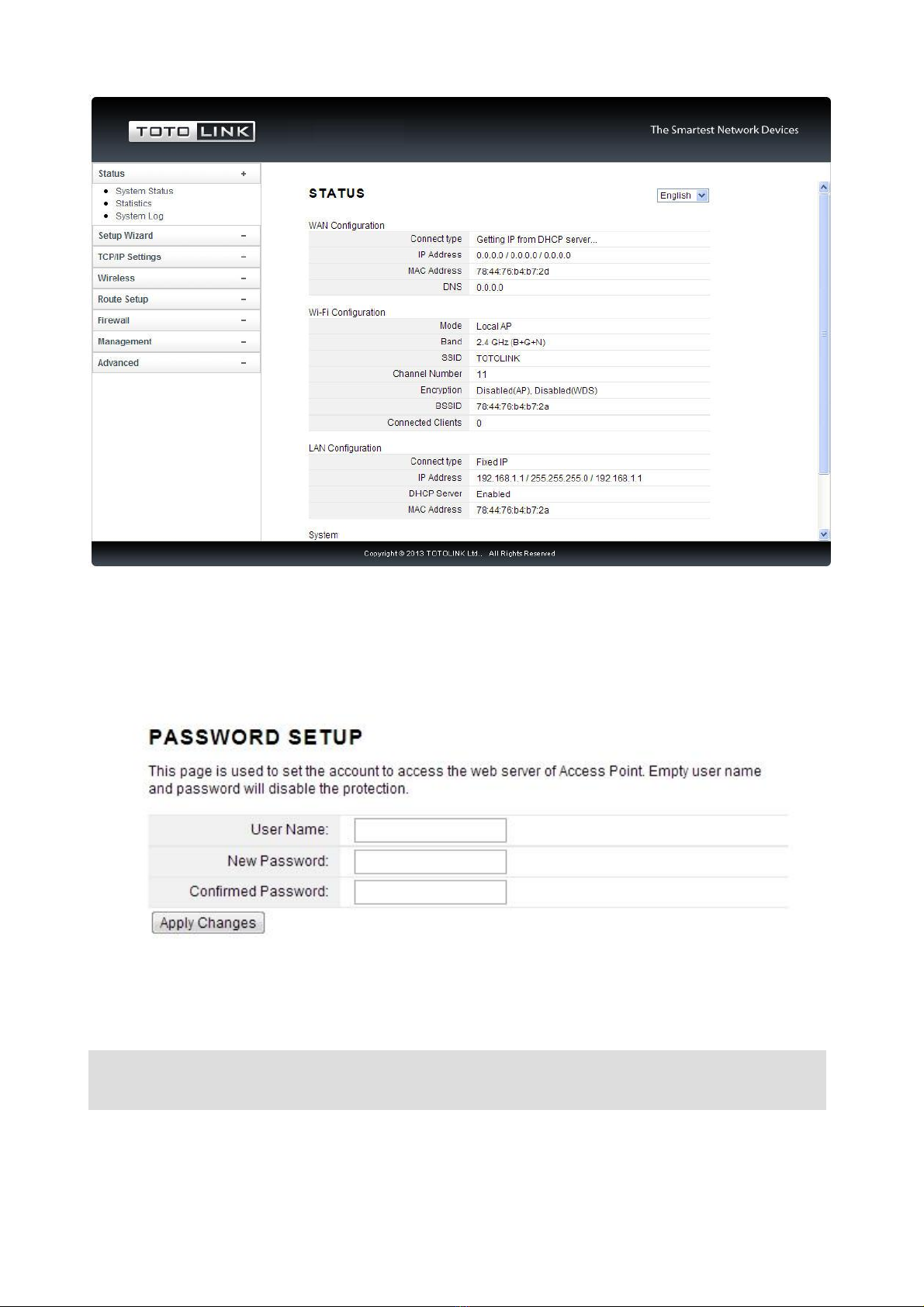
Now you will get into the web interface of the device. The Main screen will appear.
Now you have logged into the web interface of the router. First, you will see the System
Status page.
Note: If the above screen does not prompt, it means that your web-browser has been set to using a
proxy. Go to To o l s m en u >Internet Options>Connections>LAN Settings, in the screen that
appears, cancel the Using Proxy checkbox, and click OK to finish it.
9
4.2 Changing Password
Now, we recommend that you change the password to protect the security of your router.
Please go to Management²Web Login Password change the password required to log
in your router.
User Name: type in the name that you use to login the web interface of the router.
New Password: new password is used for administrator authentication.
Confirm Password: new password should be re-entered to verify its accuracy.
Note: password length is 8 characters maximum, characters after the 8th position will be truncated.
10
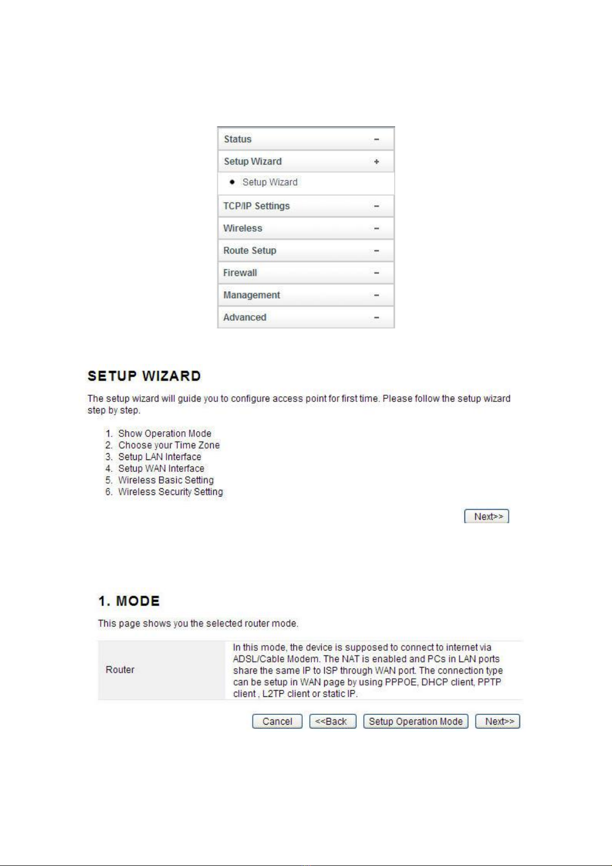
4.3 Setup Wizard
Setup Wizard is provided as part of the web configuration utility. Users can simply finish
the settings on this page to access Internet.
1. Click on the Setup Wizard on the left navigation menu, then the following screen will
appear. Click Next to continue.
2. This router provides six operation modes: Wireless ISP Client Router,Wireless Client
and Repeater (Range Extender), Router, Bridge with AP and Client. As the default
mode is Router mode, you just need to click Next to continue other settings. Otherwise,
click Setup Operation Mode Button to select one operation mode according to need.
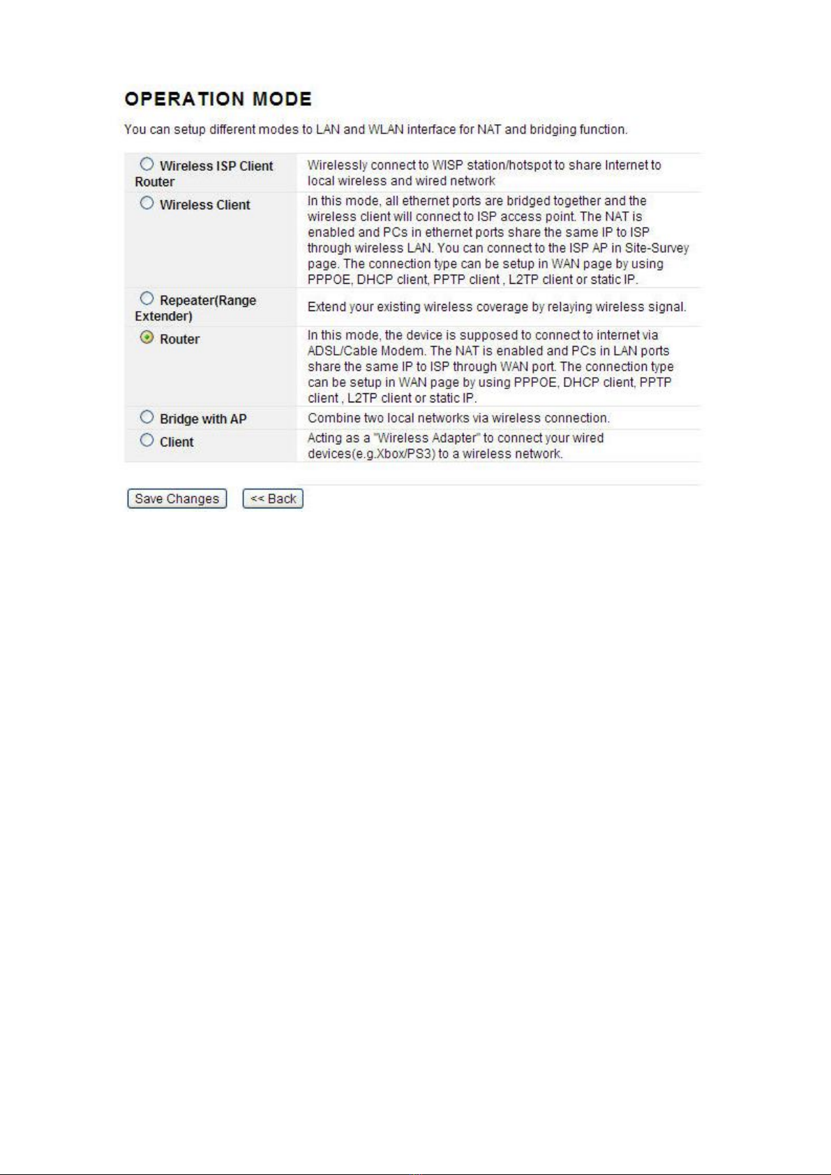
3. After click Setup Operation Mode Button, the operation mode select interface will appear,
please choose the proper mode refer to the introduction. Click Save Changes.
11
A: Wireless ISP Client Router
In this mode, it will wirelessly connect to WISP station/hotspot to share Internet to local
wireless and wired network.
B: Wireless Client
In this mode, all Ethernet ports are bridged together and the wireless client will connect to
ISP access point. The NAT is enabled and PCs in Ethernet ports share the same IP to ISP
through wireless LAN. You can connect to the ISP AP in Site-Survey page. The connection
type can be setup in WAN page by using PPPOE, DHCP client, PPTP client, L2TP client or
static IP.
C: Repeater (Range Extender)
In this mode, the device can copy and reinforce the existing wireless signal to extend the
coverage of the signal, especially for a large space to eliminate signal-blind corners. It is
good for extending your existing wireless coverage by relaying wireless signal.
D: Router
In this mode, the device enables multi-users to share Internet via ADSL/Cable Modem. The
Wireless port share the same IP to ISP through Ethernet WAN port .The Wireless port acts
the same as a LAN port while at AP Router mode. The connection type can be setup in
WAN page by using PPPOE, DHCP client, PPTP client, L2TP client or static IP.
E: Bridge with AP
In this mode, the device can be used to combine multiple local networks together to the
12
same one via wireless connections, especially for a home or office where separated
networks FDQ¶W be connected easily together with a cable.
F: Client
In this mode, the device can be connected to another device via Ethernet port and act as a
"Wireless Adapter" to connect your wired device to a wireless network.
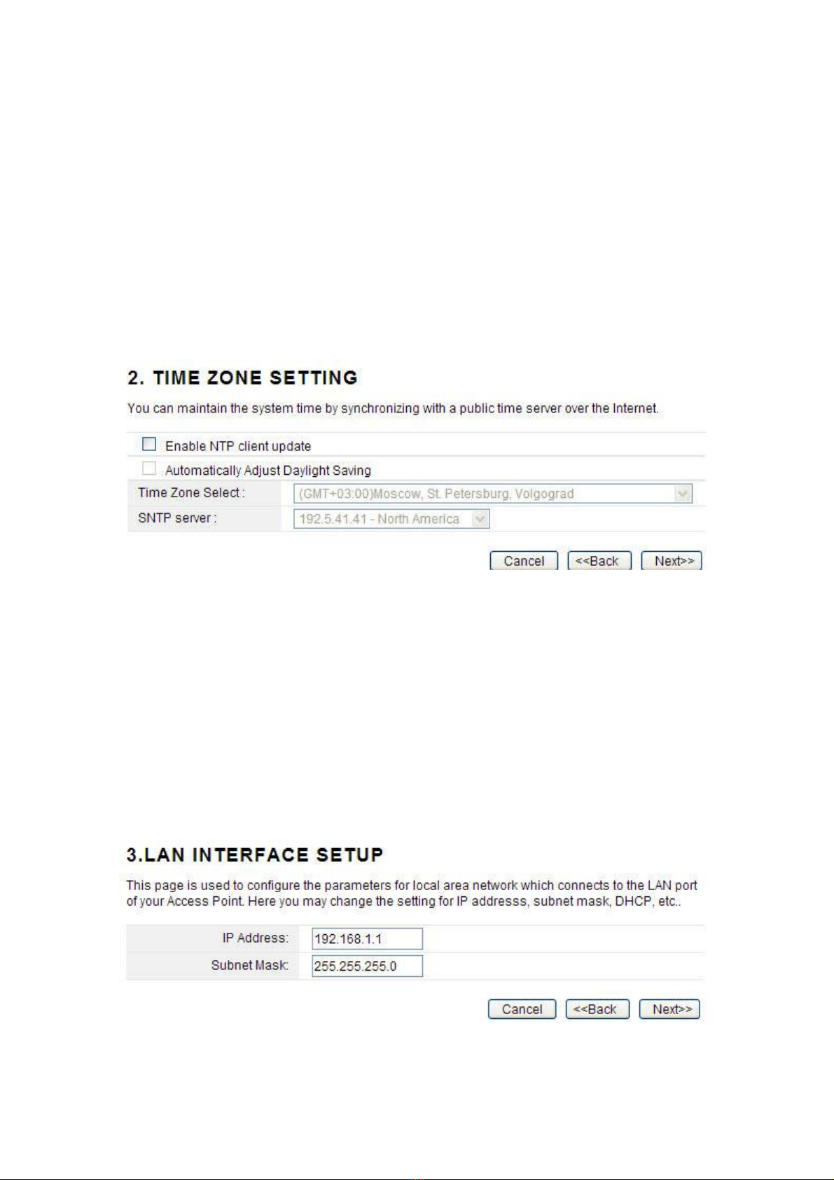
4.3.1 Router Mode
After selecting the Router mode in the last step, click next to continue the other settings.
1. This page allows you to maintain the system time synchronizing with a public time server
over the Internet. +HUH \RX FDQ VSHFLI\ WKH GHYLFH¶V WLPH ]RQH DFFRUGing to GMT
(Greenwich Mean Time). Then click Next.
Enable NTP client update: NTP means Network Time Protocol which is used to make the
computer¶V time synchronized with its server or clock source, such as Quartz and GPS. It
can provide high-precision time correction and prevent harmful protocol attack by
confirming encryption. You need to check this box to activate this page.
Automatically Adjust Daylight Saving: If the Time Zone you choose implements daylight
saving time, please select this option.
Time Zone Select: Select the Time Zone where the router is located.
SNTP server: Please choose the corresponding SNTP server to get right time.
2. This page is used to configure the parameters for local area network which connects to
the LAN port of your Access Point.
IP Address: this is the IP address to be represented by the LAN (including WLAN)
interface that is connected to the internal network. This IP will be used for the routing of the
internal network (it will be the Gateway IP for all the devices connected on the internal
13
network).
Subnet Mask: this is used to define the device IP classification for the chosen IP address
range. 255.255.255.0 is a typical netmask value for Class C networks which support IP
address range from 192.0.0.x to 223.255.255.x. Class C network netmask uses 24 bits to
identify the network and 8 bits to identify the host.
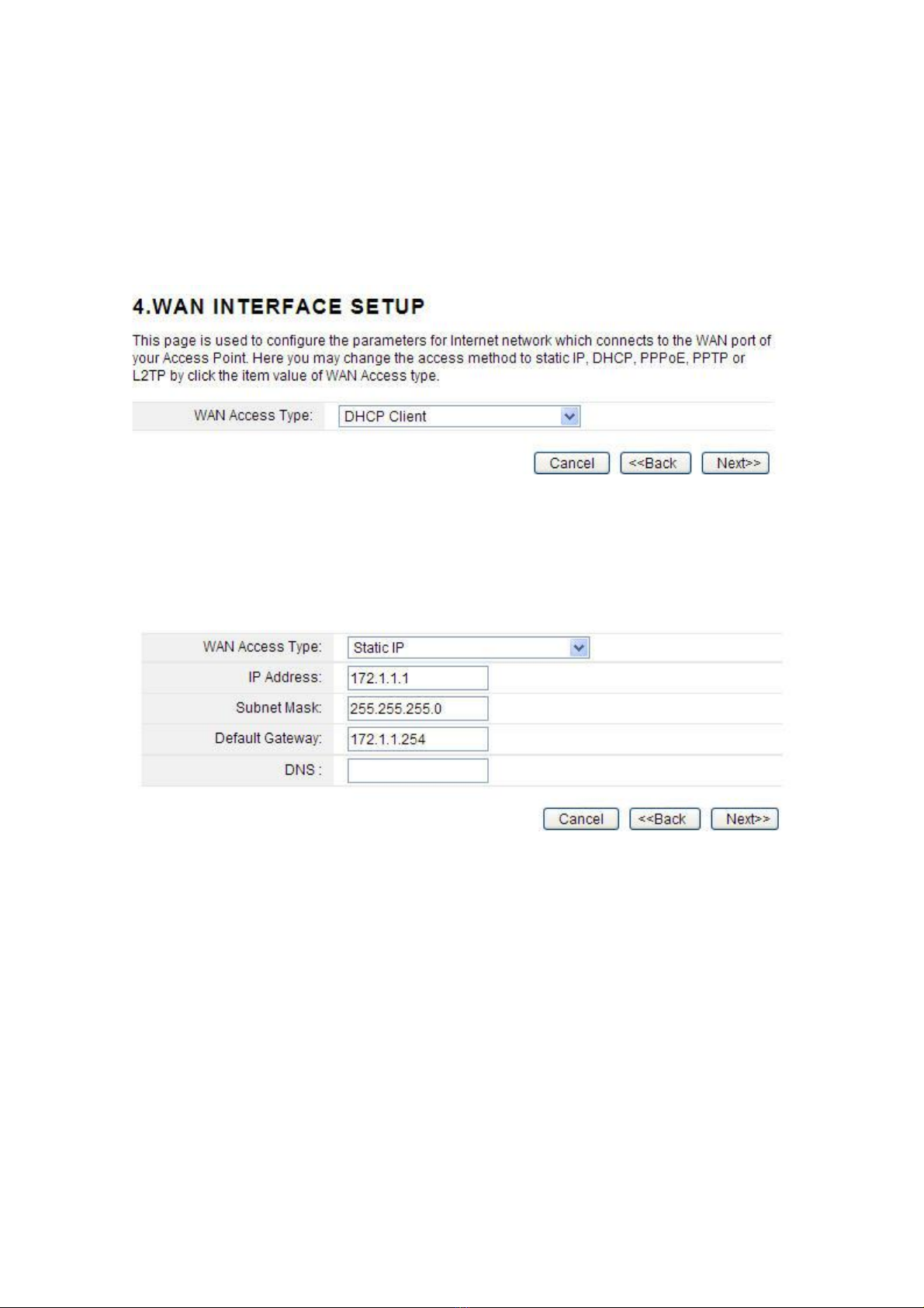
3. This interface is used to configure the parameters for Internet network which connects to
the WAN port of your Access Point.
WAN Access Type: there are three methods provided to allow you to access Internet.
Please choose the appropriate one according to the information from your ISP (Internet
Service Provider).
(1). Static IP
If your ISP has provided the fixed IP that allows you to access Internet, please choose this
option.
IP Address: the IP address provided by your ISP.
Subnet Mask: This is used to define the device IP classification for the chosen IP address
range. 255.255.255.0 is a typical net mask value for Class C networks. Generally it is
provided by your ISP.
Default Gateway: This is the IP address of the host router that resides on the external
network and provides the point of connection to the next hop towards the Internet. This can
be a DSL modem, Cable modem, or a WISP gateway router. The router will direct all the
packets to the gateway if the destination host is not within the local network.
DNS: 7KH 'RPDLQ 1DPH 6\VWHP '16 LV DQ ,QWHUQHW ³SKRQH ERRN´ ZKLFK WUDQVODWHV
domain names to IP addresses. These fields identify the server IP addresses where the
DNS requested are forwarded by this router.
(2). DHCP
Dynamic Host Configuration Protocol (DHCP) is a local area network protocol. If you
choose this mode, you will get a dynamic IP address from your ISP automatically.

14
(3). PPPoE
Point-to-Point Protocol over Ethernet (PPPoE) is a virtual private and secure connection
between two systems that enables encapsulated data transport. It replied on two widely
accepted standards: PPP and Ethernet. The router supports dual access in this WAN type,
you could choose the proper one according to what your ISP provides for you.
User Name: a specific valid ADSL user name provided by your ISP.
Password: the corresponding valid password provided by your ISP.
(4). PPTP
PPTP means Point to Point Tunneling Protocol is a VPN connection that only applies in
Europe. If you choose one of them, please type in all the information that your ISP provided
for this protocol:
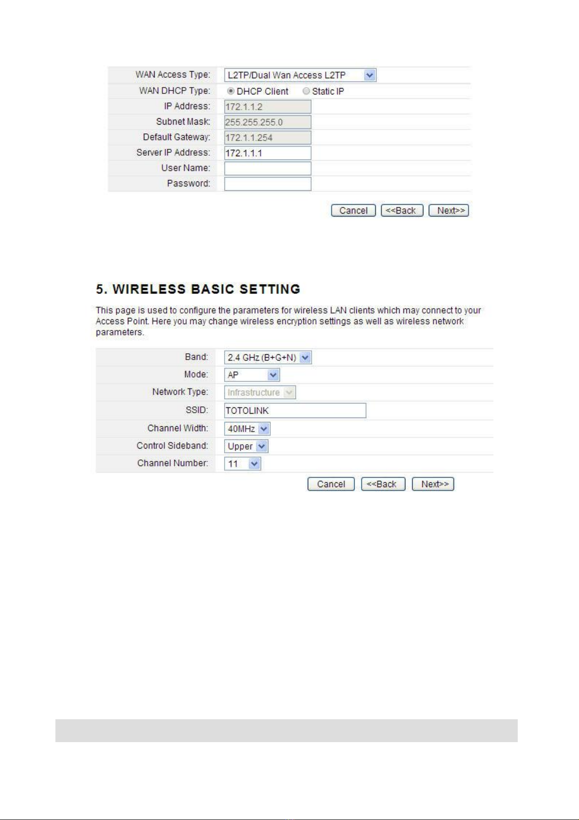
(5). L2TP
L2TP means Layer 2 Tunneling Protocol is a VPN connection that only applies in Europe,
Middle East and Africa (MEA) regions. If you choose one of them, please type in all the
information that your ISP provided for this protocol:
15
4. The general wireless settings, such as wireless mode, SSID and channel can be
configured in this section.
Band
˖
In fact, this option allows you to choose the radio standard for operation of your
router. 802.11b and 802.11g are old 2.4GHz mode, while 802.11n (2.4GHz and/or 5GHz, in
this case, only supports 2.4GHz) is the latest standard based on faster Orthogonal
Frequency Division Multiplexing (OFDM) modulation. Here, you can choose the last one
2.4GHz (B+G+N), this mode offers better compatibility.
Mode
˖
Wireless mode specifies the operating mode of the device. The mode depends on
the network topology requirements. There are 2 operating modes supported in this
software.
AP: 7KLV PRGH DOORZV XVHUV ZLWK ODSWRS WR VXUI ,QWHUQHW E\ ZLUHOHVV FRQQHFWLRQ ,W¶V
designed to add wireless function for existed wired router which is just suitable for
home and small offices.
Client: ,I \RX FKRRVH WKLV PRGH WKH &KDQQHO 1XPEHU DQG &KDQQHO :LGWK FDQ¶W EH
edited.
Note: ,I\RXVHOHFW:'6\RXFDQ¶Wchange SSID.

16
SSID---Service Set Identifier used to identify your 802.11 wireless LAN should be specified
while operating in AP or AP+WDS mode. All the client devices within the range will receive
broadcast messages from the access point advertising this SSID.
Channel Width---This is the spectral width of the radio channel. Supported wireless
channel spectrum widths:
20MHz is the standard channel spectrum width.
40MHz is the channel spectrum with the width of 40MHz (selected by default).
Control Sideband---This function is to control the sideband of the radio channel.
Upper: By default, it is Upper, and the Channel Number is 11.
Lower: If you choose Lower, the Channel Number will change to Auto automatically
DQG\RXFDQ¶WFKDQJHWKH&RQWURO6LGHEDQGDWWKHVDPHWLPH7KHVHOHFWDEOH&KDQQHO
Number now will range from 1 to 9. Only when you choose other Channel Number you
will activate the Control Sideband again. If you choose Upper, the Channel Number
selectable will range from 5 to 13.
Channel Number---this option provides selectable channel numbers.
5. For a secure connection, WPA2 Mixed is recommended for you to protect your network.
After all the above settings, please click Finish button, then page with below messages will
pop up:
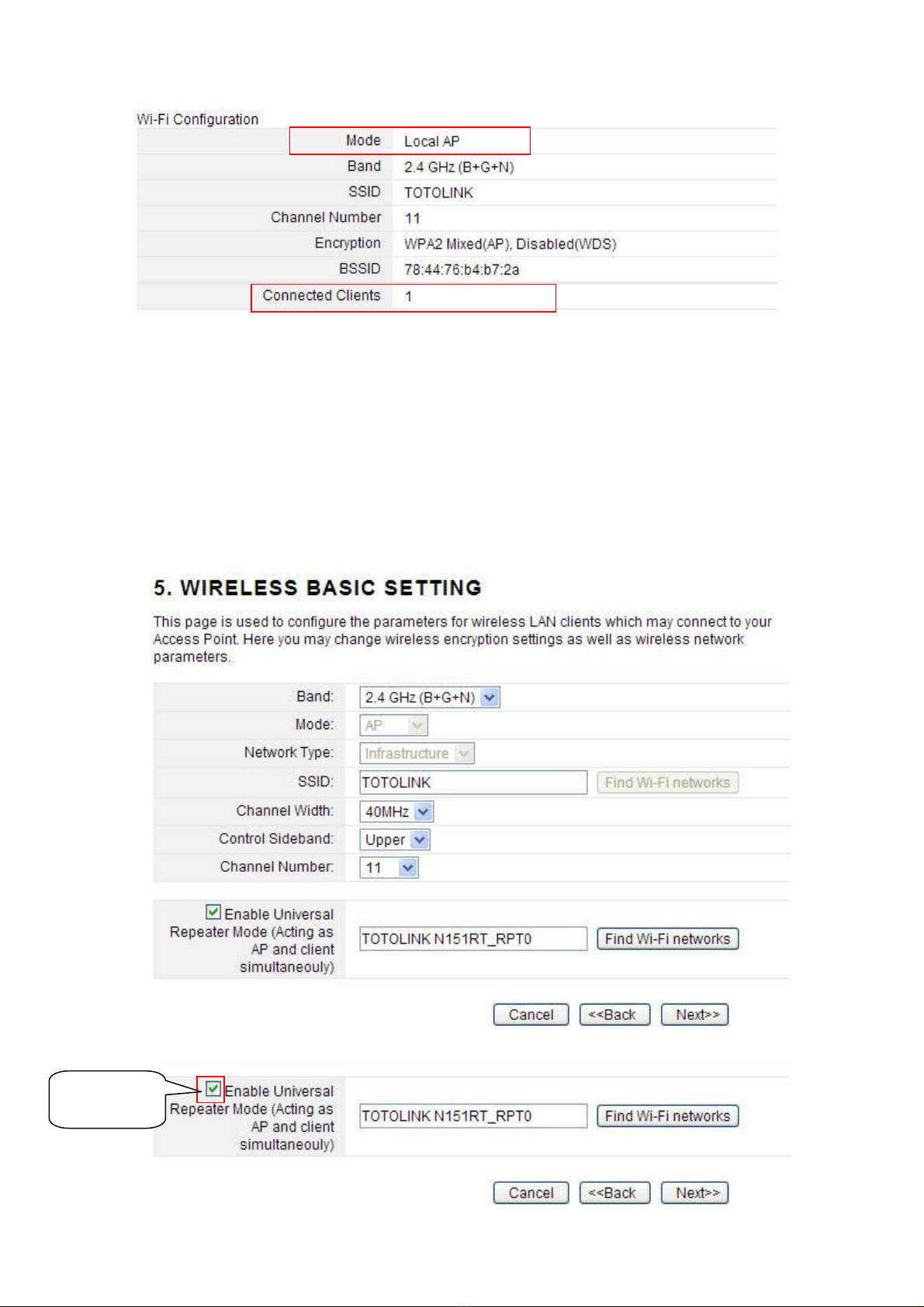
When it turns back to the system status interface, you can see the Wi-Fi Configuration
Column, The Mode should be Local IP if you have setup Router mode successfully. The
numbers of connected clients will be shown here. Now you can surf Internet and enjoy the
best wireless experience brought by the router.
17
4.3.2 Wireless ISP Client Mode
1. In the Wireless ISP Client Mode, the Time Zone Setting is the same with the Router
mode.
2. The LAN and WAN Interface Setting is the same with the Router mode too.
3. The wireless basic setting interface is obviously different from the Router mode.
In this mode, you can enable Universal Repeater in this page.
,I\RXGRQ¶WZDQWWRHQDEOHWKH8QLYHUVDO5HSHDWHU0RGHVHHEHORZ
Click Here
18
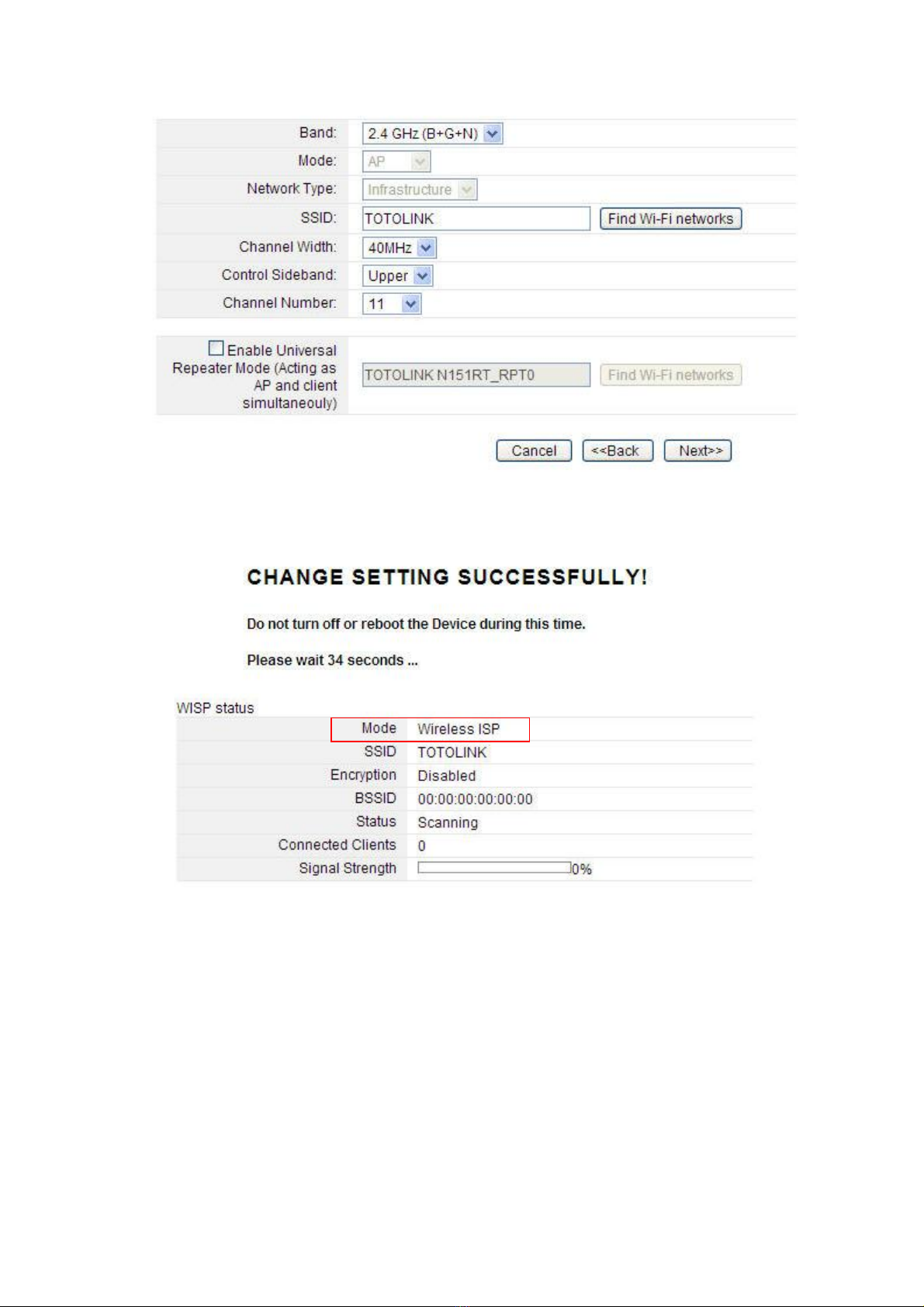
After that disable the Universal Repeater Mode, the page will change, see below:
4. The settings will take effect soon. Then it will come back to the system status interface,
and you can see the WISP status. The signal strength is also shown here.
4.3.3 Wireless Client Mode
The first three steps are the same with Router mode too. Wireless Basic Setting interface is
also different with the Router mode. See below.
Please

19
After configuration, it will also come back to the system status interface, and you can see
the Wi-Fi Configuration column. The signal strength is also shown here.
4.3.4 Repeater Mode
1. In the Repeater Mode, the Time Zone Setting is the same with the Router Mode.
2. The LAN Interface Setting is the same with the Router Mode too.
3. The WAN interface setting is unvalued in Repeater Mode. See Below:
4. Wireless Basic Setting interface is also different with the Router mode. See below:
Table of contents
Other Toto Link Network Router manuals


Popular Network Router manuals by other brands

TRENDnet
TRENDnet TEW-231BRP Quick installation guide

Cisco
Cisco ASR 9001 Hardware installation guide

Peak
Peak PCAN-Router Pro user manual

Lantronix
Lantronix Maestro E220 Series user guide

B&B Electronics
B&B Electronics Elinx EIR505 Series quick start guide

HARTING
HARTING Ha-VIS FTS 3100s-A Installation notes for electrical personnel


TP-Link
TP-Link SafeStream TL-R605 installation guide

ZyXEL Communications
ZyXEL Communications LTE Series user guide

SEOWON INTECH
SEOWON INTECH WiMAX SWC-5100W user manual

Gearlinx
Gearlinx NR4400 Series User's quick start guide

Carson
Carson Reflex Wheel Ultimate Touch 2.4g instruction manual

TP-Link
TP-Link TL-WDR3600 Specifications