Toto Link A850 User manual

1
Table of Contents
1. ABOUT THIS GUIDE...................................................................................................................3
1.1 Navigation of the User’s Guide............................................................................................................. 3
2. PRODUCT OVERVIEW ..............................................................................................................3
2.1 Introduction............................................................................................................................................ 3
2.2 Features .................................................................................................................................................. 3
2.3 Panel Layout .......................................................................................................................................... 4
2.3.1 Front Panel ........................................................................................................................................................4
3. HARDWARE INSTALLATION...................................................................................................5
3.1 Hardware Installation........................................................................................................................... 5
3.2 Check the Installation............................................................................................................................ 5
3.3 Set up the Computer.............................................................................................................................. 6
4. CONNECTING TO INTERNET..................................................................................................7
4.1 Accessing Web page............................................................................................................................... 7
4.2 Changing Password............................................................................................................................... 9
4.3 Status....................................................................................................................................................... 9
4.4 Operation Mode....................................................................................................................................11
4.5 Network ................................................................................................................................................ 12
4.5.1 WAN Settings..................................................................................................................................................12
4.5.1.1 Static IP....................................................................................................................................................13
4.5.1.2 DHCP Client ............................................................................................................................................14
4.5.1.3 PPPoE.......................................................................................................................................................14
4.5.1.4 PPTP.........................................................................................................................................................15
4.5.1.5 L2TP.........................................................................................................................................................16
4.5.2 LAN Settings...................................................................................................................................................17
4.5.3 Static DHCP Settings.......................................................................................................................................18
4.5.4 VLAN Settings................................................................................................................................................19
4.6 Wireless 5GHZ..................................................................................................................................... 21
4.6.1 Basic Settings ..................................................................................................................................................21
4.6.2 Wireless AP1 ...................................................................................................................................................24
4.6.3 Wireless AP2 ...................................................................................................................................................26
4.6.4 Wireless Repeater............................................................................................................................................29
4.6.5 Advanced Settings...........................................................................................................................................29
4.6.6 WDS Settings ..................................................................................................................................................31
4.6.7 Access Control.................................................................................................................................................32
4.6.8 WPS Settings...................................................................................................................................................33
4.6.9 Wireless Schedule............................................................................................................................................33
4.7 Wireless 2.4GHZ.................................................................................................................................. 34

2
4.7.1 Basic Settings ..................................................................................................................................................34
4.7.2 Wireless AP1 ...................................................................................................................................................37
4.7.3 Wireless AP2 ...................................................................................................................................................40
4.7.4 Wireless Repeater............................................................................................................................................42
4.7.5 Advanced Settings...........................................................................................................................................42
4.7.6 WDS Settings ..................................................................................................................................................44
4.7.7 Access Control.................................................................................................................................................45
4.7.8 WPS Settings...................................................................................................................................................46
4.7.9 Wireless Schedule............................................................................................................................................46
4.8 QoS........................................................................................................................................................ 47
4.9 Firewall................................................................................................................................................. 48
4.9.1 IP Filtering.......................................................................................................................................................48
4.9.2 Port Filtering....................................................................................................................................................49
4.9.3 MAC Filtering.................................................................................................................................................49
4.9.4 URL Filtering ..................................................................................................................................................50
4.9.5 Port Forwarding...............................................................................................................................................50
4.9.6 DMZ................................................................................................................................................................51
4.10 Management....................................................................................................................................... 51
4.10.1 DDNS Settings..............................................................................................................................................51
4.10.2 Upgrade Firmware.........................................................................................................................................52
4.10.3 Reload Factory Settings.................................................................................................................................52
4.10.4 Password Settings..........................................................................................................................................53
4.10.5 Time Zone Setting.........................................................................................................................................53
4.10.6 Reboot Router................................................................................................................................................54
4.10.7 Schedule Reboot............................................................................................................................................54
4.10.8 System Log....................................................................................................................................................54
Copyright Statement
All the photos and product specifications mentioned in this manual are for references only, as the
upgrading of software and hardware. They are subject to change without notice. No part of the
specifications may be reproduced in any form or by any means or used to make any derivative such
as translation, transformation, or adaptation without permission from TOTOLINK. If you want to
know more about our products information, please visit our website at http://www.totolink.net
Copyrights 2014 by TOTOLINKAll rights reserved.

3
1. ABOUT THIS GUIDE
Thank you very much for purchasing the wireless N router. This guide will introduce the
features of this router and tell you how to connect, use and configure the router to access
Internet. Please follow the instructions in this guide to avoid affecting the router’s
performance by improper operation.
1.1 Navigation of the User’s Guide
Product Overview: Describes the router’s function and its features.
Hardware Installation: Describes the hardware installation and settings on user’s
computer.
Connecting to Internet:Tells you how to connect your computer to Internet successfully
by the router.
Advanced Settings:Lists all technical functions including Wireless, TCP/IP Settings,
Firewall and System of the router.
2. PRODUCT OVERVIEW
2.1 Introduction
This is a wireless router which integrates with internet-sharing router, 4-port switch and
firewall all-in-one. Multiple encryptions including wireless LAN 64/128-bit WEP, WPA/WPA2
and WPA-mixed security are supported by the router. The VLAN function also makes
amazing interactive entertainment experience of IPTV be achieved easily. The IP, Port,
URL and MAC address filtering function also makes it easy for user management. In view
of the above, it will allow you to connect your network wirelessly in an easy and secure way
better than ever. It is really a high performance and cost-effective solution for home and
small offices.
2.2 Features
Complies with IEEE 802.11ac/a/b/g/n standards.
Delivers 300Mbps data rate on 2.4GHz and 867Mbps on 5GHz simultaneously.
Advanced MIMO technology ensures greater range and increasing throughput.
Supports DHCP, Static IP, PPPoE, PPTP and L2TP broadband functions.
Supports dual access while WAN type is PPPoE, PPTP or L2TP.
Provides 64/128-bit WEP, WPA, WPA2 and WPA/WPA2(TKIP+AES) security.
Connects to secure network easily and fast using WPS (one-button).
Supports IP, MAC, URL filtering and Port Forwarding.

4
Universal repeater and WDS make WiFi extension simple.
2.3 Panel Layout
2.3.1 Front Panel
The front panel of this router consists of 10 LEDs, which is designed to indicate connection
status.
POWER This indicator lights blue when the router powered on, otherwise it is off.
CPU When the router powered on, this indicator keeps lighting blue.
2.4G This indicator lights blue when the 2.4G wireless connection enabled.
5G This indicator lights blue when the 5G wireless connection enabled.
WAN When the WAN port is connected successfully the indicator lights blue.
While transmitting or receiving data through the WAN port the indicator blinks blue.
1/2/3/4 LAN
When the LAN port has a successful connection, the indicator lights blue.
While transmitting or receiving data through the LAN port the indicator blinks blue.
The figure below shows the rear panel of this router.

5
DC IN This socket is used to connect the power adapter.
ON/OFF This slide switch is used to power on or off the wireless router.
1/2/3/4 LAN This port is used to connect the router to local PC.
WAN This port is used to connect the router to the Internet.
RST-WPS There is a RST-WPS button on
the rear panel. Press the button for more than 5
seconds, the router will restore factory settings. If press the button less than 5
seconds, the router will establish Wi-Fi protected settings automatically.
3. HARDWARE INSTALLATION
3.1 Hardware Installation
For those computers you wish to connect with Internet by this router, each of the computers
must be properly connected with the router through provided Ethernet cables.
1. Connect the Modem to ADSL Filter using RJ11 network cable, LINE port to LINE port.
2. Connect the ADSL’s LAN port to Router’s WAN port using RJ45 network cable.
3. Connect your PC to any one of router’s LAN port.
4. Plug the Power Adapter into the router and then into an outlet.
5. Turn on your computer.
6. Check and confirm that the Power & LAN LED on the router are ON.
3.2 Check the Installation
The control LEDs of the router are clearly visible and the status of the network link can be
seen instantly:
1. With the power source on, once the device is connected to the broadband modem, the
Power, WPS, LAN, WLAN and WAN port LEDs of the WLAN Router will light up indicating
a normal status.
2. When the WAN Port is connected to Internet successfully, the WAN LED will light up.
3. When the LAN Port is connected to the computer system, the LAN LED will light up.

6
3.3 Set up the Computer
The default IP address of the router is 192.168.1.1, the default Subnet Mask is
255.255.255.0. Both of these parameters can be changed as you want. In this guide, we
will use the default values for description.
Connect the local PC to the LAN port on the router. There are then two ways to configure
the IP address for your PC.
Configure the IP address manually
Configure the network parameters. The IP address is 192.168.1.xxx (“xxx” range from 2 to
254). The Subnet Mask is 255.255.255.0 and Gateway is 192.168.1.1 (router’s default IP
address).
Obtain an IP address automatically
Set up the TCP/IP Protocol in Obtain an IP address automatically mode on your PC.
Now, you can run the Ping command in the command prompt to verify the network
connection between your PC and the router. Open a command prompt, and type in ping
192.168.1.1, then press Enter.
Figure 3-1 Successful Ping command
If the result displayed is similar to the figure 3-1, it means that the connection between your
PC and the router has been established.

7
Figure 3-2 Failure Ping command
If the result displayed is similar to the figure 3-2, it means that your PC has not connected to
the routersuccessfully. Please check it following below steps:
1. Is the connection between your PC and the router correct?
If correct, the LAN port on the router and LED on your PC’s adapter should be lit.
2. Is the TCP/IP configuration for your PC correct?
Since the router’s IP address is 192.168.1.1, your PC’s IP address must be within the range
of 192.168.1.2 ~ 192.168.1.254, the Gateway must be 192.168.1.1.
4. CONNECTING TO INTERNET
This chapter introduces how to configure the basic functions of your router so that you can
surf the Internet.
4.1 Accessing Web page
Connect to the router by typing 192.168.1.1 in the address field of web browser. Then press
Enter key.
Then below window will pop up that requires you to enter valid User Name and Password.

8
Enter admin for User Name and Password, both in lower case letters. Then click OK
button or press Enter key.
Now you will get into the web interface of the device. The Main screen will appear.
Now you have logged into the web interface of the router. First, you will see the Easy Setup
page.
Note: If the above screen does not prompt, it means that your web-browser has been set to using a
proxy. Go to Tools menu>Internet Options>Connections>LAN Settings, in the screen that
appears, cancel the Using Proxy checkbox, and click OK to finish it.

9
4.2 Changing Password
Now, we recommend that you change the password to protect the security of your router.
Please go to Management—Password to change the password required to log in your
router.
User Name: type in the name that you use to login the web interface of the router.
New Password: new password is used for administrator authentication.
Confirm Password:new password should be re-entered to verify its accuracy.
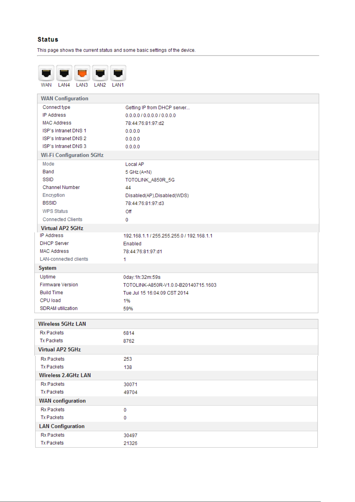
4.3 Status
This page shows the current status and some basic parameters of the device.
Note: password length is 8 characters maximum, characters after the 8
th
position will be truncated.
10

11
4.4 Operation Mode
This parameter specifies the operating network modes for the Router. This router provides
three modes: Gateway Mode, Bridge Mode and Wireless ISP. You could refer to the
following description to choose the right one.
1. Wireless ISP Client Router
In this mode, it will wirelessly connect to WISP station/hotspot to share Internet to local
wireless and wired network.
2. Wireless Client
In this mode, all Ethernet ports are bridged together and the wireless client will connect to
ISP access point. The NAT is enabled and PCs in Ethernet ports share the same IP to ISP
through wireless LAN. You can connect to the ISP AP in Site-Survey page. The connection
type can be setup in WAN page by using PPPOE, DHCP client, PPTP client, L2TP client or
static IP.
3. Repeater (Range Extender)
In this mode, the device can copy and reinforce the existing wireless signal to extend the
coverage of the signal, especially for a large space to eliminate signal-blind corners. It is
good for extending your existing wireless coverage by relaying wireless signal.
4. Router
In this mode, the device enables multi-users to share Internet via ADSL/Cable Modem. The
Wireless port share the same IP to ISP through Ethernet WAN port .The Wireless port acts
the same as a LAN port while atAP Router mode. The connection type can be setup in
WAN page by using PPPOE, DHCP client, PPTP client, L2TP client or static IP.
5. Bridge with AP
In this mode, the device can be used to combine multiple local networks together to the
same one via wireless connections, especially for a home or office where separated
networks can’t be connected easily together with a cable.
6. Client
In this mode, the device can be connected to another device via Ethernet port and act as a
"WirelessAdapter" to connect your wired device to a wireless network.

12
4.5 Network
4.5.1 WAN Settings
This part allows you to configure the WAN port parameters so that your computer can
access Internet.
Enable UPNP: the UPNP (Universal Plug and play) protocol is supported to bring to
network connected devices the ease of installation and configuration which is already
available for directly connected PC peripherals with the existing Windows “Plug and Play”
system. You can enable this function so that the router doesn’t need to work out which port
need to be opened.
Enable IGMP Proxy: IGMP is the abbreviation of Internet Group Management Protocol. It
is a communication protocol which is mainly used for managing the membership of Internet
Protocol multicast groups. If you select this checkbox, the application of multicast will be
executed through WAN port. In addition, such function is available in NAT mode.
Enable Ping Access on WAN: enable users use Ping command to access WAN.
Enable Web Server Access on WAN: enable users to access Web Server on WAN.

13
Enable IPsec pass through on VPN connection: IPsec pass through is a technique for
allowing IPsec packets to pass through a NAT router.
Enable PPTP pass through on VPN connection: PPTP pass through is a technique for
allowing PPTP packets to pass through a NAT router.
Enable L2TP pass through on VPN connection: L2TP pass through is a technique for
allowing L2TP packets to pass through a NAT router.
Clone MAC Address: MAC address is the physical address of your computer’s network
card. Generally, every network card has one unique Mac address. Since many ISPs only
allow one computer in LAN to access Internet, users can enable this function to make more
computers surf Internet.
4.5.1.1 Static IP
If your ISP has provided the fixed IP that allows you to access Internet, please choose this
option.
IP Address: the IP address provided by your ISP.
Subnet Mask: This is used to define the device IP classification for the chosen IP address
range. 255.255.255.0 is a typical net mask value for Class C networks. Generally it is
provided by your ISP.
Default Gateway: This is the IP address of the host router that resides on the external
network and provides the point of connection to the next hop towards the Internet. This can

14
be a DSL modem, Cable modem, or a WISP gateway router. The router will direct all the
packets to the gateway if the destination host is not within the local network.
MTU: it means Max Transmit Unit for packet. When using slow links, large packets can
cause some delays thereby increasing lag and latency.
DNS: The Domain Name System (DNS) is an Internet “phone book”, which translates
domain names to IP addresses. These fields identify the server IP addresses where the
DNS requested are forwarded by this router.
4.5.1.2 DHCP Client
Dynamic Host Configuration Protocol (DHCP) is a local area network protocol. If you
choose this mode, you will get a dynamic IP address from your ISP automatically.
Host Name: the name of your computer, online neighbors will identify the computer
according to the name.
MTU: it means Max Transmit Unit for packet. When using slow links, large packets can
cause some delays thereby increasing lag and latency.
DNS: Domain Name System. Every Internet host must have a unique IP address, also they
may have a human-friendly, easy to remember name such as www.yahoo.com. The DNS
server converts the user-friendly name into its equivalent IP address.
4.5.1.3 PPPoE
Point-to-Point Protocol over Ethernet (PPPoE) is a virtual private and secure connection
between two systems that enables encapsulated data transport. Select PPPoE option if ISP
provides a PPPoE connection. You should enter the following parameters.

15
User Name/Password: enter the User Name and Password provided by your ISP.
Service Name (AC): this is optional. It describes the service name your ISP provided to
you. Generally, leaving these fields blank will work.
DNS: Domain Name System. If you select Set DNS Manually, you will have to type in the
DNS address by yourself. It is chosen to Attain DNS by default.
Connection Type: provides three modes to connect to the Internet.
Continuous: the connection can be re-established automatically.
Connection on demand: the Internet connection can be terminated automatically after
a specified inactivity period (idle time).
Manual:you can click Connect or Disconnect button to connect/disconnect
immediately.
Idle Time: it is a term which generally refers to a lack of motion or energy.
MTU: it means Max Transmit Unit for packet. When using slow links, large packets can
cause some delays thereby increasing lag and latency.
4.5.1.4 PPTP
You should select PPTP option if ISP provides a PPTP connection and enter the following

16
parameters. Please refer to PPPoE configuration if there are the same parameters.
MPPE: You can enable MPPE Encryption or MPPC compression here. MPPE provides link
encryption. Link encryption encrypts data as it passes between the calling and answering
routers. MPPC provides a method to negotiate and utilize compression protocols over PPP
encapsulated links.
WAN DHCP type: it’s available only for PPTP connection. If your ISP provides an extra
type to connect to a local area network such as DHCP Client/Static IP,you should select
the type and enter the right parameters provided by ISP to enable the secondary
connection.
DNS Type: If you select Set DNS Manually, you will have to type in the DNS address by
yourself. It is chosen to Attain DNS by default while you select the DHCP client mode.
Besides, it is Set DNS type while you select the Static IP.
4.5.1.5 L2TP
You should select L2TP option if ISP provides a L2TP connection and enter the following

17
parameters. Please refer to PPPoE configuration if there are the same parameters.
4.5.2 LAN Settings
LocalArea Network (LAN) is a group of subnets regulated and ruled by router. The design
of network structure is related to what type of public IP addresses coming from your ISP.
This part allows you to configure the parameters for LAN which connects to the LAN port of
your Access Point.

18
IP Address: This is the IP addresses to be represented by the LAN (including WLAN)
interface that is connected to the internal network. This IP will be used for the routing of the
internal network (it will be the Gateway IP for all the devices connected on the internal
network).
Subnet Mask: This is used to define the device IP classification for the chosen IP address
range. 255.255.255.0 is a typical netmask value for Class C networks which support IP
address range from 192.0.0.x to 223.255.255.x. Class C network netmask uses 24 bits to
identify the network and 8 bits to identify the host.
Default Gateway: This is the IP address of the host router that resides on the external
network and provides the point of connection to the next hop towards the Internet. This can
be a DSL modem, Cable modem, or a WISP gateway router. The router will direct all the
packets to the gateway if the destination host is not within the local network.
DHCP: You can disable or enable DHCP Server here.
DHCP Client Range: the range of IP addresses that will be assigned to each computer
connected with the router.
DHCP Lease Time: the IP addresses given out by the DHCP server will only be valid for
the duration specified by the lease time. Increasing the time ensure client operation without
interrupt, but could introduce potential conflicts. Lowering the lease time will avoid potential
address conflicts, but might cause more slight interruptions to the client while it will acquire
new IP addresses from the DHCP server. The time is expressed in seconds.
Domain name: this represents the name of your IP address.
4.5.3 Static DHCP Settings
It allows you to reserve IP addresses and assign the same IP address to the network device
with the specified MAC address any time it requests an IP address.

19
4.5.4 VLAN Settings
VLAN means Virtual Local Area Network, this function provides you a very convenient way
to manage hosts by grouping them based on the physical port. You can also manage the
in/out rate of each port. VLANs are created to provide the segmentation services
traditionally provided by routers. VLANs address issues such as scalability, security, and
network management.

20
Enabled: this option enables VLAN function.
Ethernet/Wireless: specifies the WAN port and wireless AP.
WAN/LAN: defines the WAN port or LAN port.
Forwarding Rule: VLAN feature also support forwarding rule as bridge and NAT between
LAN port and WAN port.
Tag: enable the function of VLAN with tag. The router will add specific VLAN number to all
packets on the LAN while sending them out. Please type the tag value and specify the
priority for the packets sending by LAN.
VID: type the value as the VLAN ID number. The range is from 1 to 4090.
Priority: Type the packet priority number for such VLAN. The range is from 0 to 7.
CFI: enable the CFI function which indicates whether MAC is encapsulated by standard
format.
After the VLAN settings, please click Apply to finish TCP/IP Settings.
When you choose Triple Play, this configuration page is shown below
This manual suits for next models
2
Table of contents
Other Toto Link Network Router manuals


Popular Network Router manuals by other brands


Teltonika
Teltonika FMx 640 manual

MikroTik
MikroTik RB4011iGS+5HacQ2HnD-IN manual

Edimax
Edimax Wireless LAN Access Point user manual

AuviTran
AuviTran AVM500-ES user manual

ZyXEL Communications
ZyXEL Communications P-660R-T3 V2 release note

Siqura
Siqura Hardened Managed PoE Ethernet Switch quick start guide