TOUGHCUT DIAMOND 500 User manual

Instruction
Manual
CNC Panel Saw
Diamond 500
/RIGINAL¬)NSTRUCTION¬-ANUAL
6ERSION¬
&EBRUARY¬
7OODWORKING¬-ACHINES¬¬!CCESSORIES
4ELEPHONE¬¬¬
&AX¬¬¬
3TARTRITE
5NIT¬"¬!DELPHI¬7AY
3TAVELEY¬¬3¬,3
%MAIL¬SALES RECORDPOWERCOUK
WWWSTARTRITECOUK
%¬%¬¬%¬¬¬
)NDUSTRIAL¬¬
"ANDSAW
)-0/24!.4
&OR¬YOUR¬SAFETY¬READ¬INSTRUCTIONS¬CAREFULLY¬BEFORE¬
ASSEMBLING¬OR¬USING¬THIS¬PRODUCT¬3AVE¬THIS¬
MANUAL¬FOR¬FUTURE¬REFERENCE
(%!,4(¬!.$¬3!&%49¬'5)$%,).%3
!LWAYS¬FOLLOW¬THE¬INSTRUCTIONS¬PROVIDED¬WITH¬THE¬MANUAL¬!LWAYS¬WEAR¬SAFETY¬GLASSES¬WHEN¬USING¬WOODWORKING¬
EQUIPMENT¬!LWAYS¬DISCONNECT¬THE¬POWER¬BEFORE¬ADJUSTING¬ANY¬EQUIPMENT¬&AILURE¬TO¬OBSERVE¬PROPER¬SAFETY¬
PROCEDURES¬AND¬GUIDELINES¬CAN¬RESULT¬IN¬SERIOUS¬INJURY
7!2.).'¬$O¬NOT¬ALLOW¬FAMILIARITY¬GAINED¬FROM¬FREQUENT¬USE¬OF¬YOUR¬MACHINE¬AND¬ACCESSORIES¬TO¬BECOME¬
COMMONPLACE¬!LWAYS¬REMEMBER¬THAT¬A¬CARELESS¬FRACTION¬OF¬A¬SECOND¬IS¬SUFlCIENT¬TO¬INmICT¬SEVERE¬INJURY !LWAYS¬WEAR¬SAFETY¬GLASSES¬WHEN¬
USING¬WOODWORKING¬EQUIPMENT
!LWAYS¬READ¬THE¬INSTRUCTIONS¬
PROVIDED¬BEFORE¬USING¬
WOODWORKING¬EQUIPMENT
Original Instruction
V.1-201810
IMPORTANT
For your safety, read
instructions carefully
before assembling or
using this product.
Save this manual for
future reference.
/RIGINAL¬)NSTRUCTION¬-ANUAL
6ERSION¬
&EBRUARY¬
7OODWORKING¬-ACHINES¬¬!CCESSORIES
4ELEPHONE¬¬¬
&AX¬¬¬
3TARTRITE
5NIT¬"¬!DELPHI¬7AY
3TAVELEY¬¬3¬,3
%MAIL¬SALES RECORDPOWERCOUK
WWWSTARTRITECOUK
%¬%¬¬%¬¬¬
)NDUSTRIAL¬¬
"ANDSAW
)-0/24!.4
&OR¬YOUR¬SAFETY¬READ¬INSTRUCTIONS¬CAREFULLY¬BEFORE¬
ASSEMBLING¬OR¬USING¬THIS¬PRODUCT¬3AVE¬THIS¬
MANUAL¬FOR¬FUTURE¬REFERENCE
(%!,4(¬!.$¬3!&%49¬'5)$%,).%3
!LWAYS¬FOLLOW¬THE¬INSTRUCTIONS¬PROVIDED¬WITH¬THE¬MANUAL¬!LWAYS¬WEAR¬SAFETY¬GLASSES¬WHEN¬USING¬WOODWORKING¬
EQUIPMENT¬!LWAYS¬DISCONNECT¬THE¬POWER¬BEFORE¬ADJUSTING¬ANY¬EQUIPMENT¬&AILURE¬TO¬OBSERVE¬PROPER¬SAFETY¬
PROCEDURES¬AND¬GUIDELINES¬CAN¬RESULT¬IN¬SERIOUS¬INJURY
7!2.).'¬$O¬NOT¬ALLOW¬FAMILIARITY¬GAINED¬FROM¬FREQUENT¬USE¬OF¬YOUR¬MACHINE¬AND¬ACCESSORIES¬TO¬BECOME¬
COMMONPLACE¬!LWAYS¬REMEMBER¬THAT¬A¬CARELESS¬FRACTION¬OF¬A¬SECOND¬IS¬SUFlCIENT¬TO¬INmICT¬SEVERE¬INJURY !LWAYS¬WEAR¬SAFETY¬GLASSES¬WHEN¬
USING¬WOODWORKING¬EQUIPMENT
!LWAYS¬READ¬THE¬INSTRUCTIONS¬
PROVIDED¬BEFORE¬USING¬
WOODWORKING¬EQUIPMENT

INDEX
1 GENERAL INFORMATION
1.1 FOREWORD
1.2 MACHINE IDENTIFICATION
1.3 CUSTOMER SERVICE RECOMMENDATIONS
2 SAFETY PRECAUTIONS
2.1 SAFETY REGULATIONS
2.2 RESIDUAL RISKS
2.3 SAFETY ADN INFORMATION SIGNALS
3 SPECIFICATIONS
3.1 MAIN COMPONENTS
3.2 TECHNICAL SPECIFICATION
3.3 ELECTRICAL CONNECTION
3.4 NOISE LEVEL
3.5 DUST EXTRACTION
4 INSTALLATION
4.1 PACKAGE
4.2 LIFTING AND UNLOADING
4.3 INSTALLATION ZONE CHARACTERISTIC
4.4 INSTALL OF LOOSE PARTS-INTRODUCTION
5 ADJUSTMENT
5.1 SCORER ADJUSTMENT
5.2 EXTENSION TABLE FLATNESS ADJUSTMENT
5.3 RIP FENCE PRECISION ADJUSTMENT
5.4 DIGITAL READOUT RULER GUIDING ADJUSTMENT
6OPERATING PROCEDURES
6.1 MACHINE START AND STOP
6.2 PANEL OPERATION INSTRUCTIONS
6.3 REPLACE BELT AND ADJUST ROTATE SPEED
6.4 CUTTING OPERATION
6.5 PROPER USAGE OF SLIDING PANEL SAW
6.6 CUTTING TEST AFTER MACHINE INSPECTION
6.7 MATERIAL AND SAW BLADE
7 MAINTENANCE
7.1 REPACE SAW BLADE
7.2 OVERALL CLEANING
7.3 GENERAL LUBRICATION
7.4 REPLACEMENT AND DISPOSAL
8 TROUBLE SHOOTING
-2-

-3-
1. GENERAL INFORMATION
1.1 FOREWORD
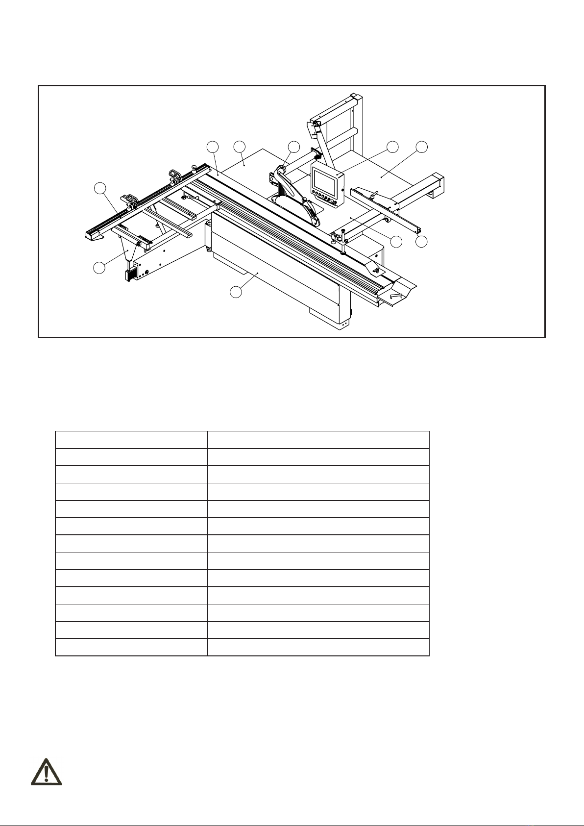
This machine is desinged to make straight and mitre cut for wood material, especially for wood board cutting. CAM
software which can automatically calculate the best layout plan is built in the machine. Also rip fence is controlled by
CNC computer.
Some information and illustrations in this manual may difer from the machine in your possession, since all the
configurations inherent in the machine complete with all the optionals are described and illustrated. Therefore, refer only
to that information strictly connected with the machine configuration you have purchased.
With this manual we would like to provide the necessary information for maintenance and proper use of the machine.
The distribution network is at your service for any technical problem, spare parts or any new requirement you may have
for the development of your activity.
This manual must be read and understood before operating the machine. This will provde a better working knowledge of
the machine, for increased safety and to obtain the best results.
To facilitate its reading, the manual has been divided into sections pointing out the most important operations. For a
quick research of the topics, it is recommended to consult the index. To better stress the importance of some basic
passages, they have been marked by some preceding symbols:
1.2 MACHINE IDENTIFICATION
There is a identification plate fixed to the machine, containing the manufacturer’s data, year of construction, serial
number and technical specifications.
1.3 CUSTOMER SERVICE RECOMMENDATIONS
Apply the machine to skilled and authorized technical staff to carry out any operation dealing with parts disassembly.
Keep to the instructions contained in this manual for the correct use of the machine.
Only skilled and authorized staff shall use and service the machine after reading this manual.
Respect the accident prevention regulations and the general safety and industrial medicine rules.
Indicates imminent risks which may cause serious injury to the operator or other persons. Be
careful and scrupulously follow the instructions.
A statement advising of the need to take care lest serious consequences result in harm to
material items such as the asset or the product.
CAUTION
WARNING
CAUTION
WARNING
2. SAFETY PRECAUTIONS
2.1 SAFETY REGULATIONS
Read carefully the operation and maintenance manual before starting, using, servicing and
carrying out any other operation on the machine.
The manufacturer disclaims all responsibilities for damages to persons or things, which might be caused by any failure
to comply with the safety regulations.
- The machine operator shall have all necessary prerequisites in oder to operate a complex machiery.
- It is prohibited to use the machine when under the influence of alcohol, drugs or medication.
- All the operators must be suitably trained for use, adjustment and operation of the machine.
- The operators must carefully read the manual paying particular attention to the warning and safety notes. Furthermore,
they must be informed on the dangers associated with use of the machine and the precautions to be taken, and must be
instructed to periodically inspect the guards and safety devices.

- Before carrying out adjustment, repair or cleaning work, disconnect the machine from the electric power by setting the
main switch to stop.
- After an initial bedding-in period or many hours of operation, the driving belts may slacken; this causes an increase in
the tool stopping time (the stopping time must be less than 10 seconds). Immediately tighten them.
- The working area around the machine must be kept always clean and clear, in order to have an immediate and easy
access to the switchboard.
- Never insert materials which are different from those which are prescribed for the machine utilization. The material to
be machined must not contain any metal parts.
- Never machine pieces which may be too small or too wide ithrespect to the machine capacity.
- Do not work wood which has evident defects (cracks, knots, metal parts, etc.)
- Never place hands among the moving parts and/or materials.
- Keep hands clear from the tool; feed the piece with the aid of a pusher.
- Keep the tools tidy and far away from those not authorized persons.
- Never employ cracked nor uckled, neither not correctlyreground tools.
- Never use the tools beyond the speed limit recommended bythe producers.
- Carefully clean the rest surfaces of tools and make surethat they find perfectly horizontally positioned, and with no
dents at all.
- Always wear gauntlets when handling the tools.
- Mount the tools in the right machining direction.
- Never start the machine before having correctly installed all the protections.
- Connect the dust suction hoods to an adequate suction system; suction must always be activated when the machine is
switched on.
- Never open doors or protections when the machine or the system is operating.
- Many unpleasant experiences have shown that anybody may wear objects which could cause serious accidents.
Therefore, before starting working, take any bracelet, watch or ring off.
- Button the working garment sleeve well around the wrists.
- Take any garment off which, by hanging out, may get tangled in the MOVING UNITS.
- Always wear strong working footwear, as prescribed by the accident-prevention regulations of all countries.
- Use protection glasses. Use appropriate hearing protection systems (headsets, earplugs, etc.) and dust protection
masks.
- Never let unauthorized people repair, service or operate the machine.
- The manufacturer is not responsible for any damage deriving from arbitrary modifications made to the machine.
- Any transport, assembly and dismantling is to be made only by trained staff, who shall have specific skill for the
specified operation.
- The operator must never leave the machine unattended during operation.
- During any working cycle break, switch the machine off.
-4-

2.2 RESIDUAL RISKS
Despite observance of all the safety regulations, and use according to the rules described in this manual, residual risks
may still be present, among which the most recurring are:
- contact with tool
- contact with moving parts (belts, pulleys, etc..)
- recoil of the piece or part of it
- accidents due to wood splinters or fragments
- tool insert ejection
- electrocution from contact with live parts
- danger due to incorrect tool installation
- inverse tool rotation due to incorrect electrical connection
- danger due to dust inhalation in case of working without vacuum cleaner.
Bear in mind that the use of any machine tool carries risks.
Use the appropriate care and concentration for any type of machining (also the most simple).
The highest safety is in your hands.
2.3 SAFETY AND INFORMATION SIGNALS
This signals may be applied on the machine; in some cases they indicate possible danger conditions, in others they
serve as indication.
Always take the utmost care.
SAFETY SIGNALS:
Risk of eye injury. Wear eye protection.
Wear hearing protection systems.
Danger of electric shock. Do not access the area when the machine is powered.
Carefully read and understand the manual before using the machine.
INFORMATION SIGNALS:
Indicate the technical characteristics, direction of rotation and inclination, block and release, etc.
Carefully following the directions to simply the use and adjustment of the machine.
The signals are graphically described and do not require further explanation.
-5-
- In case of long working cycle breaks, disconnect the general power supply.
- The operating method to be followed in the event of accident or breakdown, the machine should be turned off
immediately and unplug from main power and ask for assistance for the authorized people. If a blockage is likely to occur,
the workpiece should be move back a little and enable the equipment to be safely unblocked.
WARNING
WARNING
WARNING The manufacturer shall not bear any liability for the accidents caused by the failure of the
electrical components of the connected machine and the non-standard installation.
The manufacturer shall not bear any responsibility for changing the mechanical use or altering
the accident caused by parts.
The manufacturer shall not be liable for any accidents caused by the operation of any part or
any part thereof.

3.2 TECHNICAL SPECIFICATION
-6-
1
2
53
8
6
10
7
4
9
Motor voltege 415V/50Hz
Main motor power 7.5HP
Scoring motor power 1HP
Main blade diameter 400mm
Scoring blade diameter 120mm
Main saw blade axis diameter 30mm
Scoring blade axis diameter 20mm
Main blade speed 3000/4000/5000rpm
Scoring blade speed 8000rpm
Blade tilt degree 45°~90°
Sliding table cutting stroke 3800mm
Max cutting thickness 125mm
Max cutting width 1500mm
For avoiding electric shock or fire, maintenance of electric system should be carried out by
professional staffs and using authorized original accessories.
3.3 ELECTRICAL CONNECTION
- Electrical installation should be carried out by competent, qualified personel.
- The mains connection should be made using the terminal box.
- Replacement of the power supply cable should only be done by a qualified electrician
- Connect main leads to a standard 400V ±10% electrical supply which has protection devices of under-voltage, over-
voltage, over-current as well as a residual current device(RCD) which maximum residual current rated at 0.03A.
3. SPECIFICATIONS
3.1 MAIN COMPONENTS
1 - Sliding carriage assembly
2 - Cross cutting fence assembly
3 - Sliding table assembly
4 - Rear extension table
5 - Saw blade guard assembly
6 - CNC Computer
7 - Right extension table
8 - Rip fence assembly
9 - Main working table
10 - Frame Assembly
WARNING

-7-
U1.1
12345678910
1
2
3
4
5
1
2
3
4
5
KT1
KT1
KM2
KM1T
KS1
KM1L KM1T KM1S
KT1
KM1L KM1S KM1T
KT2
KM1L
KT2
KS1 KT3
KT3
KS2
KS1
Q1
SS1
ST1
KM1L
Q2
F2
KM2
KM5 KM6
PB1
PB2 PB3
1
M
1
M
TR1
KM6
M5
M4
KM5
1
M
U3V3 W3
M3
3
3
M
QS1
F3
Q1
NL1L2L3
Q2
KM2
KM1L
KM1T
W2
U2
KM1S
V2
KS1
M2
M
F1
G2
M1
A+ A- B+ B-
AC1 AC2 AC1 AC2
A+ A- B+ B-
457
2 3
10
08
07
U V W CN2 CN1
R S T L1 L2
75V 0V
75V 0V 75V 0V
12
42
51
16
10
17
18
23
43
11
40 21
19
22
20
25
24
52
15
14
41
0
1
24V
13
1L1 1L3
1L2
W1.2
W1.1
V1.1
U1.2
V1.2
Servo motor actuator
Lifting actuator
Tilting actuator
Lifting motor Tilting motor
KS2
control line
coder
02-1
02-1
Connected to
motion controller
1A+ 1A- 1B+1B- 2A+ 2A- 2B+ 2B-
Main circuit diagram

-8-
CN5
12345678910
1
2
3
4
5
1
2
3
4
5
04-7
04-7
0
1
AB
+-
24V
-G1
24V
0V
-N1
24V
0V
0V
24V
04-7
01-6
01-6
03-6
04-1
04-7
04-4
03-2
03-6
04-1
04-2
04-2
04-2
04-2
04-4
04-5
04-6
03-5
03-8
03-6
03-2
03-3
03-7
03-7
03-3
03-4
03-4
CN13 CN12
HOME0 LIM3+ LIM3-HOME1 LIM0+ LIM0- LIM1+ LIM1- LIM2+ LIM2- EXI0
EXI15EXI14EXI13EXI12EXI11EXI10EXI8 EXI9
OVCC OGND
A+
A-
B+
B-
AC1
AC2
-GF2
PUL+
PUL-
DIR+
DIR-
EN+
EN-
A+
A-
B+
B-
AC1
AC2
-GF1
PUL+
PUL-
DIR+
DIR-
EN+
EN-
39221123
39221123
PUL+
PUL-
DIR+
DIR-
EN+
EN+
DIR-
DIR+
PUL-
PUL+
Motion control card
Connected with Seroo actuator
Power
Motor wire
Coder
Actuator for lifting
Motor wire
Coder
Power
Actuator for tilting
Connected with CNC computer
HL1
CN6 CN7 CN1
NEXT
03-9
HOME2 HOME3
Lift
signal Digital signal
Tilting
signal scram Tilting
zero
Lifting
zero
Rip fence
limitation
Lifting
limitation
Tilting
limitation
Rip fence
zero
Stepper motor motion controller

-9-
0V
0V
-S11 -S12 -S13 -S14 -B1 -B2 -B3-S17 -B4 -B5
12345678910
1
2
3
4
5
1
2
3
4
5
02-8
02-9
02-9
02-9
02-10
02-7
02-8
02-8
02-8
01-8
01-8
02-5
02-502-5
Upper limit Next step
Tilting left limit
Tilting right limit
Lower limit Rip fence plus limit
Rip fence minus limit
Lifting zero point
Tilting zero point
Rip fence zero point
Scram
Motion controller signal

-10-
12345678910
1
2
3
4
5
1
2
3
4
5
-S15 -S16 -B1 -B2 -B3
02-5
02-5
02-2
02-2
0V
0V
I5
I4
I5
I4
I6 I6
I7I7
02-6
02-6
02-6
02-6
I3
I2
I1
02-7
02-7
02-7
02-5
02-5
02-5
Lifting button Tilting button
Power
supply
Power
supply
Touch screen
CNC Computer
Digital readout signal
Connected to
movement controller
Manual Photoelectric Computer

-11-
A
B
3.5
Ensure that the suction system guarantees these values at the hood-houth connection point. (3.5)
Suction mouth diameter:
A - Blade guard ...... ø80 mm
B - Body dust suction ...... ø100 mm
Connect the mouths to the suction system with flexible tubes of adequate diameter. Tighten with clamps. The tube must
be positioned in such a way so as not to obstruct the operator during machining.
WARNING Always work with the suction system on. Always start the suction system and the machine at the
same time.
3.5 DUST EXTRACTION
Proper suction eliminates the risks of dust inhalation and
aids better functioning of the machine. The tables list the
minimum air flow and speed values referenced to each
single suction operation.The related pressure drop at the
dust port is 530Pa.
WARNING Please always use the hearing protection systems if the noise level is over 95dB(A).
The noise levels measured are emission levels and not necessarily the safe working level. Although there is a
correlation between the emission levels and the exposure levels, this cannot be used reliably to determine whether or
not further precautions are required. The factors which affect the actual level of operator exposure include the duration
of exposure, the ambient characteristics and other sources of emission, for example, the number of machines and
other adjacent machining. The permitted exposure values may also vary from country to country. Nevertheless, this
information allows the user of the machine to better evaluate the dangers and risks.
Other factors which reduce exposure to noise are:
- correct tool choice
- tool and machine maintenance
- use of hearing protection systems (e.g. headsets, earplugs,...)
3.4 NOISE LEVEL
No load Load
Sound Pressure Level < 80.4dB(A) < 85.7dB(A)
Sound Power Level < 98.1dB(A) < 100.7dB(A)
Associated uncertainty K=4dB
Measurement made in accordance with EN ISO 3746:1995 and EN ISO 11202:1995
Upper hood Lower hood
Air flow 140 cu.m/h 690 cu.m/h
Saw
Minimum air speed 20 m/s

4. INSTALLATION
Assembly need to be done by an experienced and trained person.
-12-
3
2
4
5
6
7
1
4.1 PACKAGE
- The machine is supplied partly assembled. Prior to use, further assembly is required
- When unpacking the machine the following components are included for the initial assembly
- If any parts are missing, do not attempt to assemble the machine; plug the power cord, or turn the switch off until the
missing parts are obtained and properly installed.
4.1
First carton
1- Sliding table assmebly
Second carton
2- Sliding carriage assembly
3- Cross cutting fence assembly
4- CNC computer assembly
5- Frame assembly
6- Eccentric locking assebmly
7- Clamp assembly
2 cartons:
CAUTION

4.2
550mm
1000KGS
AE
B
C
D
Lifting and handing should only be carried out by
skilled personel specially trained to execute this kind of
operations. During loading and unloading, avoid knocks
to prevent damages to persons and things. Make sure
no one is standing under the overhung load and/or within
the bridge crane working range during machine lifting and
handing.
Lifting may be carried out by bridge crane or self-propelled
lift truck. Before starting the manoeuvres, free the machine
of all the parts used for transport or Packaging that have
remained on the machine. Check that the capacity of the
lifting equipment is adequate for the gross weight of the
machine indicated Fig.4.2.
If hoisting is carried out with a lift truck, proceed as
follows:
– adjust the width of the forks A to 550 mm.
– Insert forks A as in the figure in correspondence to name
plates E ensuring that these are wedged against the
back of the rear feet D.
If a bridge crane or a crane is available,proceed as
follows:
– provide two slings B of suitable length and capacity
(Belts
minimum length 4000mm)
– lift the slings and position them as is shown in the
Fig.4.2
– fasten the slings to the bridge crane C having adequate
lifting power.
– move the bridge crane by small steps to allow the slings
B to settle, until optimum stability conditions are reached.
– lift carefully and slowly, without causing the load to
swing, and place the machine in the selected setting.
– remove the protective wax coat from all tables and
unpainted surfaces, using kerosene or its derivative
products. Do not use any solvent, petrol or gas oil, which
might dull the paint or oxidate machine parts.
-13-
4.2 LIFTING AND UNLOADING
WARNING

4.3 INSTALLATION ZONE REQUIRMENTS
A few elements will be disassembled from the machine main structure due to packaging and shipping requirements.
These loose parts should be installed as follows.
Please tighten all bolts and nuts absolutely. Otherwise, may cause machine wobble or serious injury to the operator or
other persons.
-14-
4.3
Fixing to the floor
The machine must be fixed to the floor.
- Use bolt/nut A to level the feet to ensure machine is well
located.
- Put expansion bolts D into ground, use washer/lock
wahser C and hex nut B to fasten the bolts.
AB
C
D
A C B
1
2
3
1
2
3
H
G
F
A
B
C
D
KJI
E
4.4.2 INSTALL BLADE GUARD
Tools required:
- 4mm socket head wrench
- 12mm socket head wrench
- 13-16mm wrench
- Install engineering bracket F to the main body with 4
bolts H and washer G.
- Cross the rotation axis B through washer C, CNC
computer A, engineering bracket F, tightening with washer
C and nut D.
- Then locating the connected cord attached with the CNC
computer to the groove of bracket F with cable buckle
E/I/J. Tighten it with screw K. 4.4.2
4.4.1
- It is prohibited to install the machine in explosive environments.
The installation zone must be selected evaluating the work space required depending on the dimension of the pieces
to be machined,and taking into account that a free space of at least 800 mm must be left around the machine.It is also
necessary to check The floor capacity and its surface, so that the machine base is evenly resting on its four supports.A
power outlet and a chip-suction system connection shall be closeto the selected machine setting and it must be
conveniently lighted (luminous intensity: 500 LUX).
WARNING
4.4 INSTALL OF LOOSE PARTS - INTRODUCTION
Tools required for assembly
- Wrench 16mm
- 6mm socket head wrench
Install rear subsidiary board A to main operating board
with bolt 1 and washer 2.
Install right subsidiary board B to main operating board
with bolt 1 and washer 2.
4.4.1 INSTAII EXTENSION TABLE

-15-
4.4.4
4.4.5
A
B
C
D
F
E
A
C
D
E
F
B
A
B
C
4.4.3
4.4.4 INSTALL SLIDING CARRIAGE TABLE
- Put the sliding carriage table C into the slot of sliding
table A.
- Put the support rod D into the bottom hole of sliding
carriage table C.
- Lock the handle B.
4.4.5 INSTALL CROSS CUTTING FENCE
- Insert pin A into the corner hole of sliding carriage,
mount knob C to the pin and lock it.
- Insert pin B into the slotted hole of middle sliding
carriage, mount knob D to the pin and lock it.
- Fasten locking handle F of sliding carriage.
- Regulate extension of bolt E could adjust angle between
cross cutting fence and saw blade.
4.4.3 INSTALL SLIDING TABLE
Tools required for assembly:
10mm socket head wrehcn
- Put the sliding table onto the frame support surface.
- Lock the sliding table onto the frame using part A,B and
C.

-16-
A
B
A
B
Tools required:
- 5mm socket head wrench
- 16mm fork wrench
- Put the straight edge B on the main table and extension
table to check the flatness.
- Loosen the bolts A to micro-adjust the flatness.
5.2
5. ADJUSTMENT
Handle the tools with protective gloves.
5.1.2
2mm
F
5.1 SCORER ADJUSTMENT
A
B
E
Forbid to adjust nut E after location(5.1.3).
5.1.1
D
C
5.1.3
Using scoring blade when cutting composite board. The
top height of scoring blade should be 2 mm higher than
the operating board. ( 5.1.1)
Tools required:
- 5mm socket head wrench
Please adjust the scoring blade as following(5.1.2):
- Loosen the handwheel A, adjust the scoring blade to the
right height with knob B, then tighten handwheel A.
- Loosen the bolt D 3 rings using 5mm socket head
wrench, then rotating axis C, adjusting the location of the
scoring blade, tighten bolt D at last.(5.1.3)
5.2 EXTENSION TABLE FLATNESS ADJUSTMENT
WARNING
WARNING
WARNING

5.3 RIP FENCE PRECISION ADJUSTMENT
Tools required:
- 5mm socket head wrench
- 8mm socket head wrench
- Check the verticality between table and rip fence. Firstly,
remove 2 locking screws A, then loosen 2 bolts B and 2
bolts E. Secondly, adjust 2 bolts C with 5mm socket head
wrench to get perfect verticality. At last, tighten 2 bolts B
and 2 bolts E, lock 2 screws A.
- Check the parallel between blade and rip fence. Firstly,
remove 2 locking screws F, then loosen 2 bolts B and 2
bolts E, adjust 2 bolts D with 5mm socket head wrench
to get perfect parallelism. At last, tighten 2 bolts B and 2
bolts E, lock 2 screws F.
D
C
E
B
F
A
D
F
A
C
B
E
5.3
5.4
-17-
5.4 M30 ANGLE METER INSTRUCTION MANUAL
- 5 digital tube display, clear and easy to read
- Measuring scope:±180°
- Automatically read the angle for unexpected power outage
- Buttons can be locked, avoiding faulty operation.
- Angle data react quickly
- Initial angle setting(0° )
- Final angle setting(45°)
5.4.1 SPECIFICATIONS/PERFORMANCE
5.4.2 BUTTON INSTRUCTION
5.4.3 DISPLAY INSTRUCTION
Electric performance Mechanical performance
Resolution ratio 0.1°,0.5° Out dimension 74*36*32mm
Measurement range ±180° Cutout size 66*32mm
Current Max.50mA Fixed mode Fixed by screw on back
Power DC:9V~24V;AC:9V~24V Sensor Default wire length 2.5m
Operating temperature 0℃~+50℃Waterproofing grade Data display instrument IP40,sensor IP65
Storage temperature -10℃~+60℃Weight Max.230g
short press:ESC long press:clear the result, long press again will turn back to earlier result
short press:Increase long press:show initial angle, initial angle can be set in menu P06, operate cautiously
short press:Move to next long press:Invalid
short press:Confirm long press:entering into menu
Display content Info. Statement
-179.9~180.0 Display the measured angle
E30 Display item no. when turning on
Err06 Sensor fault:1)sensor damaged:2)sensor wire damaged:3)display function damage
Err Beyond Angle linear correction, calibration failure

-18-
5.4.4 MENU INSTRUCTION
5.4.5 FAST ADJUSTMENT
5.4.6 DIMENSIONS
5.4.7 CAUTIONS
No. Function Description Parameter Default parameter Parameter Description Remarks
P00 Resolution 0.1、0.5 0.1 Angle display resolution Default setting 0.1°
P01 Correction
parameters 0.0001~2.0000 1.0000 Angle correction parameters
Angle liner proportion
adjustment, return ERR if
adjustment fail
P02 Shake to unlock 0,、0.2、0.5、1、20.2
Shake exceed the
default degree, unlock
automatically.
Default setting 0.2°
P03 Lock time 0~9 5
Maintains a constant Angle
for a period of time, lock the
Angle
Default setting 5s
P04 Angle direction 0、10Positive and negative Angle
switching
0: clockwise Angle is positive; 1:
clockwise Angle is negative
P05 Press to lock 0、10Lock CLR、ZERO、END 0:unlock;1:lock
P06 Initial angle 000.0~359.9 0
Initial Angle value,
regardless of the sensor in
which position, long press
ZERO will display the Initial
Angle value
When the initial Angle shows
0, can do any position reset
function. Under the guidance
of manufacturer operation is
recommended.
P07 Final angle 000.0~359.9 45.0
Final Angle value,
regardless of the sensor in
which position, long press
ZERO will display the final
Angle value.
Default final angle is 45
°, especially designed for
woodworking machinery.
P08 Buzzer 0、11Buzz warning every 45°
0:Stop to use;1:start to
use,-135°、-90°、-45°、0°
、45°、90°、135°buzz warning
Internal calibration has been done at factory, if customers have need to do further liner calibration, please following below steps (take
woodworking equipment as an example):
1、Equipment operate to the initial position, long press the ZERO key, the current Angle will be set to 0 °
2、Equipment operate to END position, long press the END key, the current point is set to 45 °
3、Angle linear correction is complete. Adjust the P06, P07 data, can be set to other Angles
Sensor Dimension Meter Dimension
Installation instructions: sensors use M3 screws, meter use back panel thimble.
- When install this product, if the deviation is too big, will influence the use of precision, can’t even use
- Please do not use this product in the environment of corrosion, acid or alkali, direct sunlight, etc., it may cause failure.
- Reading head wire bending radius must be greater than 25 mm
- The installation of this equipment should be at least 0.5 meters from the circuit breaker, relay, motor capacitor, brakes, clutch,
inverter, etc.
- Cables direction must be separate with power lines in order to reduce noise.

5.5 DIGITAL READOUT ADJUSTMENT
Operation of Digital readout cross cutting fence contains parameters setting panel and operating panel. All signals are inputted by 4
buttons on operation panel and displayed on screen by LED built-in.
5.5.1 Overview-Display
The following display icons or segments of the LCD-display are
used in this software version.(5.5.1)
1-Segments for numeric and text display(including signs, decimal
points, fraction display)
2-Symbols for units and display mode
3-Icons for active tool-offsets 1 ... 3
4-Battery-Status Icons
5-REF symbol: unit needs to be referenced
-For different applications the symbol may be changed for the
unit by parameterP02.
-The standardization of the indicator value must be done
manually with the corresponding multiplication factorP08 and the
decimal pointP03.
-In the Inch-mode an additional fraction display is available.
5.5.1
5.5.2
5.5.3.1
5.5.3.2
5.5.3.3
5.5.2 Key overview
The function of the keys in the parameter level is shown on
the button in the dark box on the left below, thefunction at the
operating level is shown in the bright field size.
(5.5.2)
5.5.3 Parameter Level
5.5.3.1 Activate the Parameter Level
- Hold for about 3 seconds/ then press each 1x.
- The parameter level is activated with this key. After about 3
seconds the display shows „P01“for the firstparameter. When the
button is actuated again, the corresponding parameter value is
displayed, which can thenbe changed. With the help of this all
parameters are successfully selected.(5.5.3.1)
5.5.3.2 Election of the Decade
-1x pressed
-With this key the decade will be advanced by a passage from
left to right. The selected, changeable decade isflashing on the
display.(5.5.3.2)
5.5.3.3 Change Value
-1x pressed
-With this key the value in the selected decade is always
increased by 1 (0…9or 0/1)(5.5.3.3)
-19-

-20-
5.5.3.4 Change Sign
- With key the sign can be changed for some parameters.
(Negative sign is only possible if the value is notZERO)(5.5.3.4)
5.5.3.5 Leave Parameter Level
- Press for about 3 seconds in the parameter level
- All parameters will be retentively stored in the internal flash
memory when leaving the parameter level.
(5.5.3.5)
5.5.3.6 Parameter list
5.5.3.4
5.5.3.5
Parameter: Description: Default:
P01: A
System configuration:
A = 0: Counting positively
A = 1: Counting negatively
1
P02: A
Display mode (affect only the display of symbols!)
A = 0: mm-Mode / Display symbol „ mm “
A = 1: Inch-Mode / Display symbol „ Inch “
A = 2: mm-Mode / Display symbol „ m “
A = 3: mm-Mode / Display symbol „ ° “
A = 4: mm-Mode / Display non symbol
0
P03: A Decimal point ( 0 … 4 ) only for mm-Mode 1
P05: ABC
Keylock:
A: Key „Set“ (0= activated / 1= deactivated)
B: Key „Incr/Abs“ (0= activated / 1=deactivated)
C: Key „*“ (0= activated / 1= deactivated)
000
P08: Multiplication factor ( 0,0001 … 9,9999 ) 0.1000
P09: Reference value ( -9999999 … +9999999 ) Factory setting
P10: Offset 1 ( -9999999 … +9999999 ) 0
P11: Offset 2 ( -9999999 … +9999999 ) 0
P12: Offset 3 ( -9999999 … +9999999 ) 0
P13: A
Configuration Offset (0…3)
A = 0: offset cannot be activated
A = 1: offset 1 can be activated
A = 2: offset 1 & 2 can be activated
A = 3: offset 1 & 2 & 3 can be activated
3
P90: (without function) 0
P99: Indicator in the company version x.xx
Table of contents
Other TOUGHCUT Power Tools manuals