Town & Country Fireplaces TC42D User manual

070918-16 Cool Wall TC42 100001060
Visit www.townandcountryfireplaces.com for the most recent version of this manual
TC42D
COOL WALL VENT KIT
INSTALLATION MANUAL

Cool Wall Vent Kit Contents ........................................................3
TC42 Steel Stud Framing Kit ......................................................4
Steel Frame assembly instructions .......................................5
Mounting the Lower Venting Box to Steel Frame .......................6
TC42 Lintel Knock-outs ..............................................................7
Steel Frame & Lower Venting Box Afxed to TC42 ....................8
Building the Lumber Frame ........................................................9
Mounting the Upper Grill ..........................................................10
Installing the Flexible Ducting ..................................................12
Installation of Fireplace Venting ...............................................13
Distribution of Facing Material .................................................14
Venting Near the Ceiling ...........................................................15
Table of Contents
2Cool Wall TC42 070918-16
100001060

The Cool Wall Vent Kit includes:
• The Upper Grill
• The Lower venting box.
• Five Flexible ducts.
• Hardware for installation
3100001060
Cool Wall TC42 070918-16
Cool Wall Vent Kit Contents

5
2
3
8
7
4
6
When assembling the steel
frame for use with the Cool
Wall Vent kit, exclude
pieces #4 & 6.
Framing tabs
Figure 1: TC42D2 Steel frame parts.
Each Kit Contains:
ITEM DESCRIPTION QTY.
1 SCREW, TEKS #8 X 1/2
(NOT SHOWN)
PKG
40
2 SIDE STUD, VERTICAL INNER
53 3/4” L
2
3 SIDE STUD, VERTICAL OUTER
53 3/4” L
2
4 CENTER STUD, VERTICAL
SHORT
2
ITEM DESCRIPTION QTY.
5 STUD, HEADER HORIZONTAL
58 1/4” L
1
6 STUD PLATE, HORIZONTAL 1
7 BASE PLATE 2
8 FRAMING PLATE 4
4Cool Wall TC42 070918-16
100001060
TC42 Steel Stud Framing Kit

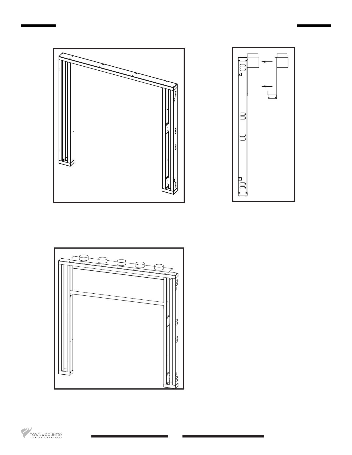
1. Top Frame Assembly
Lay out the horizontal header stud (Item #5 in Figure 1) on a large at surface. (Position all pieces on
their narrow edges as shown in Figure 1.
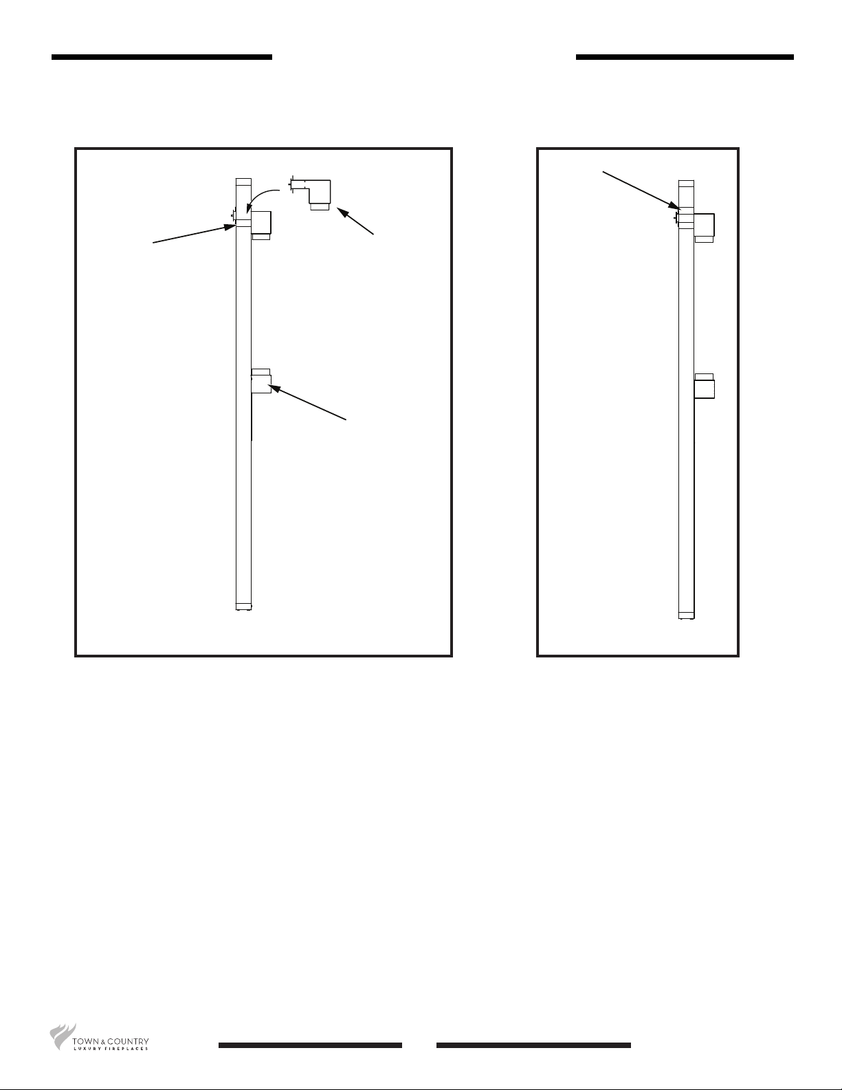
2. Attach Side Studs (Legs)
Lay the inner vertical side studs (Item #2 in Figure 1) so that it’s top end aligns with the 2nd set of
screw holes of the header stud (Item #5 in Figure 1). Fasten with screws provided.
Fasten the vertical outer side studs (Item # 3 in Figure 1) to the ends of the horizontal header stud
(Item #5 in Figure 1).
Position the base plates (Item #7 in Figure 1) at the bottom of the inner and outer side stud legs and
fasten with the screws provided.
Turn the assembled frame over and install screws to the remaining fastening points.
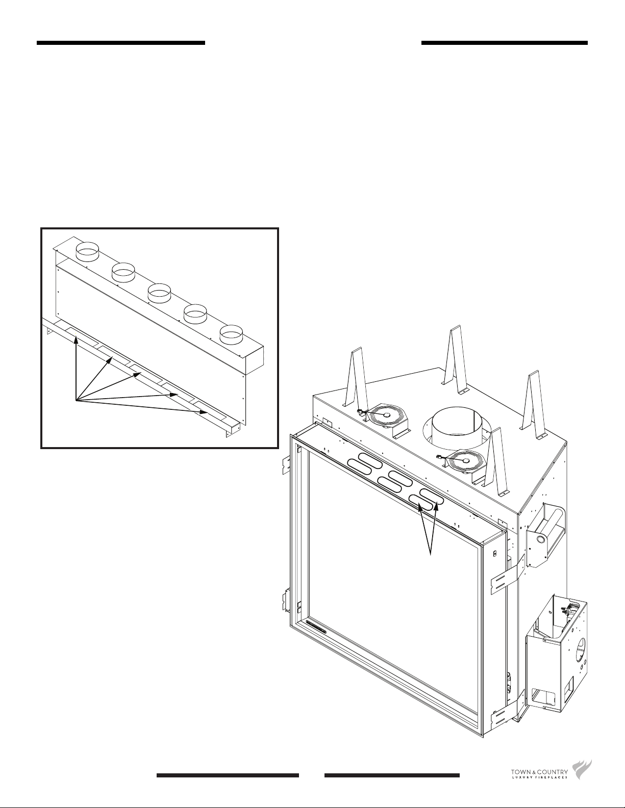
3. Attach Lower Venting Box to steel frame
Align and secure the Lower Venting Box to the steel frame with provided hardware prior to mount-
ing the steel frame and Lower Venting Box onto the TC42. See “Mounting the Lower Venting Box to
Steel Frame” on page 6.
4. Attach the Assembled Frame with the Lower Venting Box to the Unit
Align the assembled frame and Lower Venting Box to the TC42 and attach to the framing brackets
(Items #8 in Figure 1). Align the framing brackets to the fastening points through the access holes in
the outer side studs (Item # 3 in Figure 1).
5. Secure to Lumber Framing using four framing tabs
Bend the (four) framing tabs out and use to secure the steel frame assembly and the TC42 to the
lumber framing through the horizontal top header and the base plates (Items #5 & 7 in Figure 1).
6. Install Facing Material.
Install Facing Material according to the requirements described in “Distribution of Facing Material”
on page 14.
Steel Frame assembly instructions
5100001060
Cool Wall TC42 070918-16

Open cavity to be enclosed
with facing material
Figure 2: Steel frame assembled for the Cool Wall
Vent option.
Figure 3: Lower
venting box aligned to
the steel frame.
Figure 4: Lower venting box attached to the steel
frame.
With the steel frame completed (Figure
2), mount and secure the Lower Venting
Box to the frame (Figure 3) using
supplied hardware.
When the Lower Venting Box is secured
to the steel frame, the front of the
Lower Venting Box will have an open
cavity exposed. This cavity will be
enclosed once the Non-combustible
facing material is installed (Figure 4).
6Cool Wall TC42 070918-16
100001060
Mounting the Lower Venting Box to Steel Frame

Knock-outs (2 rows)
Ports
There are 2 rows of knock-outs (Figure 6) on the TC42 xed Lintel. Only one of these rows will have
their knock-outs removed to accommodate the Lower Venting Box (Figure 5). Which row is removed
depends on where the steel frame is positioned over the TC42 Lintel and the 1/2 inch (minimum)
thickness requirement of the facing material.
If the steel frame is positioned so that the Lintel protrudes from the steel frame to its maximum,
then the rear set of knock-outs will be removed. If the steel frame is positioned so that the Lintel
protrudes minimally from the steel frame, then the front row of knock-outs will be removed.
Note: Be sure of the final placement of the TC42 and its steel frame before deciding on which
row of knock-outs are to be removed.
Figure 5: Lower venting box.
Figure 6: Knock-outs to be removed.
7100001060
Cool Wall TC42 070918-16
TC42 Lintel Knock-outs

Afx the Steel Frame (with the attached Lower Venting Box) to the TC42 using supplied hardware.
Once the steel frame is afxed to the TC42, the entire unit may then be adjusted into its nal
position. The installer must keep in mind that the lumber framing will be built around the steel frame
and the TC42 and so accurate positioning of the unit before construction of the lumber frame is
critical.
Figure 7: Lower venting box and steel frame attached to the TC42.
8Cool Wall TC42 070918-16
100001060
Steel Frame & Lower Venting Box Affixed to TC42

Lower header for upper grill
Steel frame
Conventional lumber frame
Lower venting box
Distance between upper grill &
lower vent depends on length
of flexible ducting. Length of
ducting is from 3 feet min. to 5
1/2 feet maximum.
Figure 8: Building the lumber frame around the steel frame.
Once the TC42 and its attached steel frame is in its nal location, the lumber framing can be built.
A smaller frame must be built into the lumber frame to accommodate the Upper Grill (Figure 8) but
only the bottom horizontal header should be installed at this time.
The Flexible Ducting supplied comes in 3 foot lengths which can be stretched to approximately
5 1/2 feet to allow more distance between the Upper Grill and Lower Venting Box. This allows for
the installation of various sized television sets or other forms of wall hanging. It is necessary when
calculating the nal position of the Upper Grill, to consider where both ends of the Flexible Ducting
will attach to the Upper Grill and Lower Venting Box.
9100001060
Cool Wall TC42 070918-16
Building the Lumber Frame

Bottom header
Lower venting box
secured to steel frame
which is within the
lumber frame
Upper grill
Upper header
Mounting the Upper Grill
When constructing the lumber frame around the steel frame, secure the bottom header for the Upper
Grill to the lumber frame but do not install the upper header (Figure 9). The Upper Grill will t over the
bottom header and can be secured at this time using the supplied hardware.
Once the Upper Grill is secured to the bottom header, the upper header can then be tted over top
of the Upper Grill and secured to the lumber frame (Figure 10).
After the Upper Grill has been installed, the lumber frame can be completed (Figure 11).
Figure 9: Upper grill secured to the bottom header. Figure 10: Upper header
installed to secure the upper
grill to the lumber frame.
10 Cool Wall TC42 070918-16
100001060

Figure 11: Upper grill secured to lumber framing
11 100001060
Cool Wall TC42 070918-16

Installing the Flexible Ducting
Once the Upper Grill is installed, the Flexible Ducting can be installed using supplied hardware.
Figure 12: Flex ducting installed.
12 Cool Wall TC42 070918-16
100001060

Installation of Fireplace Venting
The Fireplace Vent can be installed at this time (Figure 13). It may be necessary to remove the front
stand-offs if they interfere with the routing of the exible ducting.
Figure 13: Side view with replace
venting installed.
13 100001060
Cool Wall TC42 070918-16

Non-combustible facing material
covering the steel frame
Combustible facing material
covering the lumber frame
Distribution of Facing Material
Figure 14: Combustible & non-combustible zones for facing material.
Combustible and non-combustible facing material may now be installed. Refer to Figure 14 for
distribution of facing material. The area above and on either side of the TC42 within the steel frame
must (grey area) use Non-combustible facing material. The area outside of the steel frame may use
Combustible facing material (Dotted area).
It is important to note that all facing material must be a minimum of 1/2 inch thick. The thickness of
the facing material must be calculated into the nal position of the TC42 and its steel frame.
14 Cool Wall TC42 070918-16
100001060

Ceiling
Upper Grill
(May be combustible material)
48”
Do not place
combustible
materials such
as electronics or
artwork below
this point.
Venting Near the Ceiling
If desired, the Upper Venting Box may be placed as close to the ceiling as it is possible (Figure 15).
It is not necessary for the ceiling to be made with non-combustible material. The heat expelled from
the Upper Venting Box is not high enough to damage the ceiling material.
Do not place combustibles such as electronics or artwork within the rst 48” from the oor.
Figure 15: Side view of upper grill near ceiling.
15 100001060
Cool Wall TC42 070918-16

© 2018 Copyright Pacic Energy Fireplace Products LTD
Reproduction, adaptation, or translation
without prior written permission is prohibited,
except as allowed under the copyright laws.
Printed in Canada
For technical support, please contact
your retailer
Web site: www.townandcountryreplaces.com
2975 Allenby Rd., Duncan, BC V9L 6V8
Table of contents
Other Town & Country Fireplaces Fan manuals
Popular Fan manuals by other brands

Vornado
Vornado ATOM 2S AE owner's guide

Valore
Valore LA34 quick start guide

Delta Electronics
Delta Electronics Exhaust Fan FFB Series specification

Heatrae Sadia
Heatrae Sadia HRU ECO 4 user manual

Cata
Cata MT-100 Operation and maintenance instruction

Vent-Axia
Vent-Axia Kinetic Advance White installation instructions

Hunter
Hunter Holden Owner's guide and installation manual

Signature
Signature S116N Your safety & instruction manual

Hunter
Hunter Rockefeller 94041 owner's guide

CLIMAVENETA
CLIMAVENETA HRD2 050 User and installation manual

Fantech
Fantech Ezifit Thru Roof ERV150 installation instructions

NuAire
NuAire MRXBOX-ECO3-1Z installation manual