TOYOTA ADVANCED LOGISTICS Bastian SOLUTIONS BSBAC 1 HP Manual
Installation and Maintenance Manual
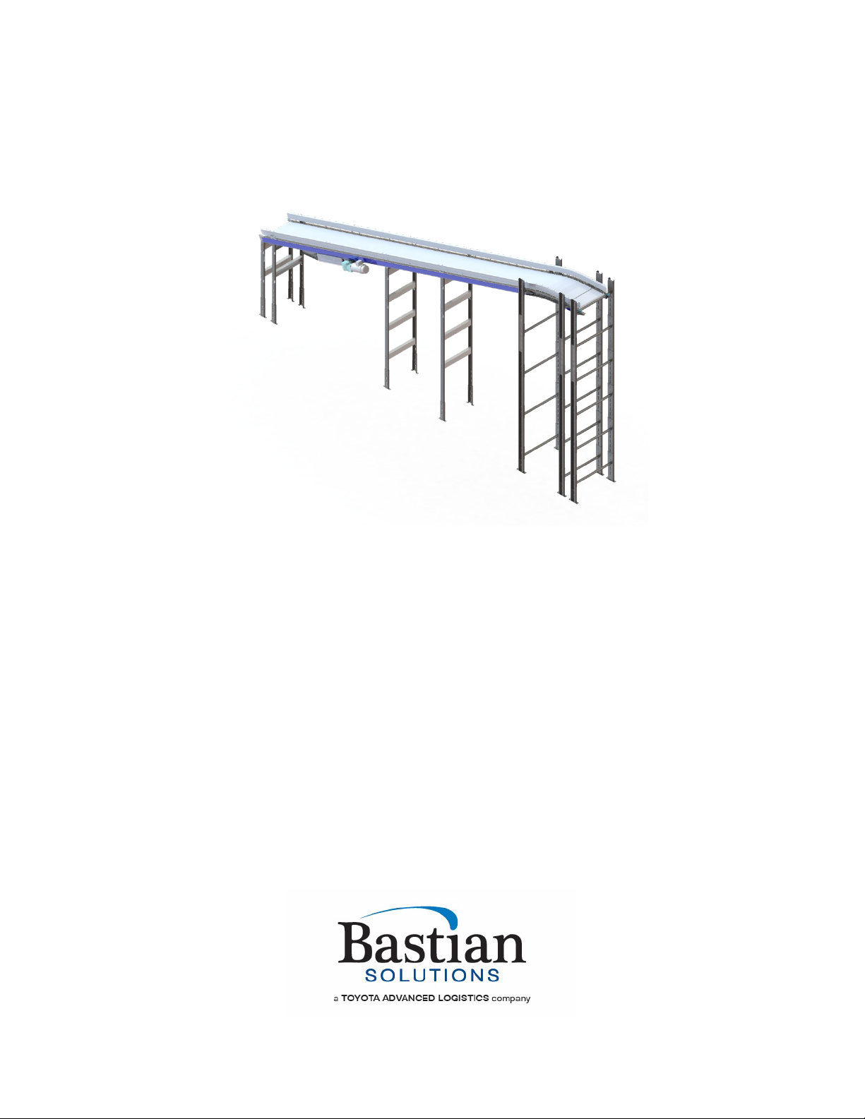
Model: BSBAC 1 HP
Effective January 2022
Rev. B

Installation & Maintenance Manual: BSBAC 1 HP
Published January 2022 Rev. B 2
Contributions
ROLE
NAME
TITLE
Author Rajarshi Choudhuri Design and Cost Engineer
Checker Ben Baker Senior Design Engineer
Approver Chris Perry Engineering Manager
Revision History
DATE
REVISION
REVISION DESCRIPTION
AUTHOR
12/27/2019
A1 Initial document creation Rajarshi Choudhuri
11/3/2021
B Branding and style updates Andrew W. Jones
1/10/2022 Review B MKT final draft Mark Fishback

Installation & Maintenance Manual: BSBAC 1 HP
Published January 2022 Rev. B 3
Term and Acronym Definitions
TERM/ACRONYM
DEFINITION
AC
Alternating current
BF Between frame; this refers to the distance between conveyor bed
side frames.
BHCS Button head cap screw
BOM Bill of Materials
BRBAC
Belt Over Roller Bed Alternating Current; Format of AC conveyor
used for cartons, cases, or totes transport optimized for long runs.
Low friction option for conveying cartons, cases, or totes of various
shapes, sizes, and weights using rollers to support the belt.
BRBACI
Belt Over Roller Bed Alternating Current Incline; Inclined BSBAC.
BSBAC
Belt Over Slider Bed Alternating Current; Format of AC conveyor
used for carton, case, or tote transport optimized for long runs. Low
friction option for conveying carton, case, or tote or various shapes,
sizes, and weights using sheet steel to support the belt.
BSBACI
Belted Slider Bed Alternating Current Incline; Inclined BSBAC
CB Carriage bolt
CCW Counter-clockwise
Center Drive Drive format of AC conveyor where the drive unit is mounted at any
point along the length of the conveyor.
CW
Clockwise
Discharge
The point where cartons, cases, or totes exit a conveyor or similar
unit used in a material handling system.
FAT Factory Acceptance Testing
Flange A feature in sheet metal consisting of a face and bend connected to
an existing face along a straight edge.
Glide Top
An AC belt format with a low coefficient of friction designed to allow
cartons, cases, or totes to slide across the conveying surface.
Guide Rail Mechanism used to maintain the desired position of conveyable
cartons, cases, or totes on their respective conveying surface.
HHCS
Hex head cap screw
ID
Inner diameter of a circular, cylindrical or arced body.
Idler Roller Cylindrically-shaped material handling component that is unpowered
and used to support a belt.
Infeed The point where cartons, cases, or totes enter a conveyor or similar
unit used in a material handling system.
Live
A zone of conveyor runs "live" when it runs whenever energized. It is
for this reason that live zones of conveyor do not have or need any
photoeyes or reflectors.
Longitudinal Rib
A belt format with a rib texture aligned with the belt’s direction of
travel.
LOTO Lockout Tagout

Installation & Maintenance Manual: BSBAC 1 HP
Published January 2022 Rev. B 4
Mark Number
A numeric or alphanumeric term used to uniquely identify a conveyor
bed or collection of beds (of similar model type) within a material
handling system.
Match A mark made on mating conveyor assemblies to assist in identifying
orientation and placement within a system.
Noseover An arced conveyor used to make a smooth transition between
conveying surfaces of differing incline or decline angles.
OAW
Overall width of any given conveyor bed.
OD
Outer diameter of a circular, cylindrical, or arced body.
OSHA
Occupational Safety and Health Administration
Polytier
Heavy duty floor support with a wide stance, capable of supporting
multiple levels and types of conveyor.
Power feeder A section of BLVDC that will always be at the infeed of an inclined AC
or the discharge section of a declined AC.
PPE
Personal protective equipment
Pulley Mechanical device used to change the direction of the belt in a
conveyor system, to drive and/or tension the belt.
Return Idlers Belt-routing rollers on the underside of any given AC conveyor.
Roller
Powered or unpowered cylindrically-shaped material handling
component used for mechanical power transmission, a conveying
surface, and/or support for a belted conveying surface.
Side Cover A PVC cover used to conceal and protect electrical components and
wiring from foreign debris and moving obstacles.
Side Frame
Structural member used to support rotating components needed for
conveyor beds.
Splice Assembly
A five-component assembly-consisting of a plate (or formed plate),
two bolts, and two nuts-that is used to secure a piece of guide rail to
an adjacent piece of guide rail, or a side frame to an adjacent side
frame. This is used to provide additional structural rigidity and ensure
relative position of components is maintained.
Tail Pulley
A non-driven pulley located at the tail end of the conveyor.
Take-up Pulley Pulley with an adjustable position used to eliminate unnecessary
slack in a belt.
Take-up Screws
Adjustment screw used to adjust the position of a take-up pulley.
TOR Top of roller; this refers to the elevation of the conveying surface with
respect to the floor on which the conveyor is sitting.
Track To adjust the position of conveyor components in such a way that
encourages proper belt alignment on a system.

Installation & Maintenance Manual: BSBAC 1 HP
Published January 2022 Rev. B 5
Table of Contents
1Introduction............................................................................................................. 8
2OSHA and Safety .................................................................................................... 8
3Model: BSBAC 1 HP ............................................................................................... 9
3.1 Drive Section ........................................................................................................................10
3.2 Tail Section........................................................................................................................... 12
3.3 Bed Section ..........................................................................................................................13
3.4 Noseover Section ................................................................................................................. 14
3.5 Power Feeder Section ..........................................................................................................15
4Receiving............................................................................................................... 16
4.1 Mark Numbers ......................................................................................................................16
4.2 Skid Contents.......................................................................................................................17
4.3 Skid Documentation.............................................................................................................18
5Installation............................................................................................................. 19
5.1 Floor Support Location........................................................................................................ 19
5.2 Uniform Levelling and Straightness of Conveyor Section ................................................. 20
5.3 Installing the AC Belt ........................................................................................................... 20
5.4 Tensioning and Tracking the AC belt.................................................................................. 23
5.5 Installing and Adjusting Noseover Section Angle.............................................................. 25
5.6 Installing Underside Covers ................................................................................................26
6Maintenance and Operation................................................................................. 28
6.1 Safety During Operation ...................................................................................................... 28
6.2 Mechanical Maintenance Schedule ..................................................................................... 28
6.3 Electrical Maintenance Schedule ........................................................................................ 29
6.4 Tail Pulley Replacement.......................................................................................................29
6.5 Drive Pulley Replacement.................................................................................................... 31
6.6 Take-up Pulley Replacement ............................................................................................... 36
6.7 Snub Roller Replacement .................................................................................................... 39
6.8 Idler Roller Replacement...................................................................................................... 40
6.9 Bearing Replacement and Maintenance.............................................................................. 40
6.10 AC Motor Replacement ........................................................................................................41
6.11 AC Belt Replacement ........................................................................................................... 41
7Troubleshooting and Repair................................................................................ 42
8Spare Parts............................................................................................................ 43
9Appendix 1: Spare Parts - General Arrangements............................................. 44
Table of contents
Other TOYOTA ADVANCED LOGISTICS Industrial Equipment manuals


