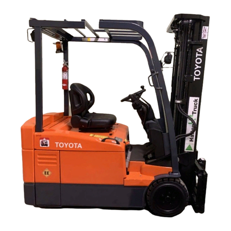
Toyota 7BPUE15 User manual

Serial Numbers
Service
Manual
80,001 and up
7BPUE15


TOYOTA
Service
Manual
High
Level
Orderpicker
Model
7BPUE
1
5
Serial
No.
80,001 and
up
00700-CL222-05,15
March
2005

O
2005
by Toyota Industrial Equipment
All rights reserved. Noportion of this manual may be reproduced mechanically, electronically or by any
other means, including photocop
y
ing, electronic retrieval or transfer, or recording without the written
permission of the publisher.
Toyota Industrial Equipment believes the information in this manual is accurate and current as of the
publication date; such information is subject to change without notice. Toyota Industrial Equipment is not
responsible for any errors that may appear in the manual.


Service Information Bulletins affecting Models
8(7)BRU18-23, 8(7)BDRU15, 7BSU20-25, 6BPU15, 7BPUE15
Service Information Bulletin
1SIB CC06-004 V1.7 Software
2SIB CC05-001R Lift/Lower Without Deadman Brake
(
LLWODM
)
3SIB CC06-003 Home Proximit
y
Switch Relocation
4SIB CE03-003R Solid State Control Handle for Order Pickers
(
6BPU15
)
5SIB CC06-007 Software V1.8 for 7BPUE15
6SIB DF00-001 Wider Pallet Clamp Jaw
7SIB DU05-002 Drive Unit Overhaul / Axle Seal Replacement
(
Reach Trucks
)
8SIB MA04-006 Drive Tire Traction for all 6 & 7 series Reach and Strattle Trucks
9SIB CC00-001 Batter
y
Char
g
e & Lift Interupt Settin
g
s
10 SIB CC01-002 Compatabilit
y
of Firmware & Amplifier Versions
(
Order Picker
)
11 SIB CC02-002 6BPU15 Firmware Update
(
Version 1.6
)
12 SIB CC04-001 Wire Guidance Problems After Displa
y
Card Replacement
13 SIB CC04-002 Steer Oscillation After Calibration
14 SIB CC05-004 Code 9E
(
Order Picker
)
15 SIB CC05-005 Reach Truck Acceleration Settin
g
s
(
7B
(
D
)
RU15-23/7BSU20-25
)
16 SIB CC05-010 7BPUE15 Wire Guidance Set-Up Procedure
17 SIB CE01-004 Improved Horn
18 SIB CE05-003 New Line Driver Assembl
y
(
6BPU15/7BPUE15
)
19 SIB DU01-001 New S
y
nthetic Gear Oil
20 SIB ST06-001 Recommended Special Service Tools
21 SIB CC06-009 STM Board Improvement
22 SIB CC06-11 7BPUE15 Steer Feedback Encoder Chan
g
e
23 SIB CE06-006 Addin
g
Lift Limit with B
y
pass
24 SIB MS06-002 Settin
g
the Mast Back Tilt
25 SIB CC07-001 Password Reference Sheet
26 SIB CC07-002R Tractor Interface Card Improvement
27 SIB CE02-004-R2 Reach Truck Traction Motor Overheatin
g
28 SIB HS07-002 H
y
draulic Filter Gasket Chan
g
e
29 SIB MA07-006 Addin
g
Greaseable Bushin
g
30 SIB CC07-003 Card Pre-Pro
g
rammin
g
(
7BNCU15-25, 7BPUE15
)
31 SIB CE07-003R Reach and Straddle Truck Handle Repair
32 SIB CE07-005 7BPUE15 Extended Foot Pedal Hei
g
ht
33 SIB CC08-007 7BPUE15 Steer Power Head Update
34 SIB ST08-001 Recommended Special Service Tools
35 SIB HS08-003 Pump Motor Brush Improvement
36 SIB CE09-002 Fuse Addition to Over Mast Cable
37 SIB CE09-003 Addin
g
Lift Limit with B
y
pass to 6BPU15
38 SIB DU09-002 Drive Unit Leaka
g
e
39 SIB CC09-002 Software Version 2.2
40 SIB BR09-002 6BPU15 Master C
y
linder Installation
41 SIB CC10-001 Flashware v4.2 for Class II and III Trucks
42 SIB CC10-002 v2.3 Software for 7BPUE15 Orderpicker

Service Information Bulletins affecting Models
8(7)BRU18-23, 8(7)BDRU15, 7BSU20-25, 6BPU15, 7BPUE15
43 SIB HS10-002 Leakin
g
Reach C
y
linder Hose Fittin
g
s
44 SIB BR10-002 Master C
y
linder Chan
g
e
45 SIB MA10-005 AC Motor Temperature Sensor Installation
46 SIB CC11-001 Parameter 22 Explained
47 SIB DU11-001 Orderpicker Drive Unit Overhaul
48 SIB CC11-002 8B
(
D
)
RU15-23 Firmware Update v1.5
49 SIB CC11-003 7BPUE15 Intermittent Codes 18 and 23
50 SIB CC11-005 8B
(
D
)
RU Reach Truck C7 and C9 Confi
g
ure Settin
g
s
51 SIB CE11-006 7BPUE15 Updated Mast Cable Wirin
g
Dia
g
ram
Technical News Brief
1TNB-99-01 - Reach Truck Software Up
g
rade, LPG Re
g
ulator Thermostat
2TNB-03-02 - Reach Truck Handles and Proximity Switch Adjustment for Order Picker and
Reach Trucks
3TNB-07-04 - 7BPUE15 Breakout Cable
4TNB-08-01 Orderpicker Metal Batter
y
Doors
5TNB-2008-15 Holdin
g
Valve for Auxiliar
y
Functions
6 TNB-2008-19 Drive Unit Replacement with 360 Steer
7TNB-2009-02 Reach Truck Steerin
g
Sensitivit
y
8TNB-09-05 How to use the To
y
ota Service Technical Hotline
9TNB-09-06 6BPU15 Master C
y
linder Installation
10 TNB-09-07 8-Series Reach Small Steer Tiller
Hotline Tech Tips
1 HTT-2004-11 - 7BRU backup alarm
2 HTT-2004-12 - Reach Truck backup alarm
3 HTT-2005-03 - 7BNCU Drive Tire Compounds
4 HTT-2005-04 - 6BPU15 Error Code 51
5 HTT-2005-06 - Attachment Installation on 7BPUE, and 7BNCUHouse Valves;
6 HTT-2005-08 - Solid State Handle on the Order Picker
7 HTT-2005-10 - 7BPUE15 Continues Liftin
g
a Few Inches After Releasin
g
the Lift Knob
8 HTT-2005-11 - 6BPU15 brake bleedin
g
9 HTT-2005-12 - Reach and Straddle Truck Caster Ad
j
ustment
10 HTT-2006-02 - 6BPU15 & 7BPUE15 Axle Seal SST’s
11 HTT-2006-03 - Reach truck relief pressure; 6BPU15 code 66 and 67
12 HTT-2006-06 - 6BPU15 Code 66 & 67
13 HTT-2006-07 - 7BPUE15 Addin
g
Side
g
ate Switches
14 HTT-2006-09 - Addin
g
Lift Hei
g
ht Limit to 7BRU Models
15 HTT-2006-11 - 7BRU Mast Set-Up
16 HTT-2006-12 - Travel Speed Measurement without Speedometer
17 HTT-2007-01 - Reach Truck Load Wheels

Service Information Bulletins affecting Models
8(7)BRU18-23, 8(7)BDRU15, 7BSU20-25, 6BPU15, 7BPUE15
18 HTT-2007-02 - Tractor Interface Card Improvements
19 HTT-2007-05 - 7BPUE Breakout Cable
20 HTT-2007-08 - Flashware with Windows Vista
21 HTT-2007-09 - Lift Truck Classifications
22 HTT-2007-10 - Class II BWI li
g
ht
23 HTT-2007-12 - 6BPU15 Wire Guidance
24 HTT-2008-01 - Class II Handle Repair
25 HTT-2008-02 - Flashware Cable for 7BPUE15
26 HTT-2008-03 - Reach Truck Memor
y
Backup Batter
y
Replacement and K1 Rela
y
Volta
g
e
27 HTT-2008-04 - No Updates
28 HTT-2008-05 - Load Wheel Failure on Long Runs, Root Cause Analysis as Part of a
Complete Repair Solution
29 HTT-2008-06 - Troubleshootin
g
Mast Switch Issues on 6BPU15
30 HTT-2008-07 - 7BPUE15 Order Picker Wanders Off Wire
31 HTT-2008-08 - Tips on Testin
g
Wire Harness
32 HTT-2008-09 - Displa
y
Card Replacement and Replacin
g
the Tractor Interface Card on an
33 HTT-2008-10 - 7BPUE15 Service Pendant SST
34 HTT-2008-11 - Class II Drive Unit Replace with 360 De
g
ree Steerin
g
35 HTT-2008-12 - 7BRU, 7BSU, 6BPU, 7BPUE Caster Ad
j
ust, Mast Shimmin
g
36 HTT-2009-01 - Class II Code 65 on Dispal
y
Card Replace
37 HTT-2009-02 - No Information
38 HTT-2009-03 - 8BRU Drive Oil Capacit
y
39 HTT-2009-04 - Class II Gear Case Fill Inspection Plu
g
Location
40 HTT-2009-5 - Class 2 Brake Release Pedal
41 HTT-2009-06 - Class II 6 and 7 Series Reach Truck Memor
y
Backup Batter
y
42 HTT-2009-07 - Class II No Proportional Lowerin
g
43 HTT-2009-08 - 7BNCU Lift Relief Pressure
44 HTT-2009-09 - 7BPUE15 with No Ke
y
-On B+ Volts, Class II "GATE" Code
45 HTT-2009-10 - Class II Wire Guidance - Losin
g
Wire, BWI Li
g
ht Comin
g
On
46 HTT-2009-11 - Class II Drive Unit Leaka
g
e Repair
47 HTT-2009-12 - Troubleshootin
g
Mast Drift Issues
48 HTT-2010-01 - Class II Greasin
g
Caster Wheels
49 HTT-2010-02 - Class I & 11 RF Interference on AC Trucks
50 HTT-2010-03 - Class I & II Flashware v4.2
51 HTT-2010-04 - 7BNCU Diode Replacement, Class II Dispal
y
Mana
g
er Card
52 HTT-2010-05 - No Information
53 HTT-2010-06 - Class II 6BPU15 Master C
y
linder Shimmin
g
54 HTT-2010-07 - 8BR
(
D
)
U Leakin
g
Reach C
y
l. Fittin
g
s
55 HTT-2010-08 - Class II Handle Repair
56 HTT-2010-09 - No Information
57 HTT-2010-10 - Class II 6BPU15 New Brake Master C
y
linder
58 HTT-2010-11 - Class II 7BPUE15 BSOC Tune-abilit
y
,
59 HHT-2010-12 - 8BRU Wirin
g
Dia
g
ram

Service Information Bulletins affecting Models
8(7)BRU18-23, 8(7)BDRU15, 7BSU20-25, 6BPU15, 7BPUE15
60 HHT-2011-01 - Addin
g
Travel Alarm to 8BRU, AC Motor Temp Sensor Installation
61 HHT-2011-02 - Class I-VI Common Electrical Acronyms, Class II Test 61 LPA Software
Version on 24 V 8BRU18
62 HTT-2011-03 - Class II 8BRU Hittin
g
Mechanical Stops when Lowerin
g
63 HTT-2011-04 - Class II Location of Mast Indicator Calibration Wires on 6/7/8BRU Trucks
64 HTT-2011-05 - Class II Addin
g
Hei
g
ht Indicator with Lift Limit to 8BRU
65 HTT-2011-06 - Class II Adding Pressure Transducer, Class I-VI Where to Find Auxiliary
Flow Rate Information
66 HTT-2011-07 - Class II 8B(D)RU Harsh Mast Transition, 8 Series Product Programming the
ETAC Card and Traction Power Amplifier LED Dia
g
nostics
67 HTT-2011-08 - Class II 8B(D)RU15/23 Cooling Fan Air Flow Direction, Back to Basics
Troubleshootin
g
68 HTT-2011-09 - Class II C7 & C9 Confi
g
ure Settin
g
s
69 HTT-2011-10 - Class II 7BPUE15 Dual Mast Cable
70 HTT-2011-11 - Class II 8B
(
D
)
RU Reach C
y
linder Lock Nut Spec
71 HTT-2011-12 - Class II Display Manager Card Replacement, Hyd Oil Maint and Diagnosing
Intermittent Complaints
72 HTT-2012-01 - Class II Display Card Assembly for Reach Trucks, Using DVOM to Check
Volta
g
e Drop

Toyota Orderpicker Model 7BPUE15 Service Manual Table of Contents
Table of Contents
How to Use This Manual
.................................
1
-
1
Map of the Manual
......................................
1
-
2
ManualDesign
.........................................
1
-
4
Page Revision Page
......................................
1
-
5
STARTPage
............................................
1
-
7
Safety
...............................................
2
-
1
Definitions
.............................................
2.2
Generalsafety
..........................................
2
-
3
Battery Safety
..........................................
2
-
6
Staticsafety
...........................................
2
-
9
JackingSafety
.........................................
2
-
11
Tie
-
Down for Transport
..................................
2
-
13
Towing a Disabled Unit
..................................
2
-
14
WeldingSafety
.........................................
2
-
15
Systems Overview
......................................
3
-
1
Vehicle Specification
.....................................
3
-
2
General System Data
.....................................
3
-
5
Installation Instructions
..................................
3
-
7
Wire Guidance
..........................................
3
-
8
Cold Storage
...........................................
3
-
9
UL Label
"
EE
"
.........................................
3
-
11
SpecialTools
..........................................
3
-
12
Planned Maintenance
...................................
4
-
1
Maintenance Guidelines
..................................
4
-
2
Interval 1
..............................................
4
-
3
Interval 2
..............................................
4
-
4
Interval
3
..............................................
4
-
8
Troubleshooting
.......................................
5
-
1
How to Use This Chapter
..................................
5
-
2
Electrical Troubleshooting Guidelines
........................
5
-
3
Shorts to Frame Test
.....................................
5
-
4
TroubleshootingWiring Problems
...........................
5
-
8
Switches (General)
......................................
5
-
10
Electric Motor Tests
.....................................
5
-
11
Battery Discharge Indicator (BDI)
..........................
5
-
13
Contactors
............................................
5
-
15
Fuses
...............................................
5
-
15
Hydraulic Troubleshooting Guidelines
.......................
5
-
16
Definitions
............................................
5
-
17
Electrical Connector Locator Chart
.........................
5
-
18
Programmable Maintenance Tool
...........................
5
-
20
Drive Unit Troubleshooting Guide
..........................
5
-
25
Troubleshooting Flowcharts
...............................
5
-
27
Symptom Tables: Hydraulic Functions
.......................
5
-
31
Symptom Tables: Travel Functions
.........................
5
-
33
Symptom Tables: Electrical Symptoms
......................
5
-
34
Codes and Tests
.......................................
6
-
1
Operator Display Messages
................................
6
-
2
Maintenance Mode
......................................
6
-
4
...
00700.CL222.05,
1
5 March 2005
III

Table of Contents Toyota Orderpicker Model 7BPUE15 Service Manual
........................
Traction PowerAmplifier Fault Codes 6
-
6
.............................
Operator Display Fault Codes 6
-
15
..................................
Component Procedures 7
-
1
..............................
List of Component Procedures 7
-
2
Component Locator Photos
..............................
7
-
5
....................................
Covers and Finish 7
-
11
........................................
Tractor Covers 7
-
11
..................................
Operator Console Cover 7
-
12
...........................................
Mast Guard 7
-
13
Decals
...............................................
7
-
14
..................................
Steeringand Controls 7
-
15
.......................................
Operator Display 7
-
16
........................................
Control Handle 7
-
17
DriveandBrake
......................................
7
-
23
Driveunit
............................................
7
-
24
Drivewheel
...........................................
7
-
25
Brake
...............................................
7
-
27
.................................
Electrical Components 7
-
31
.....................................
Battery Procedures 7
-
32
Motors (General)
.......................................
7
-
35
Drive Motor
...........................................
7
-
39
............................................
Lift Motor 7
-
41
...........................................
Steer Motor 7
-
42
Traction Power Amplifier
.................................
7
-
45
...........................................
Contactors 7
-
46
...............................
Contactor Tip Replacement 7
-
48
Fuses
...............................................
7
-
50
..................................
Circuit Cards (General) 7
-
52
Switches (General)
.....................................
7
-
53
Warning Light
.........................................
7
-
55
Hydraulic Components
.................................
7
-
57
.....................................
Hydraulic Manifold 7
-
58
Hydraulic Reservoir
.....................................
7
-
59
........................................
Hydraulic Fluid 7
-
60
........................................
Solenoid Valves 7
-
61
....................................
Lift Pump and Motor 7
-
62
.......................
Lift Pressure Relief Valve Adjustment 7
-
63
Bleeding the Hydraulic System
............................
7
-
64
.........................................
Side Cylinder 7
-
65
........................................
Center Cylinder 7
-
69
.....................................
Flow Control Valve 7
-
71
Mast Section
........................................
7
-
73
Three
-
Stage Carriage
....................................
7
-
74
InnerMast
...........................................
7
-
78
...........................................
Outer Mast 7
-
81
.....................................
Two
-
Stage Carriage 7
-
82
........................................
Two
-
Stage Mast 7
-
84
.........................................
Mast Bearings 7
-
85
..........................
Mast Disassembly and Shimming 7
-
87
.................................
Lift Chains. Three
-
Stage 7
-
91
Lift Chains. Two
-
Stage
..................................
7
-
93
Forks
...............................................
7
-
94
00700.CL222.05,
1
5 March 2005

Toyota Orderpicker Model 7BPUE15 Service Manual Table of Contents
Pallet Clamp
..........................................
7.95
Loadwheels
..........................................
7
-
96
SkidPads
............................................
7
-
97
Wire Guidance
.........................................
8
-
1
System Overview
........................................
8.2
Install KtComponents
...................................
8.3
Set
-
Up Procedure
.......................................
8.9
CodesandTests
.......................................
8
-
12
Tests
................................................
8
-
35
GeneralTroubleshooting
.................................
8.37
Troubleshooting in Flashware
.............................
8.38
Theory of Operation
.....................................
8.40
Theory of Operation
....................................
9
-
1
Battery Plugged In
.......................................
9.4
Key Switch
(Sl)
On
.....................................
9. 10
Closing Deadman Switches
...............................
9. 16
Travel
...............................................
9
-
22
Steering
..............................................
9.28
Lift/Lower
............................................
9
-
34
Primary Memory
.......................................
9.50
.........................................
PinoutMatrix
9
-
51
Firmware Configuration
.................................
10
-
1
Flashware Program
.....................................
10
-
2
Appendix
.............................................
A-1
Lubrication Specification Chart
.............................
A
-
2
Torque Chart
.
Standard (Ferrous)
...........................
A
-
3
Torque Chart
.
Standard (Brass)
............................
A
-
4
Torque Chart
.
Metric
....................................
A
-
5
Decimal Equivalent Chart
.................................
A
-
6
Standard/Metric Conversions
..............................
A
-
8
ElectricalSchematics
.................................
A
-
11
HydraulicSchematic
..................................
A
-
18
00700.CL222.05,
1
5 March 2005

Table of Contents Toyota Orderpicker Model 7BPUE15 Service Manual
This page intentionally left blank
00700
-
CL222
-
05,
1
5 March 2005

Toyota Orderpicker Model
7BPUE15
Service Manual Section
1.
How to Use
This
Manual
Section
1.
How to Use
This
Manual
00700
-
CL222
-
05,
1
5
March
2005

Section
1
.
How to Use This Manual Toyota Orderpicker Model 7BPUE15 Service Manual
Map
of
the Manual
Map
of
the
Manual
How To Use This
Manual
Safety
rn
Systems
Overview
I
Vehicle Specifications
Planned
Maintenance SpecialTools
Troubleshooting
Codes andTests
rn
Go to Chart
9
Figure
1-1
Table of Contents
r
Map of the Manual
Manual Design
Page Revision Record
00700
-
CL222
-
05,
1
5
March 2005

Toyota Orderpicker Model
7BPUE
15
Service Manual Section
1.
How to Use
This
Manual
Map of the Manual
Component
Procedures
Wire Guidance
Q
Theory of
Operation
Software
Configuration
AlphabeticalList of
Component
Procedures
Component Location
Photos
Component
Procedures by Lift
Truck Systern
Appendix
I
!
Lubrication
SpecificationChart
Torque Charts
Decimal Equivalent
Chart
~
Standard/Metric
Conversions
Electricaland
Hydraulic
Schematics
00700
-
CL222
-
05,
1
5
March
2005

Section
1
.
How to Use This Manual Toyota Orderpicker Model 7BPUE15 Service Manual
Manual Design
Manual Design
This Service Manual is designed with the
following objectives in mind:
Provide technical coverage for expected
levels of user expertise.
Anticipate your needs and reduce your
decisions regarding maintenance.
Reduce page flipping through a
"
one
-
stop
shopping
"
approach.
The two
-
line running page header atthe top of
each page tells you:
Name of the manual
(OrderpickerModel
7BPUE15
Service
Manual)
Current Chapter Title
(e.g.,this page How to Use
This
Manual)
Current topic
(e.g.,this page Manual Design)
We suggest turning to the
START
page first
when you use this manual.
The
START
page asks a few simple questions to
guide you to the proper chapter.
How to Use This Manual
explains the
manual format and design and contains
theTable of Contents and START page.
Safety
explains warning and caution
notes,general safety rulesand safety rules
for batteries, static, jacking, and welding.
Systems Overview
includes truck
dimensions and specifications.
Planned Maintenance
outlines the
recommended schedule of preventive
services to keep your truck working most
efficiently.
Troubleshooting
isa setof
"
decision
-
tree
"
charts designed to take you from a
symptom to a specific sequence of tests in
order to isolate a failing component.
The
START TROUBLESHOOTING
chart (onPage 5
-
27)will guide you to
the individual troubleshooting
symptom chart you need.
Once you're familiar with thesymptoms
listed, you may instead simply find the
symptom chart from the
Troubleshooting Flowcharts
(Page5
-
27).
When you complete a troubleshooting
procedure,be sure to follow the steps in
End of TroubleshootingChart END
-
1
(Page5
-
28).
Codes and Tests
lists the electrical fault
codes and procedures for running
firmware electrical tests.
Component Procedures
gives
step
-
by
-
step procedures for testing,
removal, installation, and adjustment of
individual truckcomponents. Components
aregrouped by truck system.
To find a component procedure, you may
use one of three methods:
Look upthe component name in the
List of
Component Procedures
(Page
7
-
1).
Find the componentin the
Component
Locator Photos
(Page 7
-
5).
Look upthe component name in the
Service Manual
Index
(Page
I
-
1).
Theory of Operations
explains signal flow
within hydraulic and electrical schematics
for various conditions of truck operation.
Appendix
contains reference information
such astorque values, lubrication
specifications, and system schematics.
Index
lists subjects alphabetically.
00700
-
CL222
-
05,
1
5
March 2005

Toyota Orderpicker Model 7BPUE
15
Service Manual Section
1.
How to Use
This
Manual
Page Revision Page
Page Revision Page
This section is a record of all revised pages in
this manual. Whenever a page is revised, this
section is updated and included in the revision
package. this lets you keep track of the latest
revised pages for this manual.
Original Issue
-
No Changes
00700
-
CL222
-
05,
1
5
March
2005

Section
1
.
How to Use This Manual Toyota Orderpicker Model 7BPUE15 Service Manual
Page Revision Page
This page intentionally left blank
00700
-
CL222
-
05,
1
5
March 2005

Toyota Orderpicker Model
7BPUE
15
Service Manual Section
1.
How to Use
This
Manual
START
Page
START
Page
(
START
precautions?
To examine
specifications?
To do scheduled
maintenance?
a problem?
Yes4
Go to Section
2
"
Safety
Go to Section
3
Yes
"
Systems Overview
"
Yes
Yes
1
Go to Chart
1
Figure
1-2.
00700
-
CL222
-
05,
1
5
March
2005
Go to Section
4
"
Planned Maintenance
"
Go to Section
5
"
Troubleshooting
"
Troubleshooting Guidelines
\
TroubleshootingCharts
Table of contents
Other Toyota Lifting System manuals