ClimbTech BTA012N Guide

OPERATION AND INSTRUCTION MANUAL
5,000-lbf (22kN) Beam Trolley: BTA012N
ANSI Z359.1-2007 / OSHA 1910.66 & 1926.502
/ EN 795:1996 (+A1:2000) Class B
V1.3
IMPORTANT!!!
ALL PERSONS USING THIS EQUIPMENT MUST READ AND UNDERSTAND ALL INSTRUCTIONS.
FAILURE TO DO SO MAY RESULT IN SERIOUS INJURY OR DEATH. USERS SHOULD BE FAMILIAR
WITH PERTINENT REGULATIONS GOVERNING THIS EQUIPMENT. ALL INDIVIDUALS WHO USE
THIS PRODUCT MUST BE PROPERLY INSTRUCTED ON HOW TO USE THIS DEVICE.
Read This Instruction Manual Carefully Before Using This Equipment.
User Instructions must always be available to the user and are not to be removed except by the user of this equipment. For proper use, see
supervisor, User Instructions, or contact the manufacturer.
Compliant fall protection and emergency rescue systems help prevent serious injury during fall arrest. Users and purchasers of this
equipment must read and understand the User Instructions provided for correct use and care of this product. All users of this equipment
must understand the instructions, operation, limitations and consequences of improper use of this equipment and be properly trained
prior to use per OSHA 29 CFR 1910.66 and 1926.503 or applicable local standards. Misuse or failure to follow warnings and instructions
may result in serious personal injury or death.
Purpose
The
BTA
012
N
is an anchorage connector designed to function as an interface between the anchorage and a fall protection, work positioning,
rope access, or rescue system for the purpose of coupling the system to the anchorage. Any references to “anchorage connector” in this
manual include, and apply to, the The
BTA
012
N
.
Use Instructions
1. Before using a personal fall arrest system, user must be trained in accordance with the requirements of OSHA 29 CFR
1910.66 in the safe use of the system and its components.
2. Use only with ANSI/OSHA compliant personal fall arrest or restraint systems. The anchorage must have the strength capable
of supporting a static load, applied in the directions permitted by the system, of at least 5,000-lbf (22.2 kN) in the absence of
certication.
3. Use of this product must be approved by an Engineer or other qualied person to be compatible with any and all structural
& operational characteristics of the selected installation location and system to be connected to this anchor. Improper use
may result in serious personal injury or death.
4. The anchorage connector must be inspected prior to each use for wear, damage, and other deterioration. If defective
components are found the anchor connector must be immediately removed from service, in accordance with the
requirements of OSHA 29 CFR 1910.66 and 1926.502.
5. The complete fall protection system must be planned (including all components, calculating fall clearance, and swing fall)
before using.
6. A rescue plan, and the means at hand to implement it, must be in place that provides the prompt rescue of users in the
event of a fall, or assures that users are able to rescue themselves.
7. After a fall occurs, anchorage connector must be removed from service and destroyed immediately.
Use Limitations
1. The
anchorage connector
is designed for a single user, with a capacity up to 310 lbs (140 kg) user including clothing, tools,
etc.
2. The
anchorage connector
may be pulled in any direction shown in the LOADING CONDITIONS DIAGRAM.
3.
The Anchorage connector
is designed to be used in temperatures ranging from -40ºF to +130ºF (-40°C to +54°C).
4. Do not expose the
anchorage connector
to chemicals or harsh solutions which may have a harmful eect.
5. Do not alter or modify this product in anyway.
6. Caution must be taken when using any component of a fall protection, work positioning, rope access, or rescue system near
moving machinery, electrical hazards, sharp edges, or abrasive surfaces, as contact may cause equipment failure, personal
injury, or death.
7. Do not use/install equipment without proper training by a“competent person” as defined by OSHA 29 CFR 1926.32(f).
8. Do not remove the labeling from this product.
9. Additional requirements and limitations may apply depending on anchorage type and fastening option utilized for
installation. All placements must be approved by an engineer or other qualied person. Improper use may result in serious
personal injury or death.
COMPATIBILITY LIMITATIONS
All anchor connectors must only be coupled to compatible connectors. OSHA 29 CFR 1926.502 prohibits snaphooks from being engaged
to certain objects unless two requirements are met: it must be a locking type snaphook, and it must be “designed for” making such a
connection. “Designed for” means that the manufacturer of the snaphook specifically designed the snaphook to be used to connect to the
equipment listed. The following connections must be avoided, because they can result in rollout* when a nonlocking snaphook is used:
• Direct connection of a snaphook to horizontal lifeline.
• Two (or more) snaphooks connected to one D-ring.
• Two snaphooks connected to each other.
• A snaphook connected back on its integral lanyard.
• A snaphook connected to a webbing loop or webbing lanyard.
• Improper dimensions of the D-ring, rebar, or other connection point in relation to the snaphook dimensions that would allow the
snaphook keeper to be depressed by a turning motion of the snaphook.
*Rollout: A process by which a snaphook or carabiner unintentionally disengages from another connector or object to which it is coupled.
(ANSI Z359.1-2007)
MAINTAINANCE, CLEANING AND STORAGE
Cleaning periodically will prolong the life and proper functioning of the product. The frequency of cleaning should be determined by
inspection and by severity of the environment. Clean with compressed air and/or a sti brush using plain water or a mild soap and water
solution. Do not use any corrosive chemicals that could damage the product. Wipe all surfaces with a clean dry cloth and hang to dry, or use
compressed air. When not in use, store anchorage connectors in a cool, dry, clean environment, out of direct sunlight and free of corrosive or
other degrading elements.
WARNING
ClimbTech, LLC. / 7303 Burleson Rd. Suite 901 Austin, TX 78744 / 1(888)206-1318 / www.climbtech.com
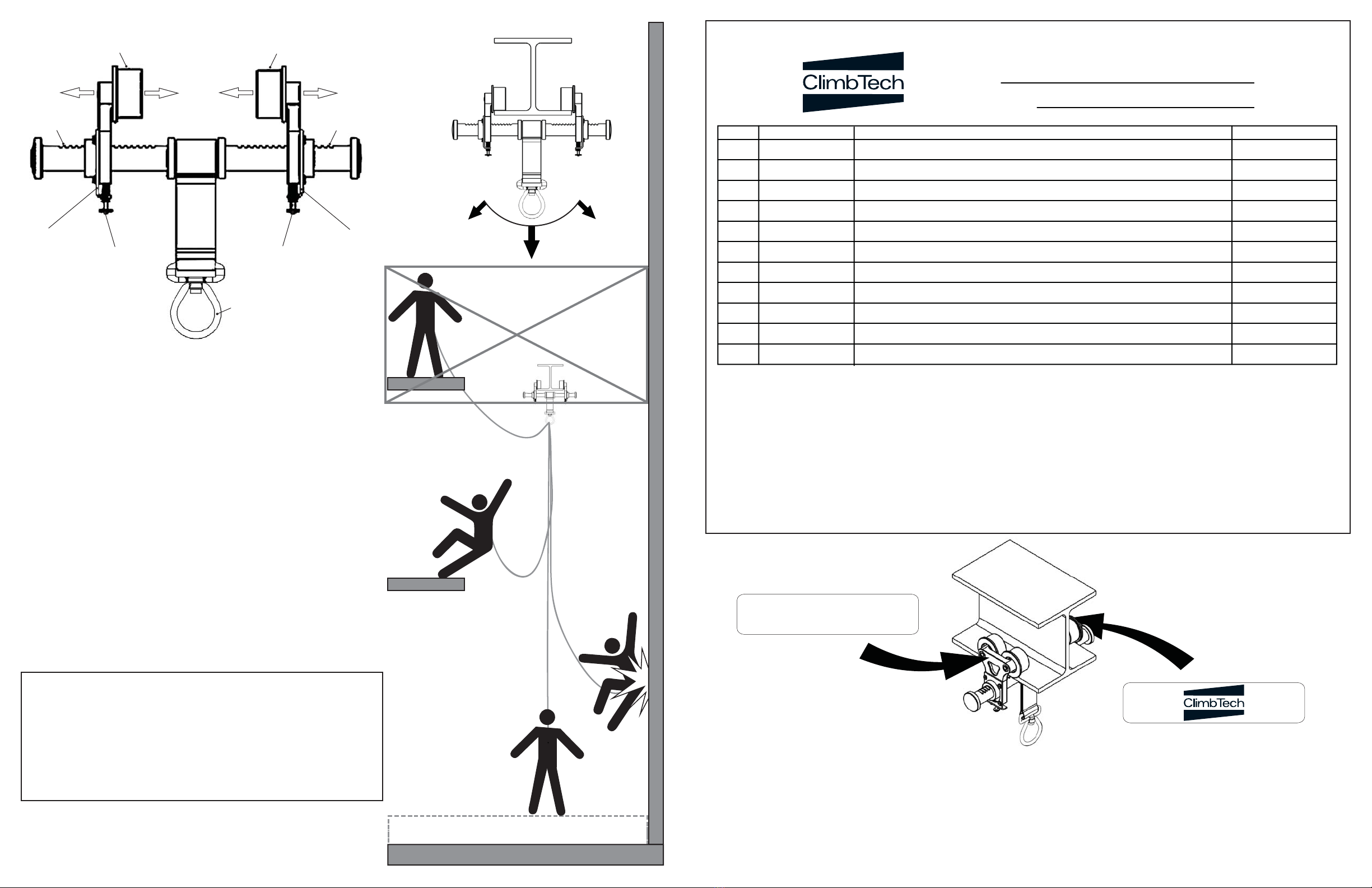
(adjustable directions)
Max 10” or 255mm
Min 3” or 76mm
(Toggle Plate)
(Secondary saftey lock)
(notches) (notches)
(Toggle Plate)
(Secondary saftey lock)
(rollers)
(rollers)
30° MAX
ACCEPTABLE LOADING
DECK/FLOOR/GROUND LEVEL
WORK SURFACE
WORK SURFACE
* DO NOT WORK *
ABOVE ANCHOR POINT
MINIMUM CLEARANCE 3ft (1m)
WARNING!!! SWING FALLS CAN OCCUR WHEN THE WORKIER IS NOT DIRECTLY UNDER ANCHOR POINT.
Product Warranty, Limited Remedy and Limitation of Liability
WARRANTY: THE FOLLOWING IS MADE IN LIEU OF ALL WARRANTIES OR CONDITIONS, EXPRESS OR IMPLIED, INCLUDING THE IMPLIED WARRANTIES OR CONDITIONS
OF MERCHANTABILITY OR FITNESS FOR A PARTICULAR PURPOSE. Equipment oered by ClimbTech is warranted against factory defects in workmanship and materials for
a period of 5 year life cycle from date purchase or rst use by the original owner.
LIMITED REMEDY: Upon notice in writing, ClimbTech will repair or replace all defective items at ClimbTech’s sole discretion. ClimbTech reserves the right to require that the
defective item be returned to its plant for inspection before determining the appropriate course action. Warranty does not cover equipment damage resulting from wear,
abuse, damage in transit, failure to maintain the product or other damage beyond the control of ClimbTech. ClimbTech shall be the sole judge of product condition and
warranty options. This warranty applies only to original purchaser and is the only warranty applicable to this product. Please contact ClimbTech technical service department
for assistance.
LIMITATION OF LIABILITY: IN NO EVENT WILL CLIMBTECH BE LIABLE FOR ANY INDIRECT, INCIDENTAL, SPECIAL OR CONSEQUENTIAL DAMAGES INCLUDING, BUT
NOT LIMITED TO LOSS OF PROFITS, IN ANY WAY RELATED TO THE PRODUCTS REGARDLESS OF THE LEGAL THEORY ASSERTED.
Inspection:
Ocial periodic inspection must be made at least annually. The inspection must be performed by a qualied person other than the
intended user. If severe weather or conditions exist then inspections must be carried out more frequently.
1. Inspect beam anchor to make sure the rollers ride ush with mounting surface and roll smoothly.
2. Make sure all labeling is axed to the unit.
3. Inspect anchoring system for signs of damage or wear.
4. Make sure the unit can adjust and lock properly on to beam ange.
5. Record inspection results in the space provide above.
*If any damage that could aect the strength or operation or unsafe conditions are found proper disposal is required. The
anchorage connector must be rendered unusable and then properly discarded.
INSPECTION AND MAINTAINANCE LOG
MODEL NUMBER:
DATE OF MANUFACTURE:
Part Number Comments Inspector Name
Date
Installation:
1. Locate a structural steel beam ange capable of withstanding a 5,000-lb.
Static load or meeting OSHA 1926.502 requirements for a safety factor of
two. (Max beam ange thickness of 7/8” or 23mm) Mounting location must
be approved by a Engineer or qualied person.
2. Push up on the toggle plate to allow the adjustable rollers to move.
3. Fit the rollers over the edges of the beam ange, keeping the unit perpen-
dicular to the beam.
4. Slide the adjustable rollers so that both sets of rollers are full resting on
the beam ange.
5. Release the toggle plate and pull back on the adjustable rollers to ensure
the ratchet teeth are fully seated in the nearest ratchet notches.
6. Tug, rock, and twist the anchor in all directions to ensure that it cannot
come o of the ange.
7. Screw tight the secondary saftey locking screws on the bottom of the
toggle plate to insure the rollers can not move o the edge of the ange.
8. The rollers must ride on a clear surface. Remove any dirt and grit if nessary.
9. Ensure that Beam Trolley can not slide o the end of the beam it is
attached too. Install stoppers if necessary.
*Always re-adjust according to steps 1-9 above when moving to a new
or dierent size beam.
Performance:
Static tensile strength: 5000-lbf
(22kN) minimum.
Maximum capacity: one worker with
max weight of 310-lbs when used as a
single point anchorage connector for
personal fall arrest or restraint system.
Dimensions:
Weight: 7.7-lbs
Beam ange width range: 3”-10”
Beam ange thickness: Up to 7/8”
Regulatory compliance:
OSHA 1910.66 & 1926.502 ANSI
Z359.1-2007, Z359.7-2011 / EN 795:1996
Component Materials:
Aluminum: cross bar, rollers, Polyester: webbing, Zinc Plated Steel: swivel,
Stainless Steel: spring, hardware
*All products subjected to fall arresting forces should be
removed from service immediately!
USE AND INSTALLATION INSTRUCTIONS
BEAM TROLLEY
Aluminum, Zinc Plated Steel,
Stainless Steel
(1) person 310-lbs
Model: BTA012N
1-(888)-206-1318
Lot: xxx MFG: mm/yyyy
(ANCHOR POINT)
30° MAX
(5,000-lbf Swivel)
V1.3
WARNING: All persons using this equipment must read,
understand and follow all instructions. Failure to do so may
result in serious injury or death. (INSPECT BEFORE USE)
COMPLIANCE:OSHA 1910.66 & 1926.502 ANSI Z359.1-2007
Z359.7-2011 CE 0321 / EN 795:1996 (+A1:2000) Class B


