TPC ERN C Series User manual

COIL WINDING MACHINE ERN C-VERSION
USER´SGUIDE
ERN 22,32,32S,42,52
TPC s.r.o
Pálenica 53/79
03301 Liptovský Hrádok
SLOVAKIA
Tel.: +421-44-5221366
Fax: +421-44-5222088
www.tpc.sk

1. Introduction
1.1 Characteristic features
2. Technical data
2.1 Climatic conditions
3. Description of machine
3.1 Description of controls
4. Installation and preparation of working equipment
4.1 Connection to the power
5. Winding operation
5.1 Machine switching ON and gear setting
5.2 Winding data back up while electricity drop
5.3 Winding and view window
5.4 Explanation of conceptions STANDSTILL, START, STOP
5.5 Winding program selection
5.6 Start and Stop of winding cycle
5.7 Foot pedal
5.8 Protection shield
5.9 Winding corrections
5.9.1 Spindle reference position setting
5.9.2 Wire guide relative position setting
5.9.3 Number of turns correction
5.9.4 Total counter
5.9.5 Wire guide correction
5.9.6 Wire guide direction change
5.9.7 Step abort
5.9.8 Back winding
5.9.9 Deceleration ramp for the STOP - button
6. Programming
6.1 Basis of programming
6.2 Step choice
6.3 Step parameters programming
6.3.1 Basic step types
6.3.2 Choice of step type
6.3.3 Winding step
6.3.4 Wire guide shift
6.3.5 Wire guide jump
6.3.6 Pause
6.4 Display and assignment of the layer
6.5 Programming corrections
6.5.1 Empty step insert
6.5.2 Step cancel
6.5.3 Step copy
6.5.4 Global change
6.5.5 Coordinate offset
6.6 Special functions
6.6.1 Layer-stop
6.6.2 Automatic correction
6.6.3 Automatic switch to manual regime
6.6.4 Trapezoidal winding
1
1
2
2
2
3
6
6
7
7
9
10
10
11
12
12
13
14
14
14
15
16
17
17
18
18
19
20
21
21
22
22
22
23
28
30
31
33
34
34
35
36
37
38
39
39
40
42
43

6.7 Auxiliary inputs and outputs
6.7.1 View window for inputs and outputs
6.7.2 Digital inputs programming
6.7.3 Digital outputs programming
6.7.4 Analog output
7. Program saving and opening
7.1 Program opening
7.2 Program saving
7.3 Program copy
8. Menu
8.1 Program locking
8.2 Error messages
8.3 Machine model choice
8.4 Display language
8.5 Joystick action
8.6 Winder number
8.7 Access PIN code setting
8.8 Displaying of layer
8.9 Winder version choice
8.10 Counter clearing mode
9. ERROR report
10. Application programme closing (Color_Disp)
11. Firmware upgrades
11.1Upgrade of the application programme Color_Disp
11.2Upgrade of the control board / keyboard
12. Creation and modification of the operator list
13. Production log settings and terminal mode
13.1Production log
13.2Terminal mode
14. New devices drivers and hibernation
15. Network connection
16. Gear change
17. Serial interface RS 232
18. Package contents
19. Fuse change
20. Maintenance
21. Warranty period and service
22. Appendices
45
45
46
47
49
51
52
53
54
55
57
57
58
59
59
60
60
61
61
61
62
63
64
64
64
65
66
66
67
69
70
72
72
73
73
73
73

1. INTRODUCTION
Bench-type universal coil winding machine ERN is designed for winding the coils,
transformers, chokes, resistors etc with wire up to - see technical data.
1.1 Characteristic features:
- wide range of application for winding simple or complicated coils, multichamber coils,
trapezoidal or asymetric windings
- AC servo, that is used like a spindle drive assure excellent dynamical parameters,
constant torque and accure positioning
- wire guide on ball bearings with a separate stepping motor
- accurate reversible turn counting
- microprocessor-controlled winding cycle without time waste
- wide programming options
- memory 2 Gb (by the CF card capacity), each program up to 350 steps
- viewable and easy reading graphical display
- special functions LAYER-STOP, AUTOMATIC CORRECTION, MANUAL REGIME
- 4 programmable digital outputs
- 4 programmable digital inputs
- 1 programmable analog output
- communication with PC by optically isolated interface RS-232 and USB host port
- possibility for the creation of a wireless network by LAN or BLUETOOTH modules
1 / ERN C

2. TECHNICAL DATA
Wire diameter (mm):
Pitch range (mm/rev):
Winding width (mm):
Winding speed / torque (rpm/Nm):
Accuracy of spindle stop (rev):
Spindle position pre-set (rev):
Max.speed of wire guide - shift (mm/s)
- winding
Acceleration/deceleration:
Max.coil diameter (mm):
Distance between centres (mm):
Dimensions (mm):
Weight (kg):
Power supply (V/Hz):
Power consumption (kVA):
Noise (dB):
3. DESCRIPTION OF MACHINE
Coil winding machine ERN consists of the following parts:
- controller containing control electronics and programming elements
- drive unit containing servomotor with gears, pitch control unit with stepping motor,
power electronics and control elements
- base plate
- protection shield
- support with spool holders and dereelers (optional accessories)
- tailstock (optional accessories)
- wire guides (optional accessories)
Winding cycle (linear acceleration, max.speed, linear deceleration and stop) is running automaticly
after pressing the START-button. Deceleration is controlled by microprocessor to ensure
accurate stopping and spindle positioning.
rpm MAX.SPEED
NUMBER OF TURNS
C LE AT ONDE E R I
LI EA ACC LER.N RE
2.1 Climatic conditions
Machine is designed for normal workshop´s conditions with relativ air moisture
70% and temperature in the range +15 up to +30 C.
ERN22
0,02 - 1,7
0,008 - 40
0,1 - 210
12000 / 0,7
6000 / 1,5
3000 / 3
0,01
0,01
100
75
table
180
250
780 x 420
85
230 / 50-60
1
74
ERN32
0,02 - 2,5
0,008 - 40
0,1 - 300
6000 / 1,5
1500 / 6
750 / 12
0,01
0,01
100
75
table
250
340
870 x 460
120
230 / 50-60
1,2
74
ERN32S
0,02 - 3,0
0,008 - 40
0,1 - 300
4000 / 3
1000 / 12
500 / 24
0,01
0,01
100
75
table
250
340
870 x 460
120
3x 400/50-60
1,5
74
ERN42
0,02 - 5,0
0,008 - 40
0,1 - 300
4000 / 3,5
1000 / 15
500 / 30
0,01
0,01
100
75
table
450
330
910 x 530
140
3x 400/50-60
1,5
74
ERN52
0,02 - 5,0
0,008 - 40
0,1 - 450
4000 / 3,5
1000 / 15
500 / 30
0,01
0,01
100
75
table
450
650
1235 x 530
180
3x 400/50-60
1,5
74
2 / ERN C

3.1 Description of controls
1 - POWER ON / OFF switch
2 - EMERGENCY STOP - disconnects power in emergency
3 - POWER ON indicator
4 - START button - starts winding cycle
5 - STOP button - interupts winding cycle
6 - BRAKE ON / OFF - switches on/off the electromagnetic brake
7 - DISPLAY
8 - ENTER button - enters data to the memory
9 - PLUS and MINUS buttons - parameters correction and step choice
10 - RESET - sets the initial state
11 - Numeric buttons - enter the coil name as well
12 - Multifunction buttons - display served options choice
13 - Function buttons
14 - Connector for serial interface RS 232
15 - Gear cover with timing belt
16 - Connector for foot pedal
17 - Fixing screws
18 - Connectors for inputs and outputs
19 - Power plug
20 - AC circuit breaker
21 - USB host port
3 / ERN C

4 / ERN C
I
0
EMERGE CY STON P
KBRA E
POWER
19
6
3
15
14
17
16
18
2 1 45
PYTO
EFPSCE/
O
IU
NT
TOARB
SP
E
T
PD
SE
E
PD
S E
L
I
N
ET
SPCUI
FO TN N
L C C YE
CIT
P HPY
O
TE F C K
BO LN M EUID
IR G
WEE
U
N
PSI
O
IO
T
II R D GWEE U
TDN
IRCI EO
EA
P L
D
OIP NTO
P INT
FE
E.
LR
TV.H RR T V
I G ER C R O
T g
hc
os
C
en y
P o n
dt
ry
coo m
p
u
l a
t
e:
2
Sp
:0
y
rLa
e
io 05
s
P6
oit n :1.
tp
:D
e I G
NxsI
eNNt W
oF
K
21
Nt Ci3 0
o
e: l 2
G
I
WNDIN
TSP
O
310.
53
T
NE CORR
X.
()
2
WIRE GUIDE
DROI EI
CT N
WRIE U
D
GIE
SOT I
P O N
I
112233
445566
00
778899
C
C
. .
-
-
+
+
20
2
1
ON R
CTROLLE
C
ERN -
ON R
CTROLLE
C
ERN -

21
7
13
12
11
10
8
9
DESCRIPTION OF CONTROL PANEL
To work with a PC we can use the supplied mouse, which we plug into the USB port No 2.
Some advanced computer operations can be performed only with the mouse.
Into USB connectors it is possible to connect also other equipment such keyboard,
barcode reader etc.
5 / ERN C

4. INSTALLATION AND PREPARATION OF WORKING EQUIPMENT
The machine operating is allowed only by skilled person who is acquainted with user´s guide
and safety formulas. The training is provided by producer or qualified person.
The machine is delivered partly disassembled for easier packing and transport.
Before you switch the machine ON, for the first time, assemble it as follows:
a) Mount the controller on the drive unit. Connect the power plug, the 25-pin connector and 9-pin
connector for CAN- BUS on the back panel of the controller
b) Check and fasten the fuse cartridges on the back panel of the drive unit
c) Assemble support with spool holders and dereelers
d) Connect the foot pedal to the connector (16)
Assembly is completed by this and prepared to work.
4.1 Connection to the power
The machine must be powered:
ERN 22,32 - by 230V/50 Hz AC with tolerance +-5% and max. power consumption 1,2 k VA.
ERN 32S,42,52 - by 3 x 400V/50 Hz AC , tolerance +-5%, max.power consumption 1,5 kVA.
Before plug in the connection cable make sure that electric power is in accordance with technical
requirements. Only professional staff who are qualified in electrical engineering are allowed
to install the power connection to the machine.
Since the leakage current to PE is more than 3,5 mA, in compliance with IEC 61800-5-1
the PE connection must be doubled.
USE THE PE TERMINAL ON THE MACHINE BACK SIDE FOR THIS PARALLER PE CONNECTION.
If a residual current protective device is used, we recommend that each winding machine
be protected individually using a 30 mA RCD.
There is no guarantee for damages caused by wrong or out of range connection
to the power supply.
6 / ERN C

7 / ERN C
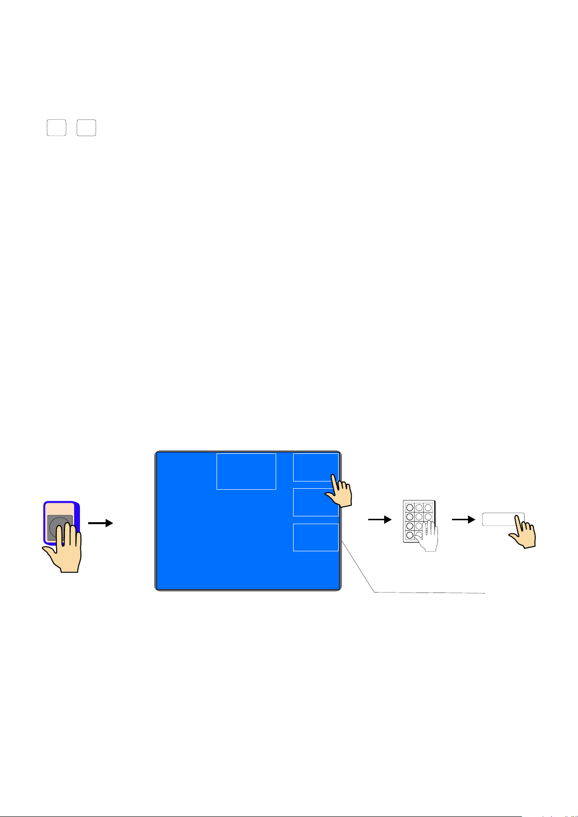
After pressing "OPERATOR" it is possible to choose operator name or continue by pressing START
OPERATOR
LOGIN
20.4.2011 8:30
20.4.2011 8:3020.4.2011 8:30
OPERATOR
OPERATOR
1
4
7
0
START
2
5
8
3
6
9
Model : ERN - 22 Gear : 6000
ENTERENTER
PRESS
GEAR
CHANGE
GEAR
CHANGE
MEM.POS.
OFF
MEM.POS.
OFF
5. WINDING OPERATION
5.1 MACHINE SWITCHING ON AND GEAR SETTING
After switching on (1) the start window shows
Display provides informations about, for what type of machine is controller set.
In this window we can change the set gear, which must be in ABSOLUTE ACCORDANCE with the
set of mechanical gear.

After pressing ENTER-button, the initial set is done, which means, that wire guide is shifted
left home (zero position), zero number of turns, zero step and the last set block is set.
Model : ERN - 22 Gear : 12000
ENTERENTER
PRESS
GEAR
CHANGE
GEAR
CHANGE
MEM.POS.
OFF
MEM.POS.
OFF
1200012000
30003000
60006000
Enter valid gear [max. rpm]!Enter valid gear [max. rpm]!
ENTER
8 / ERN C

5.2 WINDING DATA BACK UP WHILE ELECTRICITY DROP
In this window, we can activate the initial setting of the machine (wire guide position, number of
turns and step) for the back up values.
After the activation of this function (MEM.POS.ON) the initial setting will be actualized
for the values, memorized while electricity drop.
FOR USING THIS FUNCTION, THE MACHINE MUST BE EQUIPPED WITH
THE UNINTERRUPTIBLE POWER SUPPLY UNIT (UPS) AND THE REPORT OF
ELECTRICITY DROP (relay for POWER) MUST BE INSTALLED.
IF THE MACHINE IS NOT EQUIPPED BY THIS, THE ACTIVATION OF THIS FUNCTION
DOES NOT INFLUENCE THE INITIAL SETTING, WHICH IS STILL SET ON ZERO
VALUES.
9 / ERN C
Model : ERN - 22 Gear : 12000
ENTERENTER
PRESS
GEAR
CHANGE
GEAR
CHANGE
MEM.POS.
OFF
MEM.POS.
OFF
Model : ERN - 22 Gear : 12000
ENTERENTER
PRESS
GEAR
CHANGE
GEAR
CHANGE
MEM.POS.
ON
MEM.POS.
ON

5.3 WINDING AND VIEW WINDOW
These are two basic windows, in which we can start programmed cycle.
Repeated pressing of the ENTER-button caused the switching.
Winding window - provided actual information about winding process
View window - displayes the view of programmed step parameters
Winding is possible only in these two windows. If any other window is opened, the cycle start
is blocked.
5.4 EXPLANATION OF CONCEPTIONS STANDSTILL, START, STOP
STANDSTILL: State after switching on the machine and pressing ENTER, or after the step
finishing. Start from this state shifts program one step forward, generally.
E.g. when we are in the step 0, after starting, the step 1 is running.
START: Active run of some step type (winding,shift,jump and pause).
STOP: State after pressing the STOP-button (cycle interruption).
Repeated start activates interrupted run and there is no step shifting.
10 / ERN C
0.000.00
BACK
WINDING
BACK
WINDING
TOTAL
COUNTER
TOTAL
COUNTER
CORRECTION
N. of turns
CORRECTION
N. of turns
Step :Step : 22
0.00.0Position:
Next step: 3- SHIFT
Name: priklad2
Position:
Next step: 3- SHIFT
Name: priklad2
1: L - L NA1: L - L NA
2: L - L NA2: L - L NA
3: L - L NA3: L - L NA
4: L - L NA4: L - L NA
PEDAL : Pedal speed value taken from program !PEDAL : Pedal speed value taken from program !
TMTM
WINDINGWINDING
780.00780.00
Actual state
Step
Winding corrections
Number of turns
Wire guide position
and direction
Next step
Note
Inputs and outputs
Pedal speed
LAYERLAYER
CANCELCANCEL
Step :Step : 22
Turns: 780.00
L.Rev: 10.0 R.Rev: 30.0
Speed: 11965 Acc/Dec: 22
Pitch: 0.128
Cycle: Shield: CLOSE
Turns: 780.00
L.Rev: 10.0 R.Rev: 30.0
Speed: 11965 Acc/Dec: 22
Pitch: 0.128
Cycle: Shield: CLOSE
1: L - L NA1: L - L NA
2: L - L NA2: L - L NA
3: L - L NA3: L - L NA
4: L - L NA4: L - L NA
PEDAL : Pedal speed value taken from program !PEDAL : Pedal speed value taken from program !
TMTM
WINDINGWINDING

11 / ERN C
PC
5.5 Winding program selection
Winding program, we are just working with( we can perform winding or program creation )
is called ACTUAL PROGRAM. Actual program is located in so-called working part of memory.
Desired winding program can be loaded to the working part of memory either from internal
memory of the Winder, USB flash drive or a PC equiped by software GRAPHIC.
USB
PC with software GRAPHIC
Proceeding by program selection:
- internal memory - see section 7, page 50
- USB flash drive - see section 9, page 65
- PC - see GRAPHIC manual
Working part of memory
ACTUAL PROGRAM
NONVOLATILE MEMORY
Internal memory and working part of memory store data also when power is off !
CF CARD
PARTÍCIA D
5.5 START AND STOP OF WINDING CYCLE (PROGRAM)
Winding cycle is actuated by pressing START-button (4), or foot pedal.
There is a possibility to start program from each step. Required step is set up by the buttons
, or numeric keyboard.
STOP-button (5) interrupts the winding cycle. It is the priority button, what means, that the cycle
interruption at incorrect time (while deceleration), may cause inaccurate stopping and
positioning of the spindle.
Cycle interruption at the step "Winding" allows almost all corrections and adjustments.
Repeated cycle start by START-button or foot pedal activates step, where the program
interruption has been done, automatically.
Step types SHIFT, JUMP and PAUSE do not allow any corrections or adjustments
during interruption.
5.6 FOOT PEDAL
Winding machine may be equiped by following types of foot pedals:
Double foot pedal controls START, BRAKE RELEASE
- left pedal releases the spindle brake
- right pedal works as parallel START-button
Double foot pedal controls SPEED, BRAKE RELEASE
- left pedal releases the spindle brake
- right foot pedal controls spindle speed depending on pressing level
Maximal speed, accelerate and decelerate ramp may be set up by PEDAL button.
Speed set up like this, is valid for assigned block (program) and it is independent on speed
programmed, in single program steps. Explain as: max.speed (ordinary lower) set up by START
pedal may be different, then max.speed set up by START-button.
If we require the same max.pedal speed as speed, programmed in single program step, we
need to press multifunction button PROGRAM.
+
-
12 / ERN C
PEDALPEDAL 2233
5566
8899
CC
..
2233
5566
8899
CC
..
11
44
00
77
11
44
00
77
11
44
00
77
11
44
00
77ENTER
Dec. ramp for STOP button
STOP RAMP
1
STOP RAMP
1
PEDAL setup
PROGRAM
PEDAL setup
PROGRAM
Range: 0 - 12000 [rpm]
enter spindle speed !
Range: 0 - 12000 [rpm]
enter spindle speed !
250250
PROGRAM
SPEED
PROGRAM
SPEED
Accel/Dec
1
Accel/Dec
1

13 / ERN C
Max. pedal speed is controlled by values, programmed in single program steps, in this case.
Winding cycle start continuity
This option is utilized during winding start. Wire application and winding of the first turns is done by
pedal and then by pressing START-button (4) cycle continues.
5.7 PROTECTION SHIELD
Protection shield may be programmed as:
CLOSED
There is a possibility of winding only if the protection shield is closed.
When the shield is opened, the cycle is interrupted.
OPENED
There is a possibility of winding if the protection shield is opened, but the spindle speed will be limited
for safety value, automatically.
When the shield is closed during the winding, the cycle continues with the speed values programmed
previously.
Acceleration and deceleration ramp values are always taken from window PEDAL SETUP.
CODE
1
2
3
4
5
6
7
8
ACC.TIME DEC.TIME
1
2
3
4
6
8
10
12
0,5
1
1,5
2
3
4
5
6
( sec ) ( sec )
Accel. and dec. ramp for pedal
SPEEDSPEED
Accel/Dec
1
Accel/Dec
1
STOP RAMP
1
STOP RAMP
1
PEDAL setup
PROGRAM
PEDAL setup
PROGRAM
Pedal speed value
taken from program !
Pedal speed value
taken from program !
STOP RAMP
1
STOP RAMP
1
PEDAL setup
PROGRAM
PEDAL setup
PROGRAM
Range: 0 - 12000 [rpm]
Enter spindle speed !
Range: 0 - 12000 [rpm]
Enter spindle speed !
250250
PROGRAM
SPEED
PROGRAM
SPEED
Accel/Dec
1
Accel/Dec
1

5.9 WINDING CORRECTIONS
Program corrections and adjustments are allowed only in the state "STANDSTILL" or
"Winding STOP". Keys are blocked in other states. When there is peep warning after the
key pressing, the operation is illogical or inaccessible.
5.9.1 Spindle reference position setting
The spindle can be positioned in the range +- a few degrees and exact position
is kept for any amount of windings.
Reference (zero) spindle position is set up by follows:
- switch the brake-off by the switch (6)
- turn the spindle manually to the required position and return the switch (6) to the former position
- press RESET then ENTER
Note: When you switch the machine ON (by switch POWER or EMERGENCY STOP),
RESET is running automatically and the spindle position is taken as reference position.
5.9.2. Wire guide relative position setting
This correction shifts zero coordinate of the wire guide ( relative zero position). It allows you to correct
the wire gude position to be in accordance with the bobbin or winding tool.
Default : 5 mm
relative position 9mm
relative position 5mm
relative position 1mm
the same wire guide coordinate depending up relative position
relative zero
0 0 0
14 / ERN C

15 / ERN C
CORRCORR
2233
5566
8899
CC
..
2233
5566
8899
CC
..
11
44
00
77
11
44
00
77
11
44
00
77
11
44
00
77ENTER
+
-
or
COPY
STEP
COPY
STEP
Range: 1.0 - 210.0 [mm]
Setup relative position !
Range: 1.0 - 210.0 [mm]
Setup relative position !
5.05.0
GLOBAL
CHANGE
GLOBAL
CHANGE
Step:Step: 22WIRE GUIDE
RELATIVE
POSITION
WIRE GUIDE
RELATIVE
POSITION
NEXT
(1)
NEXT
(1)
68.3068.30
BACK
WINDING
BACK
WINDING
TOTAL
COUNTER
TOTAL
COUNTER
CORRECTION
N.of Turns
CORRECTION
N.of Turns
Step :Step : 22
24.424.4
Position:
Next step: 3- SHIFT
Name: priklad2
Position:
Next step: 3- SHIFT
Name: priklad2
1: L - L NA1: L - L NA
2: L - L NA2: L - L NA
3: L - L NA3: L - L NA
4: L - L NA4: L - L NA
PEDAL : Pedal speed taken from program !PEDAL : Pedal speed taken from program !
TMTM
WINDING
STOP
WINDING
STOP
780.00780.00
RESETRESET
Range: 0 - 99990 [turn]
Enter number of turns !
Range: 0 - 99990 [turn]
Enter number of turns !
68.3068.30
Step :Step : 22CORRECTION
COUNTER
CORRECTION
COUNTER
2233
5566
8899
CC
..
2233
5566
8899
CC
..
11
44
00
77
11
44
00
77
11
44
00
77
11
44
00
77ENTER
+
-
Holding the buttons pressed (cca 0,5 s) moves the wire guide continuously.
5.9.3. Number of turns correction
We can change the number of turns counted actually.
Correction of decimal turn number e.g. XX.3 to XX.0 without adequate spindle turn, leads to the
loss of reference position..
Multifunction RESET-button set to zero actual counter state.

5.9.4 Total counter
We can switch between TOTAL COUNTER and COUNTER. TOTAL COUNTER counts all spindle turns
until it is set to zero by RESET, or is set differently by numeric keyboard.
Both counters are independent. By switching is only displayed one of it !
16 / ERN C
68.3068.30
BACK
WINDING
BACK
WINDING
TOTAL
COUNTER
TOTAL
COUNTER
CORRECTION
N.of Turns
CORRECTION
N.of Turns
Step :Step : 22
24.424.4
Position:
Next step: 3- SHIFT
Name: priklad2
Position:
Next step: 3- SHIFT
Name: priklad2
1: L - L NA1: L - L NA
2: L - L NA2: L - L NA
3: L - L NA3: L - L NA
4: L - L NA4: L - L NA
PEDAL : Pedal speed taken from program !PEDAL : Pedal speed taken from program !
TMTM
WINDING
STOP
WINDING
STOP
780.00780.00
68.30T68.30T
BACK
WINDING
BACK
WINDING
COUNTERCOUNTER
CORRECTION
N.of Turns
CORRECTION
N.of Turns
Step :Step : 22
24.424.4
Position:
Next step: 3- SHIFT
Name: priklad2
Position:
Next step: 3- SHIFT
Name: priklad2
1: L - L NA1: L - L NA
2: L - L NA2: L - L NA
3: L - L NA3: L - L NA
4: L - L NA4: L - L NA
PEDAL : Pedal speed taken from program !PEDAL : Pedal speed taken from program !
TMTM
WINDING
STOP
WINDING
STOP
780.00780.00
68.3068.30
BACK
WINDING
BACK
WINDING
COUNTERCOUNTER
CORRECTION
N.of Turns
CORRECTION
N.of Turns
Step :Step : 22
24.424.4
Position:
Next step: 3- SHIFT
Name: priklad2
Position:
Next step: 3- SHIFT
Name: priklad2
1: L - L NA1: L - L NA
2: L - L NA2: L - L NA
3: L - L NA3: L - L NA
4: L - L NA4: L - L NA
PEDAL : Pedal speed taken from program !PEDAL : Pedal speed taken from program !
TMTM
WINDING
STOP
WINDING
STOP
780.00780.00

2233
5566
8899
CC
..
2233
5566
8899
CC
..
11
44
00
77
11
44
00
77
11
44
00
77
11
44
00
77
ENTER
+
-
or
Range: 1.0 - 210.0 [mm]
Setup wire guide position !
Range: 1.0 - 210.0 [mm]
Setup wire guide position !
24.424.4
Step:Step: 22WIRE GUIDE
POSITION
WIRE GUIDE
POSITION
17 / ERN C
WIRE GUIDE
POSITION
WIRE GUIDE
POSITION
WIRE GUIDE
DIRECTION
WIRE GUIDE
DIRECTION
5.9.5. Wire guide correction
Correction allows you to correct the wire guide position while winding process.
+
-
Holding the buttons pressed (cca 0,5 s) moves the wire guide continuously.
5.9.6. Wire guide direction change
Correction allows you to change the direction of wire guide while winding.
68.3068.30
BACK
WINDING
BACK
WINDING
TOTAL
COUNTER
TOTAL
COUNTER
CORRECTION
N.of Turns
CORRECTION
N.of Turns
Step :Step : 22
24.424.4
Position:
Next step: 3- SHIFT
Name: priklad2
Position:
Next step: 3- SHIFT
Name: priklad2
1: L - L NA1: L - L NA
2: L - L NA2: L - L NA
3: L - L NA3: L - L NA
4: L - L NA4: L - L NA
PEDAL : Pedal speed taken from program !PEDAL : Pedal speed taken from program !
TMTM
WINDING
STOP
WINDING
STOP
780.00780.00
This manual suits for next models
5
Table of contents
Other TPC Industrial Equipment manuals


