TPI Corporation 3900WW28 User manual

LOCATION OF HEATER
Heaters should be located to provide a blanket of
heat over the coldest wall of the room, preferably
on a outside wall under a window.
CAUTIONS AND WARNING STATEMENTS
1. Wiring procedures and connections should be
in accordance with national and local codes
having jurisdiction. Note: all baseboards must
be grounded in accordance with article 250 of
the National Electrical Code.
2. Do not install baseboard heater below electrical
convenience receptacles (outlets).
3. Do not install heaters against combustible low
density cellulose fiberboard surfaces.
4. High temperatures are present at outlet air
openings. Keep electrical cords, drapes and
other furnishings or objects clear of these
openings.
5. To reduce risk of fire, do not store or use
gasoline or other flammable vapors and liguids
in the vicinity of the heater.
6. Heaters are designed for surface mounting only.
Do not recess the heaters into the wall.
7. Do not tamper with or remove the temperature
limitingdevice.
RECOMMENDATIONS FOR DRAPE
PLACEMENT NEAR BASEBOARD HEATER
1. Allowminimumclearanceof1”fromdrapestoceiling
and to top of floor covering to permit air circulation
(Example 1, Figure 1).
2. Hang full length drapes to provide a minimum of 2”
air space between heater front and nearest drape
fold as shown in Example 1, Figure 1.
3. Hang short drapes to provide minimum of 6”
clearance between bottom of drapes and top of
heater, preferably more (Example 2, Figure 1).
4. Do not under any condition allow drapery to come
incontactwithheater. Somefabricsdiscolorin time
from exposure sunlight or warm air. Check to make
sure drapery material will not discolor, shrink, or
stretch upon extended (1000 hour) exposure to
temperatures of 200oF.
Heaters may be mounted directly to any floor
surface, including carpeting. Wall to wall carpet
(maximum thickness 3/4”) may extend under or to
the front of the baseboard heater. This is provided
the flooring material does not obstruct air flow to
theheater.
5. Do not install vinyl curtains, drapes or blinds above
the heater as they may discolor or deform.
HYDRONIC BASEBOARD HEATER
Commercial / Residential
IMPORTANT:OWNER SHOULDRETAINTHESE INSTRUCTIONSFOR FUTUREREFERENCE
INSTALLATION
INSTRUCTIONS
ATTENTION: Read carefully before attempting to
install, operate or service the Baseboard Heater.
Retain these instructions for future reference.
REV: 081403 - PN 8920

THE FOLLOWING STEPS SHOULD BE TAKEN FOR INSTALLATION
Verify input voltage and name plate voltage of heater for compatibility. Wiring can be done from either end of
heater. Ainside or outside corner section is available for right angle mounting of two baseboard heaters and
allowance should be made for locating wiring. See Figure 2 for knockout locations.
MOUNTING AND WIRING
1. Position the heater in the required location
preferably on an outside wall under a window.
2. Determinewhichendthe powersupply willenter
theheater. (This heatercanbewiredfromeither
end). Drill the appropriate hole into the wall or
floorfor the power supply, see Figure 2 for
knockoutlocations. Makesurethattheelectrical
power supply is disconnected at the circuit
breakerpanel.
3. Remove the wiring compartment cover. If the
power supply is entering on the back of the
heater remove the knockout, install the cable
connector (not provided) and feed the wire
through the connector. Leave about 6 inches
of wire extending into the box for connection. If
the power supply enters on the bottom of the
heater, remove plug button from the bottom of
the wiring compartment, install the cable
connector (not provided) and feed the wire
throughtheconnector. Pushanyexcess cable
into the wall or floor.
4. Remove the front cover of the baseboard. The
front cover is snapped on the element retainer
brackets. Position the heater on the wall and
determine the stud locations. Drill 3/16 inch
holesintherearenclosure using the drill guide,
seeFigure2. Securethe heater to the wallwith
minimum #8 screws 1 inch long. Snug the
heater up against he wall then back the screws
off about 1/2 inch to allow for expasion. If a
studisnotavailableusetheappropriatefastener
such as toggle bolts or molly screw anchors
for hollow walls or screws and anchors for
masonry walls.
5. Replace the front cover by snapping it over the
element retaining brackets.
6. Remove the wire nut in the wiring compartment
and connect the power supply as shown in the
wiring diagrams, Figure 3. If you are using one
of the field installed accessories, refer to the
wiring diagram provided with the accessory.
7. Replace the wiring compartment cover and
restorepowerto the circuit. Turnthethermostat
up and wait 2-3 minutes to see if the heater is
operatingproperly.If the heaterisnotoperating
disconnect the power at the circuit breaker box
and check wiring.
CLEANING INSTRUCTIONS
At the beginning of each heating season, it is
recommendedthat heatersbecleaned toeliminate
any accumulation of dust or lint. Before cleaning,
makesurethe powers isOFFatthe circuit breaker
panelandtheheatingelementcool. Donotremove
frontcoverduringcleaning. Use thenarrow suction
attachment of the vacuum cleaner and move from
end to end and above and below fins and cabinet.
When cleaning is complete, turn power ON.
IN CASE OF PRODUCT FAILURE: It is the
obligation of the owner to furnish to the company
withinthe designatedwarranty period,thefollowing
information:
1. Model number and date of manufacture of
product involved and date of purchase.
2. Complete description of the problem
encountered with product. Upon receipt of the
above,thecompanywill replyto theowner within
aperiodnot to exceedfifteen(15) working days,
the action to be taken by owner. When
requested,itshall be the obligation oftheowner
toreturn thedefectiveparttothe companywithin
thirty(30)daysafterits removal, or otherwise to
follow instruction from the company. Return
parts to the appropriate service center.

FIGURE1 FIGURE2
FIGURE3

INSTALLATION INSTRUCTIONS
WIREWAYADAPTER
MODEL 3900WW24,28,36,40,48,60,72,84,96,108AND 120
INSTALLATION
INSTRUCTIONS
CAUTION: Disconnect supply service to baseboard to avoid electrical shock.
All wiring connections must conform to the National Electric Code and local codes having jurisdiction.
1. Remove junction box covers.
2. Remove plug on bottom of junction box and insert the snap bushing provided.
3. Using means to protect heater finish, place baseboard face down. Lay wires in wireway and feed wire
through bushings into junction box allowing 6” min. of wire in junction box.
4. Attach wireway adaptor to baseboard with screws provided.
5. Mount baseboard to wall (refer to baseboard installation instructions).
6. Complete wiring connections inside junction boxes for continuous parallel wiring.
7. Re-install junction box covers and check heater for proper operation.
INSTRUCTIONS FOR PRE-INSTALLED WIREWAY ADAPTER
1. Remove junction box covers.
2. Using means to protect the heater finish, place baseboard face down. Remove the adapter screws
and adapter.
3. Lay wires into bottom of baseboard and feed through bushings into junction boxes allowing 6” min.
of wire into box.
4. Re-install wireway adapter and secure with previously removed screws. Proceed with steps 5, 6
and 7 above.
8923 - REV. 110206
INSTALLATION
INSTRUCTIONS
IMPORTANT: OWNER SHOULD RETAIN THESE INSTRUCTIONS FOR FUTURE REFERENCE
WIRE WAY
BUSHING
SCREW

INSTALLATION
INSTRUCTIONS INSTALLATION
INSTRUCTIONS
INSTALLATION INSTRUCTIONS
TRANSFER SWITCH WITH RECEPTACLE
MODEL 3900AC
CAUTION: Disconnect supply service to baseboard to avoid electrical shock.
All wiring connections must conform to the National Electric Code and local codes having
jurisdiction.
NOTES:
*Do not eliminate or bypass the thermal cutout.
*Do not exceed the nameplate rating.
*The inbuilt accessory can be mounted in either end of the baseboard heater.
1. Remove the baseboard junction box cover and retain the screw.
2. Remove the wire nut in the junction box (Do not remove the crimp nut connection).
3. Make the connections per the wiring diagram. Connect the wires marked “Line” to the supply.
Connect the wires marked “Load” to the baseboard. Make sure all connections are secure.
4. Install transfer switch/receptacle cover assembly to baseboard junction box and secure with screw
previously removed.
5. Restore power and check for proper operation.
8924 - REV. 110206
IMPORTANT: OWNER SHOULD RETAIN THESE INSTRUCTIONS FOR FUTURE REFERENCE
SHOWN WIRED RIGHT END
ELEMENT
OVER TEMP. LIMIT CONTROL
LEFT JUNCTION BOX
GND
RIGHT JUNCTION BOX
3700 SERIES BASEBOARD
LEFT JUNCTION BOX RIGHT JUNCTION BOX
CRIMP
NUT ELEMENT
TEMP.
LIMITING
DEVICE
SHOWN WIRED LEFT END
CRIMP
NUT
WIRE NUT
GND
3900 SERIES BASEBOARD
240V SUPPLY
MAX. 20A
BRANCH CIRCUIT
GND
WIRE
NUT
GND
240V SUPPLY
MAX. 20A
BRANCH CIRCUIT

SHOWN WIRED LEFT END
ELEMENT
OVER TEMP. LIMIT CONTROL
GND
LEFT JUNCTION BOX RIGHT JUNCTION BOX
3700 SERIES BASEBOARD
SUPPLY
SHOWN WIRED LEFT END
ELEMENT
OVER TEMP. LIMIT CONTROL
GND
LEFT JUNCTION BOX RIGHT JUNCTION BOX
SUPPLY
DOUBLE POLE
THERMOSTAT
SINGLE POLE
THERMOSTAT
CRIMP
NUT ELEMENT
TEMP.
LIMITING
DEVICE
LEFT JUNCTION BOX RIGHT JUNCTION BOX
LEFT JUNCTION BOX RIGHT JUNCTION BOX
GND
SUPPLY
DOUBLE POLE
THERMOSTAT
GND
SUPPLY
SINGLE POLE
THERMOSTAT
CRIMP
NUT ELEMENT
TEMP.
LIMITING
DEVICE
3700 SERIES BASEBOARD
3900 SERIES BASEBOARD
3900 SERIES BASEBOARD
SHOWN WIRED LEFT END
SHOWN WIRED LEFT END
GND
GND
GND
GND
CRIMP
NUT
CRIMP
NUT
WIRE
NUT
WIRE
NUT WIRE
NUT
WIRE
NUT
INSTALLATION
INSTRUCTIONS INSTALLATION
INSTRUCTIONS
INSTALLATION INSTRUCTIONS
INBUILT THERMOSTATS
MODELS 3700T1, 3700T2
3900T1, 3900T2
SAVE THSESE INSTRUCTIONS
CAUTION: Disconnect supply service to baseboard to avoid electrical shock.
All wiring connections must conform to the National Electric Code and local codes having
jurisdiction.
NOTES:
*Do not eliminate or bypass the thermal cutout.
*Do not exceed the nameplate rating.
*The inbuilt accessory can be mounted in either end of the baseboard heater.
1. Remove the baseboard junction box cover and retain the screw.
2. Remove the wire nut in the junction box (Do not remove the crimp nut connection).
3. Make the electrical connections per the wiring diagram. Connect the red lead wire(s) to supply wires and the
black lead wire(s) to the load.
4. Install the thermostat assembly and knob to the baseboard and secure with screw previously removed.
5. Restore power to baseboard and check for proper operation.
6. Thermostat operation: Turn thermostat shaft fully clockwise. When the room has reached the desired comfort
level, slowly turn the thermostat shaft counter-clockwise until the heater turns off (a faint click will be heard).
One or two minor adjustments may be required.
7. For tamper resistant operation, remove the knob and install the plug provided.
8925 - REV. 110206
IMPORTANT: OWNER SHOULD RETAIN THESE INSTRUCTIONS FOR FUTURE REFERENCE

INSTALLATION
INSTRUCTIONS INSTALLATION
INSTRUCTIONS
INSTALLATION INSTRUCTIONS
LOW VOLTAGE RELAY
MODEL3900LV120,208,240,277
CAUTION: Disconnect supply service to baseboard to avoid electrical shock.
All wiring connections must conform to the National Electric Code and local codes having
jurisdiction.
1. Remove the baseboard junction box cover and retain the screw.
2. Mount relay in junctions box on the top screw track with the screws provided. Mount the relay
so that the wires are at the top of the baseboard.
3. Remove wire nut and wire as shown in diagram below.
4. Replace covers and restore power to the unit, check for proper operation.
8926 - REV. 110206
IMPORTANT: OWNER SHOULD RETAIN THESE INSTRUCTIONS FOR FUTURE REFERENCE
SHOWN WIRED LEFT END
ELEMENT
BLACK
BLUE
RED
LOW
VOLTAGE
THERMOSTAT
WIRE
WIRE
NUT
CONTROL SECTION
OVER TEMP. LIMIT CONTROL
GND
LEFT JUNCTION BOX
GND
RIGHT JUNCTION BOX
3700 SERIES BASEBOARD
LEFT JUNCTION BOX RIGHT JUNCTION BOX
CRIMP
NUT ELEMENT
TEMP.
LIMITING
DEVICE
SHOWN WIRED LEFT END
CRIMP
NUT
WIRE NUT
GND GND
3900 SERIES BASEBOARD
SUPPLY BLACK
BLUE
RED
LOW
VOLTAGE
THERMOSTAT
WIRE WIRE
NUT
GND
SUPPLY

INSTALLATION
INSTRUCTIONS
INSTALLATION INSTRUCTIONS
INBUILT DUPLEX RECEPTACLE
MODEL 3900REC
SAVE THESE INSTRUCTIONS
CAUTION: Disconnect supply service to baseboard to avoid electrical shock.
All wiring connections must conform to the National Electric Code and local codes having jurisdiction.
NOTE: The receptacle must be connected to a branch circuit other than the baseboard heater
circuit, having over current protection in accordance with National Electric Code.
1. The receptacle cover assembly can be mounted in the left or right hand junction box.
2. Remove the baseboard heater junction box cover and retain the screw.
3. Attach the 120V branch supply leads and ground lead to the receptacle. Use copper
conductors only.
4. Install receptacle cover assembly to the baseboard junction box and secure with previously
removed screw.
5. Restore power and check for proper operation.
8927 - REV. 110206
HEATER
SUPPLY
THERMAL CUTOUT
DUPLEX
RECEPTACLE
GND
ELEMENT
INSTALLATION
INSTRUCTIONS
IMPORTANT: OWNER SHOULD RETAIN THESE INSTRUCTIONS FOR FUTURE REFERENCE

CRIMP NUT
WIRE NUT
GND GND
3900 SERIES BASEBOARD
SUPPLY
DOUBLE POLE
DISCONNECT
SWITCH
SHOWN WIRED RIGHT END
ELEMENT
OVER TEMP. LIMIT CONTROL
GND
LEFT JUNCTION BOX
GND
RIGHT JUNCTION BOX
3700 SERIES BASEBOARD
SUPPLY
DOUBLE POLE
DISCONNECT
SWITCH
LEFT JUNCTION BOX RIGHT JUNCTION BOX
CRIMP
NUT ELEMENT
TEMP.
LIMITING
DEVICE
SHOWN WIRED LEFT END
INSTALLATION
INSTRUCTIONS INSTALLATION
INSTRUCTIONS
INSTALLATION INSTRUCTIONS
DISCONNECT SWITCH MODEL 3900DS
CAUTION: Disconnect supply service to baseboard to avoid electrical shock.
All wiring connections must conform to the National Electric Code and local codes having
jurisdiction.
NOTES:
*Do not eliminate or bypass the thermal cutout.
*Do not exceed the nameplate rating.
*The inbuilt accessory can be mounted in either end of the baseboard heater.
1. Remove the baseboard junction box cover and retain the screw.
2. Remove the wire nut in the junction box (Do not remove the crimp nut connection).
3. Make the connections per the wiring diagram. Connect the wires marked “Line” to the supply.
Connect the wires marked “Load” to the baseboard. Make sure all connections are secure.
4. Install disconnect switch cover assembly to baseboard junction box and secure with screw
previously removed.
5. Restore power and check for proper operation.
8928 - REV. 110206
IMPORTANT: OWNER SHOULD RETAIN THESE INSTRUCTIONS FOR FUTURE REFERENCE

INSTALLATION INSTRUCTIONS
INSIDE/OUTSIDE CORNER SECTIONS
MODELS 3900ICS, 3900OCS
CAUTION: Disconnect supply service to baseboard to avoid electrical shock. All wiring
connections must conform to the National Electric Code and local codes having jurisdiction.
1. Remove junction box covers and the end plates from baseboard heaters that are to be
joined by the corner section.
2. Remove a knockout from the exposed end of one of the baseboard junction boxes and
insert the snap bushing provided.
3. Remove the front cover of the corner section mount the corner section to the wall.
4. Position the baseboard(s) next to the corner section and feed the corner section ground
wire through the bushing.
5. Mount and wire the baseboard according to the baseboard installation instructions.
SNAP BUSHING
SNAP BUSHING
FORM: 8929 - REV 081403

CAUTION: Disconnect supply service to baseboard to avoid electrical shock.All wiring connections must
conform to the National Electric Code and local codes having jurisdiction.
1. Remove cover from control section, the junction box cover and end plate of the baseboard
and retain screws.
2. Remove knockout from side of control section adjacent to baseboard and the knockout in
junction box of the baseboard.
3. Mount the control section on the wall adjacent to the baseboard. Using the drill guide, drill
two 3/16" holes in the back of the control section and mount to the wall with the appropriate
fasteners. Insert the snap bushing in the knockout holes.
4. Wire the desired accessory per the installation instructions and replace covers, using the end
plate of the baseboard for the exposed end of the control section.
5. Restore the power and check for proper operation.
WIRE WAY SCREW
BUSHING
KNOCKOUT
DRILL GUIDE
FORM: 8930
INSTALLATION
INSTRUCTIONS
INSTALLATION INSTRUCTIONS
4" CONTROL SECTION
MODEL 3900CS
IMPORTANT: OWNER SHOULD RETAIN THESE INSTRUCTIONS FOR FUTURE REFERENCE

INSTALLATION
INSTRUCTIONS INSTALLATION
INSTRUCTIONS
INSTALLATION INSTRUCTIONS
BLANK SECTION
MODEL 39BS24,28,36,40,48,60,72,84,96,108AND 120
CAUTION: Disconnect supply service to baseboard to avoid electrical shock.
All wiring connections must conform to the National Electric Code and local codes having
jurisdiction.
NOTE:The baseboard blank section mounts against the wall similar to the baseboard. When making
wiring connection: for wiring a single baseboard and the supply is through the blank section or
when wirng for continuous parrallel connections for multiple baseboard installation, then a wire-
way adapter must be used. (See wireway adapter instructions).
1. Remove appropriate junction box covers from the baseboard(s) and blank section.
2. Remove knockouts from junction boxes as required and insert snap bushing(s)Attach green ground
lead(s) from blank section to baseboard for continuity of ground.
3. Wire baseboard(s) as required and install covers.
5. Restore power and check for proper operation.
8931 - REV. 110706
IMPORTANT: OWNER SHOULD RETAIN THESE INSTRUCTIONS FOR FUTURE REFERENCE
BLANK SECTION
ELEMENT
OVER TEMP. LIMIT CONTROL
GND
LEFT JUNCTION BOX
GND
RIGHT JUNCTION BOX
LEFT JUNCTION BOX RIGHT JUNCTION BOX
CRIMP
NUT ELEMENT
TEMP.
LIMITING
DEVICE
SHOWN WIRED LEFT END
GND
BLANK SECTION
GND GND
L/H JUNCTION BOX R/H JUNCTION BOX
CRIMP
NUT ELEMENT
TEMP.
LIMITING
DEVICE
GND GND
SUPPLY
WIRE
NUT
WIRE
NUT
WIRE
NUT
L/H JUNCTION BOX R/H JUNCTION BOX
BLANK SECTION
SUPPLY
LEFT JUNCTION BOX RIGHT JUNCTION BOX
GND
WIREWAY ADAPTER
GND
3700 SERIES BASEBOARD
L/H JUNCTION BOXR/H JUNCTION BOX
GND
GND
BLANK SECTION
GND GND
L/H JUNCTION BOX R/H JUNCTION BOX
GND GND
L/H JUNCTION BOX R/H JUNCTION BOX
CRIMP NUT
WIRE NUT
GND GND
3900 SERIES BASEBOARD
SUPPLY
LEFT JUNCTION BOX RIGHT JUNCTION BOX
GND GND
WIREWAY ADAPTER
L/H JUNCTION BOXR/H JUNCTION BOX
CRIMP
NUT
ELEMENT
TEMP.
LIMITING
DEVICE
GND
ELEMENT
OVER TEMP. LIMIT CONTROL
CRIMP NUT
ELEMENT
OVER TEMP. LIMIT CONTROL
CRIMP NUT
SUPPLY

LOCATION OF HEATER
Heaters should be located to provide a blanket of
heat over the coldest wall of the room, preferably
on a outside wall under a window.
CAUTIONS AND WARNING STATEMENTS
1. Wiring procedures and connections should be
in accordance with national and local codes
having jurisdiction. Note: all baseboards must
be grounded in accordance with article 250 of
the National Electrical Code.
2. Do not install baseboard heater below electrical
convenience receptacles (outlets).
3. Do not install heaters against combustible low
density cellulose fiberboard surfaces.
4. High temperatures are present at outlet air
openings. Keep electrical cords, drapes and
other furnishings or objects clear of these
openings.
5. To reduce risk of fire, do not store or use
gasoline or other flammable vapors and liguids
in the vicinity of the heater.
6. Heaters are designed for surface mounting only.
Do not recess the heaters into the wall.
7. Do not tamper with or remove the temperature
limitingdevice.
RECOMMENDATIONS FOR DRAPE
PLACEMENT NEAR BASEBOARD HEATER
1. Allowminimumclearanceof1”fromdrapestoceiling
and to top of floor covering to permit air circulation
(Example 1, Figure 1).
2. Hang full length drapes to provide a minimum of 2”
air space between heater front and nearest drape
fold as shown in Example 1, Figure 1.
3. Hang short drapes to provide minimum of 6”
clearance between bottom of drapes and top of
heater, preferably more (Example 2, Figure 1).
4. Do not under any condition allow drapery to come
incontactwithheater. Somefabricsdiscolorin time
from exposure sunlight or warm air. Check to make
sure drapery material will not discolor, shrink, or
stretch upon extended (1000 hour) exposure to
temperatures of 200oF.
Heaters may be mounted directly to any floor
surface, including carpeting. Wall to wall carpet
(maximum thickness 3/4”) may extend under or to
the front of the baseboard heater. This is provided
the flooring material does not obstruct air flow to
theheater.
5. Do not install vinyl curtains, drapes or blinds above
the heater as they may discolor or deform.
Commercial/Residential
IMPORTANT: OWNERSHOULDRETAIN THESEINSTRUCTIONSFOR FUTUREREFERENCE
INSTALLATION
INSTRUCTIONS
ATTENTION: Read carefully before attempting to
install, operate or service the Baseboard Heater.
Retain these instructions for future reference.
18981 - REV.
3700 SERIES ELECTRIC BASEBOARD HEATER

THE FOLLOWING STEPS SHOULD BE TAKEN FOR INSTALLATION
Verify input voltage and name plate voltage of heater for compatibility. Wiring can be done from either end of
heater. Ainside or outside corner section is available for right angle mounting of two baseboard heaters and
allowance should be made for locating wiring. See Figure 2 for knockout locations.
MOUNTING AND WIRING
1. Position the heater in the required location
preferably on an outside wall under a window.
2. Determinewhichendthe powersupply willenter
theheater. (This heatercanbewiredfromeither
end). Drill the appropriate hole into the wall or
floorfor the power supply, see Figure 2 for
knockoutlocations. Makesurethattheelectrical
power supply is disconnected at the circuit
breakerpanel.
3. Remove the wiring compartment cover. If the
power supply is entering on the back of the
heater remove the knockout, install the cable
connector (not provided) and feed the wire
through the connector. Leave about 6 inches
of wire extending into the box for connection. If
the power supply enters on the bottom of the
heater, remove plug button from the bottom of
the wiring compartment, install the cable
connector (not provided) and feed the wire
throughtheconnector. Pushanyexcess cable
into the wall or floor.
4. Remove the front cover of the baseboard. The
front cover is snapped on the element retainer
brackets. Position the heater on the wall and
determine the stud locations. Drill 3/16 inch
holesintherearenclosure using the drill guide,
seeFigure2. Securethe heater to the wallwith
minimum #8 screws 1 inch long. Snug the
heater up against he wall then back the screws
off about 1/2 inch to allow for expasion. If a
studisnotavailableusetheappropriatefastener
such as toggle bolts or molly screw anchors
for hollow walls or screws and anchors for
masonry walls.
5. Replace the front cover by snapping it over the
element retaining brackets.
6. Remove the wire nut in the wiring compartment
and connect the power supply as shown in the
wiring diagrams, Figure 3. If you are using one
of the field installed accessories, refer to the
wiring diagram provided with the accessory.
7. Replace the wiring compartment cover and
restorepowerto the circuit. Turnthethermostat
up and wait 2-3 minutes to see if the heater is
operatingproperly.If the heaterisnotoperating
disconnect the power at the circuit breaker box
and check wiring.
CLEANING INSTRUCTIONS
At the beginning of each heating season, it is
recommendedthat heatersbecleaned toeliminate
any accumulation of dust or lint. Before cleaning,
makesurethe powers isOFFatthe circuit breaker
panelandtheheatingelementcool. Donotremove
frontcoverduringcleaning. Use thenarrow suction
attachment of the vacuum cleaner and move from
end to end and above and below fins and cabinet.
When cleaning is complete, turn power ON.
IN CASE OF PRODUCT FAILURE: It is the
obligation of the owner to furnish to the company
withinthe designatedwarranty period,thefollowing
information:
1. Model number and date of manufacture of
product involved and date of purchase.
2. Complete description of the problem
encountered with product. Upon receipt of the
above,thecompanywill replyto theowner within
aperiodnot to exceedfifteen(15) working days,
the action to be taken by owner. When
requested,itshall be the obligation oftheowner
toreturn thedefectiveparttothe companywithin
thirty(30)daysafterits removal, or otherwise to
follow instruction from the company. Return
parts to the appropriate service center.
2 8981 - REV.

FIGURE 1 FIGURE 2
FIGURE 3
4.10
2.42
TEMPERATURE LIMITING DEVICE
1.43
1.60
WIRE NUT
2.1
ELEMENT
TEMP. LIMIT DEVICE
GND GND
CRIMP
NUT
WIRE
NUT
ELEMENT
TEMP. LIMIT DEVICE
GND
CRIMP
NUT
ELEMENT
TEMP. LIMIT DEVICE
CRIMP
NUT
WIRE
NUT
L1
L2(N)
GND GND
GND
MULTIPLEUNITWIRING
WIRINGDIAGRAM
8981 - REV.
3
This manual suits for next models
10
Table of contents
Other TPI Corporation Heater manuals

TPI Corporation
TPI Corporation CEH/3380 Series User manual
TPI Corporation
TPI Corporation Fostoria OCH2 Series User manual
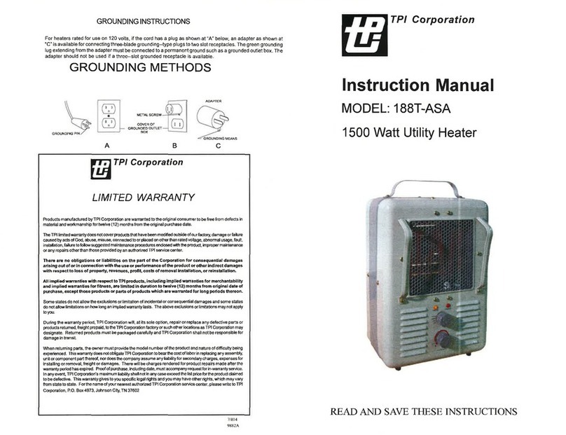
TPI Corporation
TPI Corporation 188T-ASA User manual

TPI Corporation
TPI Corporation FES-4548-3 User manual
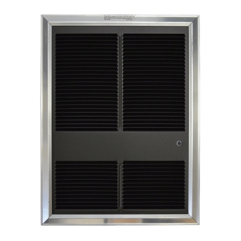
TPI Corporation
TPI Corporation AFA / 3320 Series User manual

TPI Corporation
TPI Corporation 3200 Series User manual
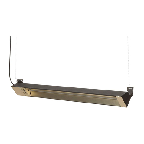
TPI Corporation
TPI Corporation Fostoria OCH Series User manual
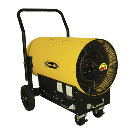
TPI Corporation
TPI Corporation FES-4548-3 User manual
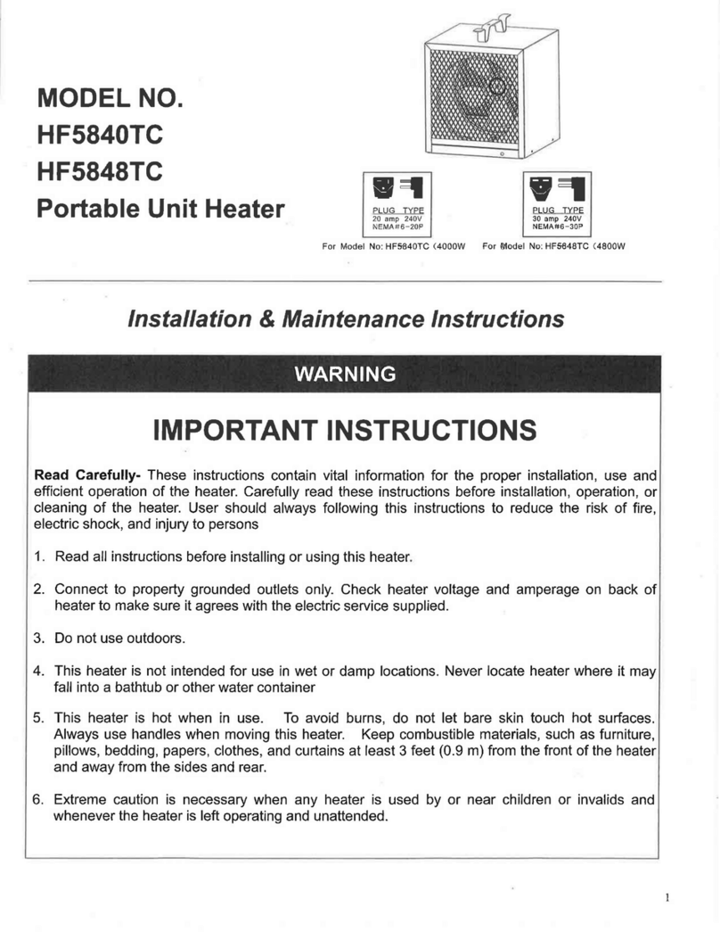
TPI Corporation
TPI Corporation HF5840TC Installation and operating instructions

