manuals.online logo
Brands
  1. Home
  2. •
  3. Brands
  4. •
  5. TPI Corporation
  6. •
  7. Heater
  8. •
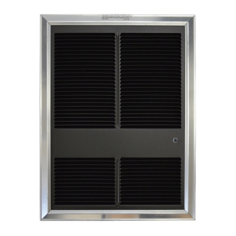
  9. TPI Corporation CEH/3380 Series User manual

TPI Corporation CEH/3380 Series User manual

FORM 9585 REV 10/18 ECO 1-74721 OF 3
CEH / 3380 SERIES
CEILING HEATER INSTALLATION
INSTRUCTIONS
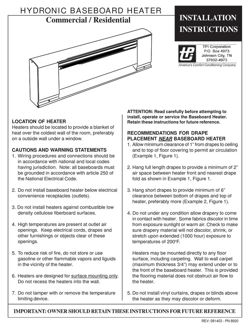
Location of Heater:
Heaters are designed for surface, recessed or “T-bar” ceiling
mounting. Heaters must be mounted to provide a minimum
clearance of 8” from the intake or exhaust end or from the
sides of the heater to the nearest wall or obstruction. For
T-Bar installation (Fig. 3), use the optional T-Bar frame CEH-
TBF / TB3380. Select a 2’ x 2’ section of framework in such
a location that the minimum 8” spacing is maintained. Follow
the installation wiring diagram carefully. A green ground
lead is provided. Insure that supply voltage matches voltage
rating on the label of the heater. Disconnect power supply at
breaker box before installation.
Mounting Instructions:
1. Disassemble heater as shown in Fig. 1 & Fig. 2.
2. Flush Mounting (Fig. 2). Provide opening in ceiling
14
1/4” wide by 19 5/16” long. Note that the direction of
air ow is parallel to the 19 5/16” side of the opening.
Depth must be a minimum of 4” from the nished ceiling
surface. Install rough-in box into the opening so that the
anges are ush with nished ceiling surface. Secure
rough-in box with nails, screws or appropriate fasteners.
Wiring may be brought into the box from either end using
the knockouts provided.
3. Surface Mounting (Fig. 1). Insert rough-in box into
surface adapter CEHA /3380EX33. Secure rough-in box
into ceiling through holes provided in the back. Be sure
that rough-in box is centered in the surface adapter.
Bring wiring in through air outlet end knockouts only.
4. Remove all construction dirt and debris from inside the heater.
5. Place heater assembly inside the rough-in box and
secure
with
six screws.
Wiring Instructions:
6. All wiring must conform to National and local electrical
codes.
With Disconnect Reference WD-1
A. Attach service leads to two black leads (L1 & L2) on
208-240 volt models and to white (L1) and black (L2)
on 120-277 volt models, with approved connectors.
Connect ground lead to green ground wire with approved
connectors.
B. Run service leads from remote thermostat and connect
to lead wire T1 & T2 with approved connectors. Replace
wiring compartment cover.
Without Disconnect Reference WD-2
For proper fan operation, three conductor wires and a ground
wire must be used between the thermostat and the heater.
For 277 and 120 volt applications use a white, black, red
and ground combination. For 208 and 240 volt applications
use a black, black, red and ground combination. The wiring
diagram is color coded in this manner.
For 120 and 277 Volt Operation:
Connect the white (neutral) supply lead to the red pigtail
lead, the black supply lead (L2) to the black pigtail lead, and
the red supply lead (L2) to the blue pigtail lead. The ground
wire should be connected to the green pigtail lead.
For 208 and 240 Volt Operation:
Connect the black supply lead (L1) to the red pigtail lead,
the black supply (L2) to the black pigtail lead, and the red
supply lead (L2) to the blue pigtail lead. The ground wire
should be connected to the green pigtail lead. Replace
wiring compartment cover.
7.
Attach front grille with four screws.
Note: The wall thermostat cycles the heating element
only. Direct runs of supply service leads L1 & L2 supplies
continuous power to the fan motor, and the heater should
be considered live at all times. Move the disconnect switch
to off position or disconnect power at main distribution box
before any maintenance work. Turning the thermostat to off
position will not disconnect the heater.
IMPORTANT: OWNER SHOULD RETAIN THESE INSTRUCTIONS FOR FUTURE REFERENCE
FORM 9585 REV 10/18 ECO 1-7472
2 OF 3
CAUTION- High temperature, risk of re, keep electrical cords, drapery, furnishings and other
combustibles at least 3 feet (0.9m) from the front of the heater and away from the side and rear.
Disconnect all power supplies before servicing.
ATTENTION - Haute température, risque d’incendie, arder les cordons électriques, des rideaux, des
meubles et d’autres combustibles au moins 3 pieds (0,9m) du devant de l’appareil et loin de la côte et
l’arriére. Débranchez toutes les alimentations avant l entretien.
IMPORTANT INSTRUCTIONS
When using electrical appliances, basic precautions should always be followed to reduce the risk of re, electrical shock,
and injury to persons, including the following:
1. Read all instructions before using this heater.
2. CAUTION: High temperatures. Keep cords and all other combustible material, such as furniture, papers, clothes and
curtains away from the heater. For safe and efcient operation, keep an open space around heater of three feet in front
and 12 inches at ends and rear.
3. Extreme caution is necessary when any heater is used by or near children or invalids and whenever the heater is left
operating and unattended.
4. Do not operate any heater after it malfunctions, has been dropped or damaged in any manner. Return heater to
authorized service facility for examination, electrical or mechanical adjustment, or repair.
5. Do not use outdoors.
6. To disconnect heater, turn controls to off, and turn off power to heater circuit at main disconnect panel (or operate
internal disconnect switch if provided).
7. Do not insert or allow foreign objects to enter any ventilation or exhaust opening as this may cause an electric chock
or re, or damage the heater.
8. To prevent a possible re, do not block air intakes or exhaust in any manner.
9. A heater has hot and arcing or sparking parts inside. WARNING: Do not use it in area where gasoline, paint, or
ammable liquids are used or stored.
10. Use this heater only as described in this manual. Any other use not recommended by the manufacturer may cause re,
electric shock, or injury to persons.
11. This heater may include an audible or visual alarm to warn that parts of the heater are getting excessively, hot If the
alarm sounds (or illuminates), immediately turn the heater off and inspect for any objects on or adjacent to the heater
that may have blocked the airow or otherwise caused high temperatures to have occured.
DO NOT OPERATE THE HEATER WITH THE ALARM SOUNDING (OR ILLUMINATING)
12. SAVE THESE INSTRUCTIONS
SWITCH LOCKOUT
For switch lockout hasp or padlock
thru bracket as shown. Note: Front
grille must remain off during lockout.
FORM 9585 REV 10/18 ECO 1-74723 OF 3
OPERATION INSTRUCTIONS:
External Thermostat
The thermostat should be mounted at the level of the
desired comfort zone, but not in the direct path of the heated
discharge air. A single pole thermostat with anticipator is
recommended. Be sure that the ratings of the thermostat are
sufcient to carry the heater load.
Fan Operation
This heater is equipped with a fan delay control. When
the thermostat calls for heat, the fan control delays the fan
operation until the element is fully hot. Then the fan will
energize and operate. After the thermostat is satised, the
element will de-energize and the fan will continue to run until
the element has cooled down. If the fan does not function in
this manner, check all wiring connections against the wiring
diagram.
MAINTENANCE INSTRUCTIONS:
Once a year, disconnect electrical power at source. Remove
front grille and clean dust from heater and grille. Lubricate
the motor with SAE No. 10 oil. Two oil spouts are located on
front and back of motor. Once nished turn power back on
to heater.
Rough-In Box
Dimensions
19-1/2" (490.5 mm)
14-1/8" (362 mm)
8" MINIMUM
TO NEAREST WALL
TB3380
T-BAR FRAME
8" MINIMUM
TO NEAREST WALL
SERVICE CABLE
OR CONDUIT
ROUGH-IN BOX
#8 X 3/8
SCREWS (4)
FIG. 3
T-BAR MOUNTING
FIG. 2
FLUSH MOUNTING
FIG. 1
SURFACE MOUNTING

Other TPI Corporation Heater manuals

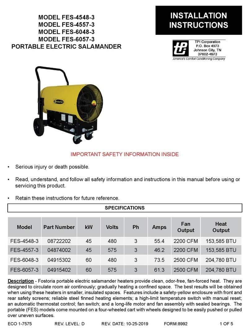
TPI Corporation FES-4548-3 User manual

TPI Corporation

TPI Corporation FES-4548-3 User manual

TPI Corporation AFA / 3320 Series User manual

TPI Corporation

TPI Corporation AFA / 3320 Series User manual

TPI Corporation Fostoria OCH Series User manual

TPI Corporation

TPI Corporation Fostoria OCH Series User manual

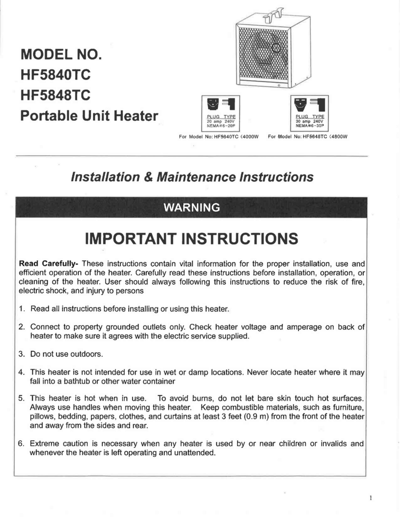
TPI Corporation HF5840TC Installation and operating instructions

TPI Corporation

TPI Corporation HF5840TC Installation and operating instructions

TPI Corporation 3900WW28 User manual

TPI Corporation

TPI Corporation 3900WW28 User manual

TPI Corporation 3200 Series User manual

TPI Corporation

TPI Corporation 3200 Series User manual

TPI Corporation 188T-ASA User manual

TPI Corporation

TPI Corporation 188T-ASA User manual

TPI Corporation Fostoria OCH2 Series User manual

TPI Corporation

TPI Corporation Fostoria OCH2 Series User manual

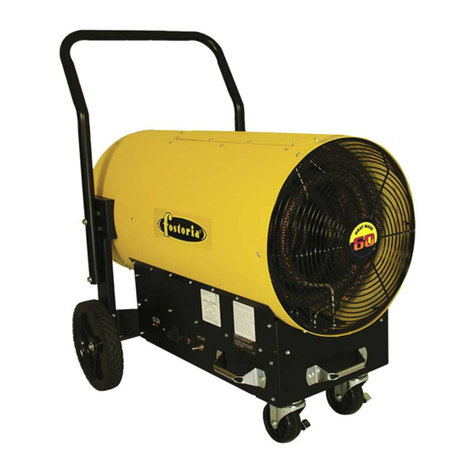
TPI Corporation FES-4548-3 User manual

TPI Corporation

TPI Corporation FES-4548-3 User manual

Popular Heater manuals by other brands

Ambient Air NDK15-12K instructions

Ambient Air

Ambient Air NDK15-12K instructions

Reznor OUH Series Installation and operating manual

Reznor

Reznor OUH Series Installation and operating manual

Delta HEX150PC instruction manual

Delta

Delta HEX150PC instruction manual

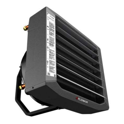
flowair ELiS C-W-100 Technical documentation operation manual

flowair

flowair ELiS C-W-100 Technical documentation operation manual

KEKAI KT2000 instruction manual

KEKAI

KEKAI KT2000 instruction manual

STIEBEL ELTRON CK 20 Premium Operation and installation instruction

STIEBEL ELTRON

STIEBEL ELTRON CK 20 Premium Operation and installation instruction

Cuisinart COH-500 manual

Cuisinart

Cuisinart COH-500 manual

Honeywell HZ-850 Series instructions

Honeywell

Honeywell HZ-850 Series instructions

L.B. White AW230 Owner's manual and instructions

L.B. White

L.B. White AW230 Owner's manual and instructions

for Living 043-5119-8 instruction manual

for Living

for Living 043-5119-8 instruction manual

UNITED UHM-874 user manual

UNITED

UNITED UHM-874 user manual

Better Bathrooms BeBa-25387 user manual

Better Bathrooms

Better Bathrooms BeBa-25387 user manual

Duraflame DFH-UH-5-T quick start guide

Duraflame

Duraflame DFH-UH-5-T quick start guide

Lasko 5521 operating manual

Lasko

Lasko 5521 operating manual

Nibe EAH 10 Installer manual

Nibe

Nibe EAH 10 Installer manual

DAY 69662 instruction manual

DAY

DAY 69662 instruction manual

Larson Electronics GAU-NFA-HH-150K instruction manual

Larson Electronics

Larson Electronics GAU-NFA-HH-150K instruction manual

Toyostove RSA-10 Operation and maintenance instructions

Toyostove

Toyostove RSA-10 Operation and maintenance instructions

manuals.online logo
manuals.online logoBrands
  • About & Mission
  • Contact us
  • Privacy Policy
  • Terms and Conditions

Copyright 2025 Manuals.Online. All Rights Reserved.