Table of Contents
P a g e |
i
Table of Contents
1.0
INTRODUCTION ......................................................................................................................................... 1
1.1
C
ONTACT
I
NFORMATION
........................................................................................................................................... 1
1.2
P
ARTS AND
S
ERVICE
I
NQUIRES
.................................................................................................................................... 1
1.3
T
ECHNICAL
S
PECIFICATIONS
....................................................................................................................................... 2
2.0
SAFETY ...................................................................................................................................................... 3
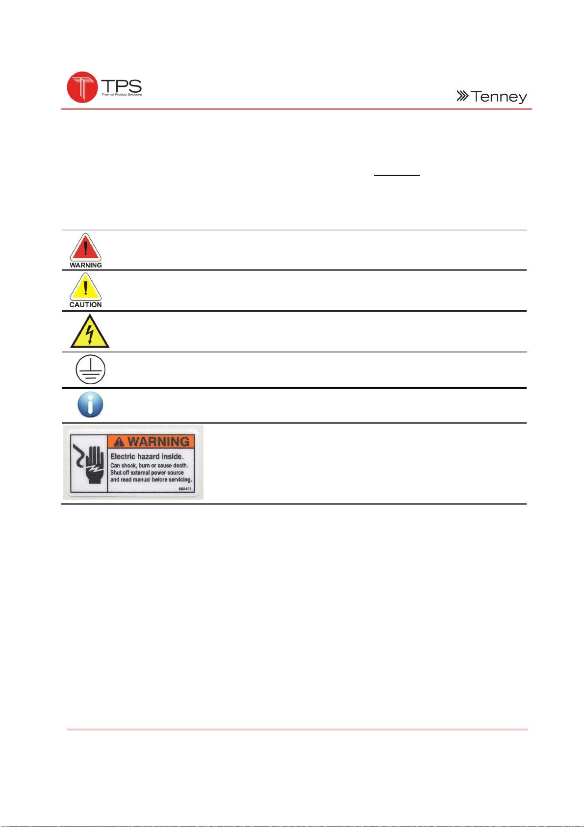
2.1
S
YMBOLS
............................................................................................................................................................... 3
2.2
W
ARNINGS
............................................................................................................................................................. 4
3.0
SYSTEM OVERVIEW .................................................................................................................................... 6
3.1
A
PPLICATION
.......................................................................................................................................................... 7
E
NVIRONMENTAL
C
ONDITIONING
F
UNCTIONS
....................................................................................................... 7
3.2
H
EATING
-A
LL
M
ODELS
............................................................................................................................................. 8
H
EATER
C
ONTROL
............................................................................................................................................ 8
3.3
C
OOLING
-A
LL
M
ODELS
.............................................................................................................................................
C
APILLARY
T
UBE
C
ONTROL
D
ESCRIPTION
............................................................................................................ 11
L
OW
S
TAGE
D
ESCRIPTION
............................................................................................................................... 11
H
IGH
S
TAGE
D
ESCRIPTION
............................................................................................................................... 11
R
EFRIGERANT
F
LOW
....................................................................................................................................... 11
3.4
S
AFETY
D
EVICES
.................................................................................................................................................... 11
L
OW
P
RESSURE
C
UT
-I
N
S
WITCH
PS2
AND
T
IMER
1TDR ....................................................................................... 11
H
IGH
P
RESSURE
C
UT
-I
N
S
WITCH
PS1 ................................................................................................................ 12
C
OMPRESSOR
M
OTOR
O
VERLOADS
................................................................................................................... 12
3.5
A
IR
C
IRCULATION
.................................................................................................................................................. 12
3.6
O
VER
T
EMPERATURE
P
ROTECTION
............................................................................................................................ 13
3.7
W
ATLOW
F4
T
EMPERATURE
C
ONTROLLER
................................................................................................................. 14
F
EATURES
.................................................................................................................................................... 14
D
ISPLAYS
..................................................................................................................................................... 14
I
NDICATOR
L
IGHTS
......................................................................................................................................... 14
K
EYS
........................................................................................................................................................... 15
D
ATA
C
OMMUNICATIONS
................................................................................................................................ 15
C
ONTROLLER
C
ONFIGURATION
......................................................................................................................... 15
4.0
OPTIONS ................................................................................................................................................. 16
4.1
B
OOST
H
EAT
........................................................................................................................................................ 16
4.2
D
RY
A
IR
P
URGE
S
YSTEM
......................................................................................................................................... 16
O
PERATION
.................................................................................................................................................. 16
D
RY
A
IR
E
QUIPMENT
D
ESCRIPTION
................................................................................................................... 16
4.3
GN
2
P
URGE
S
YSTEM
.............................................................................................................................................. 18
4.4
LN
2
B
OOST
C
OOLING
S
YSTEM
.................................................................................................................................. 1
O
PERATION
.................................................................................................................................................. 1