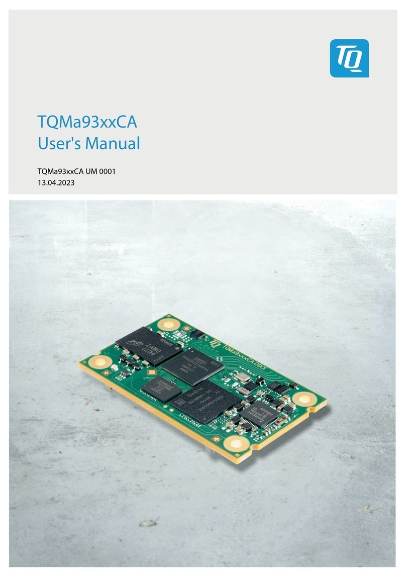
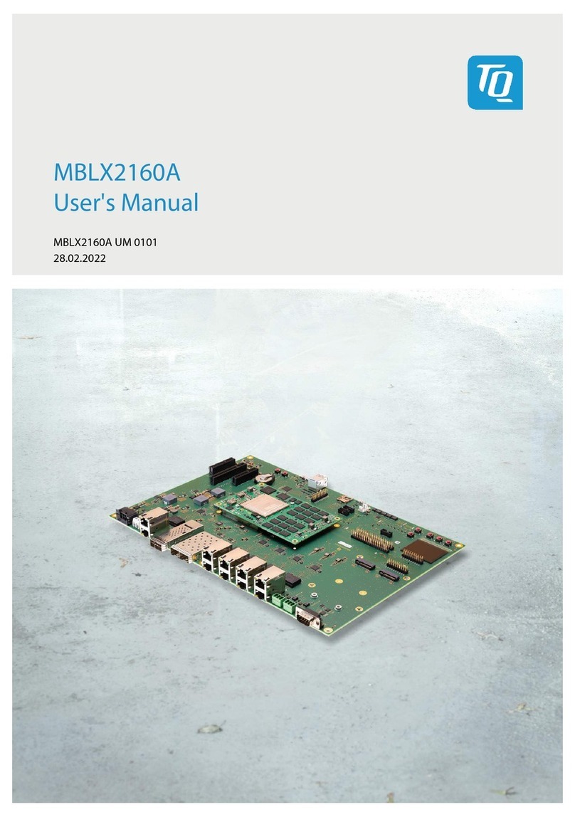
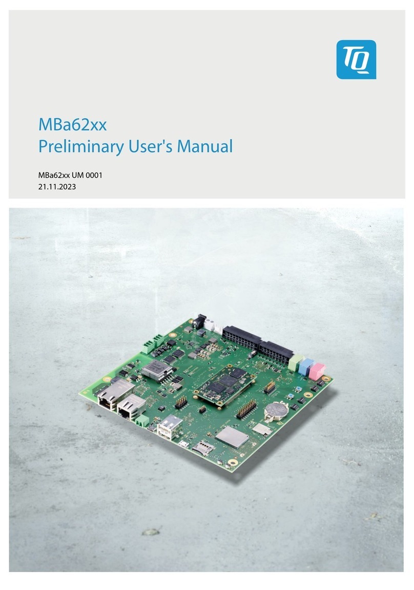
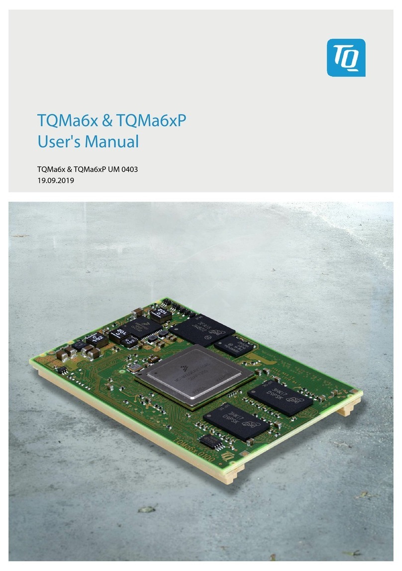
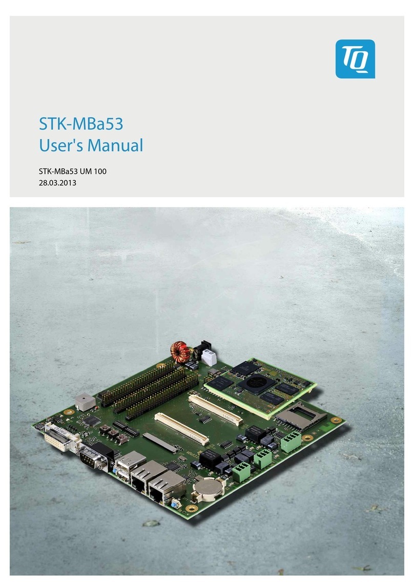
TQ-Systems STK-MBa28 User manual

STK-MBa28
User's Manual
STK-MBa28 UM 104
28.03.2013

User's Manual l STK-MBa28 UM 104 l © 2013 by TQ-Group
Pa e
i
Table of contents
1. ABOUT THIS MANUAL ...................................................................................................................... 1
1.1 Copyri ht and licence expenses ................................................................................................... 1
1.2 Re istered trademarks ..................................................................................................................... 1
1.3 Disclaimer ............................................................................................................................................ 1
1.4 Imprint .................................................................................................................................................. 1
1.5 Symbols and typo raphic conventions ..................................................................................... 2
1.6 Tips on safety ...................................................................................................................................... 3
1.7 Handlin and ESD tips ..................................................................................................................... 3
1.8 Namin of si nals .............................................................................................................................. 4
1.9 Further applicable documents / presumed knowled e ....................................................... 4
1.10 Acronyms and definitions ............................................................................................................... 5
2. BRIEF DESCRIPTION .......................................................................................................................... 7
3. TECHNICAL DATA .............................................................................................................................. 7
3.1 System architecture and system functionality ......................................................................... 7
3.1.1 Block dia ram ..................................................................................................................................... 7
3.1.2 Technical data electronics .............................................................................................................. 7
3.1.2.1 External interfaces ............................................................................................................................. 8
3.1.2.2 Internal interfaces ............................................................................................................................. 8
3.1.2.3 User's interfaces ................................................................................................................................. 8
3.1.2.4 System components ......................................................................................................................... 8
3.1.3 Technical data mechanics, desi n ............................................................................................... 8
4. ELECTRONICS SPECIFICATION ....................................................................................................... 9
4.1 External interfaces ............................................................................................................................. 9
4.1.1 Function specification ................................................................................................................... 10
4.1.1.1 Ethernet 1 (X26A) ............................................................................................................................ 10
4.1.1.2 Ethernet 2 (X26B) ............................................................................................................................. 11
4.1.1.3 RS485 (X32A) .................................................................................................................................... 11
4.1.1.4 RS232 (X32B) ..................................................................................................................................... 12
4.1.1.5 CAN 1/ CAN 2 (X1A) ........................................................................................................................ 12
4.1.1.6 GPIO (X1B) ......................................................................................................................................... 13
4.1.1.7 USB 2.0 Hi-Speed host (X12A) ..................................................................................................... 15
4.1.1.8 USB 2.0 Hi-Speed host (X12B) ...................................................................................................... 15
4.1.1.9 Audio output ri ht (X27) and left (X28), microphone input (X13) ................................... 16
4.1.1.10 SD card (X4) ....................................................................................................................................... 16
4.1.1.11 Power-In (X6) .................................................................................................................................... 16

User's Manual l STK-MBa28 UM 104 l © 2013 by TQ-Group
Pa e ii
Table of contents (continued)
4.1.2 Electrical characteristics ................................................................................................................ 17
4.1.2.1 Ethernet 1 (X26A) ............................................................................................................................ 17
4.1.2.2 Ethernet 2 (X26B) ............................................................................................................................. 17
4.1.2.3 RS485 (X32A) .................................................................................................................................... 17
4.1.2.4 RS232 (X32B) ..................................................................................................................................... 17
4.1.2.5 CAN 1/ CAN 2 (X1A) ........................................................................................................................ 17
4.1.2.6 GPIO (X1B) ......................................................................................................................................... 18
4.1.2.7 USB 2.0 Hi-Speed host (X12A) ..................................................................................................... 19
4.1.2.8 USB 2.0 Hi-Speed host (X12B) ...................................................................................................... 19
4.1.2.9 Audio output ri ht (X27) left (X28), microphone input (X13) ............................................ 19
4.1.2.10 SD card (X4) ....................................................................................................................................... 19
4.1.2.11 Power-In (X6) .................................................................................................................................... 20
4.1.3 Connectors and pin assi nments ............................................................................................... 21
4.1.3.1 Ethernet 1 / 2 (X26A/B) .................................................................................................................. 21
4.1.3.2 RS485 (X32A) .................................................................................................................................... 23
4.1.3.3 RS232 (X32B) ..................................................................................................................................... 24
4.1.3.4 CAN 1/ CAN 2 (X1A) ........................................................................................................................ 25
4.1.3.5 GPIO (X1B) ......................................................................................................................................... 26
4.1.3.6 USB 2.0 Hi-Speed host (X12A) ..................................................................................................... 27
4.1.3.7 USB 2.0 Hi-Speed host (X12B) ...................................................................................................... 28
4.1.3.8 Audio output ri ht (X27), left (X28) ........................................................................................... 29
4.1.3.9 Microphone input (X13) ................................................................................................................ 30
4.1.3.10 SD card (X4) ....................................................................................................................................... 31
4.1.3.11 Power-In (X6) .................................................................................................................................... 32
4.2 Internal interfaces ........................................................................................................................... 33
4.2.1 Function specification ................................................................................................................... 35
4.2.1.1 Module interfaces (X11, X17) ....................................................................................................... 35
4.2.1.2 JTAG (X16) ......................................................................................................................................... 35
4.2.1.3 LCD (X22, X23) .................................................................................................................................. 36
4.2.1.4 LCD backli ht (X5, X21, X24) ........................................................................................................ 37
4.2.1.5 Touchscreen (X2, X8, X20) ............................................................................................................ 38
4.2.1.6 LVDS display (X9) ............................................................................................................................. 39
4.2.1.7 Power-On (X19) ................................................................................................................................ 40
4.2.1.8 Accumulator connector (X7) ........................................................................................................ 40
4.2.1.9 Starterkit interfaces (X10, X14, X15)........................................................................................... 40

User's Manual l STK-MBa28 UM 104 l © 2013 by TQ-Group
Pa e
iii
Table of contents (continued)
4.2.2 Electrical characteristics ................................................................................................................ 41
4.2.2.1 Module interface (X11, X17) ......................................................................................................... 41
4.2.2.2 Power-On ........................................................................................................................................... 41
4.2.2.3 Accumulator connector (X7) ........................................................................................................ 41
4.2.2.4 JTAG (X16) ......................................................................................................................................... 41
4.2.2.5 LCD (X22, X23) .................................................................................................................................. 41
4.2.2.6 LCD backli ht (X5, X21, X24) ........................................................................................................ 42
4.2.2.6.1 Backli ht power supply (X5) ........................................................................................................ 42
4.2.2.6.2 LED driver (X21, X24) ...................................................................................................................... 42
4.2.2.7 Touchscreen (X2, X8, X20) ............................................................................................................ 42
4.2.2.8 LVDS display (X9) ............................................................................................................................. 42
4.2.2.9 Starterkit interfaces (X10, X14, X15)........................................................................................... 42
4.2.3 Connectors and pin assi nment ................................................................................................. 42
4.2.3.1 Receptacle for module................................................................................................................... 42
4.2.3.2 JTAG (X16) ......................................................................................................................................... 45
4.2.3.3 LCD (X22, X23) .................................................................................................................................. 45
4.2.3.4 LCD backli ht (X5, X21, X24) ........................................................................................................ 47
4.2.3.5 Touchscreen (X2, X8, X20) ............................................................................................................ 48
4.2.3.6 LVDS display (X9) ............................................................................................................................. 49
4.2.3.7 Power-On (X19) ................................................................................................................................ 50
4.2.3.8 Accumulator connector (X7) ........................................................................................................ 50
4.2.3.9 Starterkit interfaces (X10, X14, X15)........................................................................................... 51
4.2.3.9.1 Starterkit interface (X10) ............................................................................................................... 51
4.2.3.9.2 Starterkit interface (X14) ............................................................................................................... 52
4.2.3.9.3 Starterkit interface (X15) ............................................................................................................... 53
4.3 User's interfaces ............................................................................................................................... 54
4.3.1 Buzzer (N10) ...................................................................................................................................... 54
4.3.2 Reset push button (S2) .................................................................................................................. 54
4.3.3 Status-LEDs external (V77)............................................................................................................ 55
4.3.4 Status-LEDs internal (V22, V24, V25, V46) ................................................................................ 56
4.3.5 DIP switches (S1, S3, S4, S5) .......................................................................................................... 56
4.4 System components ....................................................................................................................... 58
4.4.1 Temperature sensor (D10) ............................................................................................................ 58
4.4.2 IC address allocation ..................................................................................................................... 58
4.4.3 Internal power supply .................................................................................................................... 58
4.4.4 Volta e supervision and reset ..................................................................................................... 59

User's Manual l STK-MBa28 UM 104 l © 2013 by TQ-Group
Pa e iv
Table of contents (continued)
5. SOFTWARE-SPECIFICATION .......................................................................................................... 59
6. MECHANICS SPECIFICATION ........................................................................................................ 60
6.1 Construction ..................................................................................................................................... 60
6.1.1 PCB outlines STK-MBa28 ............................................................................................................... 60
6.1.2 STK-MBa28 top view ....................................................................................................................... 61
6.1.3 STK-MBa28 bottom view ............................................................................................................... 62
6.2 Requirements for the superior system ..................................................................................... 63
6.2.1 Protection a ainst external effects ............................................................................................ 63
6.2.2 Thermal mana ement ................................................................................................................... 63
7. SAFETY REQUIREMENTS AND PROTECTIVE REGULATIONS ................................................ 64
7.1 EMC requirements .......................................................................................................................... 64
7.2 Operational safety and personal security ................................................................................ 64
8. CLIMATIC AND OPERATIONAL CONDITIONS .......................................................................... 65
8.1 Protection a ainst external effects ............................................................................................ 65
8.2 Reliability and product life ........................................................................................................... 65
8.3 Displays .............................................................................................................................................. 65
8.4 Environment protection ................................................................................................................ 66
8.5 RoHS compliance ............................................................................................................................ 66
8.6 WEEE re ulation .............................................................................................................................. 66
8.7 Accumulator ..................................................................................................................................... 66
9. APPENDIX .......................................................................................................................................... 67
9.1 References ......................................................................................................................................... 67

User's Manual l STK-MBa28 UM 104 l © 2013 by TQ-Group
Pa e
v
Table directory
Table 1: Terms and conventions ............................................................................................................. 2
Table 2: Acronyms ....................................................................................................................................... 5
Table 3: LAN8720A modes...................................................................................................................... 10
Table 4: Mappin of the GPIOs .............................................................................................................. 14
Table 5: Electrical characteristics of the GPIs .................................................................................... 18
Table 6: Electrical characteristics of the GPOs .................................................................................. 18
Table 7: Electrical characteristics of the power supply .................................................................. 20
Table 8: Overview of the function roups of the power supply ................................................. 20
Table 9: Ethernet connector 1/2 (X26A/B) ......................................................................................... 21
Table 10: Pin assi nment Ethernet 1/2 connectors (X26A/B) ........................................................ 21
Table 11: RS485 connector (X32A) ......................................................................................................... 23
Table 12: Pin assi nment RS485 connector (X32A) ........................................................................... 23
Table 13: RS232 connector (X32B) .......................................................................................................... 24
Table 14: Pin assi nment RS232 connector (X32B) ........................................................................... 24
Table 15: CAN 1 and CAN 2 connector (X1A) ...................................................................................... 25
Table 16: Pin assi nment CAN 1 and CAN 2 connector (X1A) ....................................................... 25
Table 17: GPIO connector (X1B) .............................................................................................................. 26
Table 18: Pin assi nment GPIO connector (X1B) ............................................................................... 26
Table 19: USB host connector (X12A) .................................................................................................... 27
Table 20: Pin assi nment USB host connector (X12A) ..................................................................... 27
Table 21: USB connector (X12B) .............................................................................................................. 28
Table 22: Pin assi nment USB host connector (X12B)...................................................................... 28
Table 23: Audio output ri ht (X27) and left (X28) .............................................................................. 29
Table 24: Pin assi nment audio output ri ht (X27) and left (X28) ............................................... 29
Table 25: Microphone connector (X13)................................................................................................. 30
Table 26: Pin assi nment microphone connector (X13) ................................................................. 30
Table 27: SD card connector (X4) ............................................................................................................ 31
Table 28: Pin assi nment SD card connector (X4) ............................................................................. 31
Table 29: Power-In connector (X6) ......................................................................................................... 32
Table 30: Pin assi nment power-in connector (X6) .......................................................................... 32
Table 31: LCD bus si nals (X22, X23) ..................................................................................................... 36
Table 32: Touchscreen connectors (X2, X8, X20) ............................................................................... 38
Table 33: Allocation of RGB si nals on LVDS lines ............................................................................. 39
Table 34: Receptacle for module............................................................................................................. 42
Table 35: Pin assi nment STK-MBa28 – TQMa28 (X17 – (X1)) ........................................................ 43
Table 36: Pin assi nment STK-MBa28 – TQMa28 (X11 – (X2)) ........................................................ 44
Table 37: JTAG connector (X16) .............................................................................................................. 45

User's Manual l STK-MBa28 UM 104 l © 2013 by TQ-Group
Pa e vi
Table directory (continued)
Table 38: Pin assi nment JTAG connector (X16) ................................................................................ 45
Table 39: LCD connectors (X22, X23) ..................................................................................................... 45
Table 40: Pin assi nment LCD connectors (X22, X23) ...................................................................... 46
Table 41: LCD backli ht connector (X5) ................................................................................................ 47
Table 42: Pin assi nment LCD backli ht connector (X5) ................................................................. 47
Table 43: LCD backli ht connectors (X21, X24) .................................................................................. 47
Table 44: Pin assi nment LCD backli ht connectors (X21, X24) ................................................... 47
Table 45: Touchscreen connector (X2) .................................................................................................. 48
Table 46: Pin assi nment touchscreen connector (X2) .................................................................... 48
Table 47: Touchscreen connector (X8) .................................................................................................. 48
Table 48: Touchscreen connector (X20) ............................................................................................... 48
Table 49: Pin assi nment touchscreen connectors (X8, X20) ........................................................ 48
Table 50: LVDS display connector (X9) .................................................................................................. 49
Table 51: Pin assi nment LVDS display connector (X9) ................................................................... 49
Table 52: Power-On connector (X19) ..................................................................................................... 50
Table 53: Pin assi nment power-on connector (X19) ...................................................................... 50
Table 54: Accumulator connector (X7) .................................................................................................. 50
Table 55: Pin assi nment accumulator connector (X7) ................................................................... 50
Table 56: Starterkit interface connector (X10) .................................................................................... 51
Table 57: Pin assi nment Starterkit interface connector (X10) ..................................................... 51
Table 58: Starterkit interface connector (X14) .................................................................................... 52
Table 59: Pin assi nment Starterkit interface connector (X14) ..................................................... 52
Table 60: Starterkit interface connector (X15) .................................................................................... 53
Table 61: Pin assi nment Starterkit interface connector (X15) ..................................................... 53
Table 62: Reset push button (S2) ............................................................................................................ 54
Table 63: External status LEDs (V77) ...................................................................................................... 55
Table 64: Overview external LEDs ........................................................................................................... 55
Table 65: Overview internal LEDs ........................................................................................................... 56
Table 66: DIP switch S1 .............................................................................................................................. 56
Table 67: DIP switch S3 .............................................................................................................................. 56
Table 68: DIP switch S4 .............................................................................................................................. 57
Table 69: DIP switch S5 .............................................................................................................................. 57
Table 70: Boot mode options ................................................................................................................... 57
Table 71: IC address allocation ............................................................................................................... 58
Table 72: Internal power supply .............................................................................................................. 58
Table 73: Reset tri er level and volta e supervision ...................................................................... 59
Table 74: Further applicable documents .............................................................................................. 67

User's Manual l STK-MBa28 UM 104 l © 2013 by TQ-Group
Pa e
vii
Illustration directory
Illustration 1: STK-MBa28 block dia ram ............................................................................................ 7
Illustration 2: External interfaces of the STK-MBa28 ........................................................................ 9
Illustration 3: Ethernet 1, block dia ram ........................................................................................... 10
Illustration 4: Ethernet 2, block dia ram ........................................................................................... 11
Illustration 5: RS485 block dia ram .................................................................................................... 11
Illustration 6: RS232 block dia ram .................................................................................................... 12
Illustration 7: CAN block dia ram ........................................................................................................ 12
Illustration 8: GPIO block dia ram ....................................................................................................... 13
Illustration 9: USB host block dia ram ............................................................................................... 15
Illustration 10: USB OTG block dia ram ............................................................................................... 15
Illustration 11: Audio block dia ram ..................................................................................................... 16
Illustration 12: SD card block dia ram ................................................................................................. 16
Illustration 13: Power-In block dia ram ............................................................................................... 16
Illustration 14: Wirin of connector X26 .............................................................................................. 22
Illustration 15: Wirin of connector X32A ........................................................................................... 23
Illustration 16: Wirin of connector X32B............................................................................................ 24
Illustration 17: Wirin of connector X1A .............................................................................................. 25
Illustration 18: Wirin of connector X1B .............................................................................................. 26
Illustration 19: Wirin of connector X12A ........................................................................................... 27
Illustration 20: Wirin of connector X12B............................................................................................ 28
Illustration 21: Wirin of connectors X27 and X28 ........................................................................... 29
Illustration 22: Wirin of connector X13 .............................................................................................. 30
Illustration 23: Wirin of connector X4................................................................................................. 31
Illustration 24: Wirin of connector X6................................................................................................. 32
Illustration 25: Internal and external interfaces top side ................................................................ 33
Illustration 26: Internal and external interfaces bottom side ........................................................ 34
Illustration 27: LCD block dia ram ........................................................................................................ 36
Illustration 28: LCD backli ht block dia ram ..................................................................................... 37
Illustration 29: Touchscreen block dia ram ....................................................................................... 38
Illustration 30: LVDS display block dia ram ....................................................................................... 39
Illustration 31: Power-On block dia ram ............................................................................................. 40
Illustration 32: Pinout of connectors X21, X24 ................................................................................... 47
Illustration 33: Buzzer block dia ram ................................................................................................... 54
Illustration 34: LED block dia ram ......................................................................................................... 55
Illustration 35: Internal power supply block dia ram ...................................................................... 58
Illustration 36: Volta e supervision / reset block dia ram ............................................................. 59
Illustration 37: PCB outlines STK-MBa28 .............................................................................................. 60
Illustration 38: STK-MBa28 top view ..................................................................................................... 61
Illustration 39: STK-MBa28 bottom view ............................................................................................. 62

User's Manual l STK-MBa28 UM 104 l © 2013 by TQ-Group
Pa e viii
Revision history
Rev.
Date Name
Pos. Modification
100 23.05.2011
Petz Document created
101 14.07.2011
Petz Illustration 34
Table 33
Table 35
Replaced
Order code revised
Pin assi nment revised
102 11.11.2011
Petz All Completely revised
103 24.05.2012
Petz Table 36
Table 36
Section 5
Typo corrected: LDADC4 LRADC4
Ne ation removed: USB_0_PWR_EN, USB_1_PWR_EN
Link to Wiki added
104 28.03.2013
Petz 4.1.1.1
All
Info concernin pull-up and pull-down resistors added
Si nal description of SD_WP and SD_DETECT#
corrected

User's Manual l STK-MBa28 UM 104 l © 2013 by TQ-Group
Pa e
1
1.
1.1.
1. ABOUT THIS MANUAL
ABOUT THIS MANUALABOUT THIS MANUAL
ABOUT THIS MANUAL
1.1
1.11.1
1.1 Copyri ht and licence expenses
Copyri ht and licence expensesCopyri ht and licence expenses
Copyri ht and licence expenses
Copyri ht protected © 2013 by TQ-Systems GmbH. This User’s Manual may not be copied,
reproduced, translated, chan ed or distributed, completely or partially in electronic, machine
readable, or in any other form without the written consent of TQ-Systems GmbH. The drivers
and utilities for the used components as well as the BIOS are subject to the copyri hts of the
respective manufacturers. The licence conditions of the respective manufacturer are to be
adhered to. Bootloader-licence expenses are paid by TQ-Systems and are included in the price.
Licence expenses for the operatin system and applications are not taken into consideration and
must be separately calculated / declared.
1.2
1.21.2
1.2 Re istered trademarks
Re istered trademarksRe istered trademarks
Re istered trademarks
TQ-Systems GmbH aims to adhere to the copyri hts of all the raphics and texts used in all
publications, and strives to use ori inal or license-free raphics and texts. All the brand names
and trademarks mentioned in the publication, includin those protected by a third party, unless
specified otherwise in writin , are subjected to the specifications of the current copyri ht laws
and the proprietary laws of the present re istered proprietor without any limitation. One should
conclude that brand and trademarks are ri htly protected by of a third party.
1.3
1.31.3
1.3 Disclaimer
DisclaimerDisclaimer
Disclaimer
TQ-Systems GmbH does not uarantee that the information in this manual is up-to-date, correct,
complete or of ood quality. Nor does TQ-Systems assume uarantee for further usa e of the
information. Liability claims a ainst TQ-Systems GmbH, referrin to material or non-material
related dama es caused, due to usa e or non-usa e of the information iven in the manual,
or due to usa e of erroneous or incomplete information, are exempted, as lon as there is no
proven intentional or ne li ent fault of TQ-Systems GmbH. TQ-Systems GmbH explicitly reserves
the ri hts to chan e or add to the contents of this manual or parts of it without special
notification.
1.4
1.41.4
1.4 Imprint
ImprintImprint
Imprint
TQ-Systems GmbH
Gut Dellin , Mühlstraße 2
82229 Seefeld
Tel: +49 (0) 8153 9308–0
Fax: +49 (0) 8153 9308–134
Web: http://www.tq- roup.com/

User's Manual l STK-MBa28 UM 104 l © 2013 by TQ-Group
Pa e 2
1.5
1.51.5
1.5 Symbols and typo raphic conventions
Symbols and typo raphic conventionsSymbols and typo raphic conventions
Symbols and typo raphic conventions
Table 1: Terms and conventions
Symbol Meanin
This symbol represents the handlin of electrostatic-sensitive modules and
/ or components. These components are often dama ed / destroyed by the
transmission of a volta e hi her than about 50 V.
A human body usually only experiences electrostatic dischar es above
approximately 3,000 V.
This symbol indicates the possible use of volta es hi her than 24 V.
Please note the relevant statutory re ulations in this re ard.
Non-compliance with these re ulations can lead to serious dama e to your
health and also cause dama e / destruction of the component.
This symbol indicates a possible source of dan er. Actin a ainst the
procedure described can lead to possible dama e to your health and / or
cause dama e / destruction of the material used.
This symbol represents important details or aspects for workin with TQ-
products.
Command
A font with fixed-width is used to denote commands, file names, or menu
items.

User's Manual l STK-MBa28 UM 104 l © 2013 by TQ-Group
Pa e
3
1.6
1.61.6
1.6 Tips on safety
Tips on safetyTips on safety
Tips on safety
Improper or incorrect handlin of the product can substantially reduce its life span.
1.7
1.71.7
1.7 Handlin and ESD tips
Handlin and ESD tipsHandlin and ESD tips
Handlin and ESD tips
General handlin of your TQ-products
The TQ-product may only be used and serviced by certified personnel who
have taken note of the information, the safety re ulations in this document
and all related rules and re ulations.
A eneral rule is: do not touch the TQ-product durin operation. This is
especially important when switchin on, chan in jumper settin s or
connectin other devices without ensurin beforehand that the power
supply of the system has been switched off.
Violation of this uideline may result in dama e / destruction of the module
and be dan erous to your health.
Improper handlin of your TQ-product would render the uarantee invalid.
Proper ESD handlin
The electronic components of your TQ-product are sensitive to electrostatic
dischar e (ESD).
Always wear antistatic clothin , use ESD-safe tools, packin materials etc.,
and operate your TQ-product in an ESD-safe environment. Especially when
you switch modules on, chan e jumper settin s, or connect other devices.

User's Manual l STK-MBa28 UM 104 l © 2013 by TQ-Group
Pa e 4
1.8
1.81.8
1.8 Namin of si nals
Namin of si nalsNamin of si nals
Namin of si nals
A hash mark (#) at the end of the si nal name indicates a low-active si nal.
Example: RESET#
If a si nal can switch between two functions and if this is noted in the name of the si nal, the
low-active function is marked with a hash mark # and shown at the end.
Example: C / D#
If a si nal has multiple functions, the individual functions are separated by slashes when they are
important for the wirin .
The identification of the individual functions follows the above conventions.
Example: WE2# / OE#
1.9
1.91.9
1.9 Further applicable documents / presumed knowled e
Further applicable documents / presumed knowled eFurther applicable documents / presumed knowled e
Further applicable documents / presumed knowled e
•Specifications and manual of the used modules:
Specifications and manual of the used modules: Specifications and manual of the used modules:
Specifications and manual of the used modules:
These documents describe the service, functionality and special characteristics of the
used module (incl. BIOS).
•Specifications of the used components:
Specifications of the used components: Specifications of the used components:
Specifications of the used components:
The manufacturer's specifications of the used components, for example CompactFlash
cards, are to be taken note of.
They contain, if applicable, additional information that must be taken note of for safe
and reliable operation.
These documents are stored at TQ-Systems.
•Chip errata:
Chip errata: Chip errata:
Chip errata:
It is the user's responsibility to make sure all errata published by the manufacturer of
each component are taken note of.
The manufacturer’s advice should be followed.
•Software behaviou
Software behaviouSoftware behaviou
Software behaviour:
r: r:
r:
No warranty can be iven, nor responsibility taken for any unexpected software
behaviour due to deficient components.
•General expertise:
General expertise: General expertise:
General expertise:
Expertise in electrical en ineerin / computer en ineerin is required for the
installation and the use of the device.

User's Manual l STK-MBa28 UM 104 l © 2013 by TQ-Group
Pa e
5
1.10
1.101.10
1.10 Acronyms and definitions
Acronyms and definitionsAcronyms and definitions
Acronyms and definitions
The followin acronyms and abbreviations are used in this document:
Table 2: Acronyms
Acronym
Meanin
AC Alternatin Current
AD Address/Data
AD Air Dischar e
ADC Analo /Di ital Converter
ARM® Advanced RISC Machine
BIOS Basic Input/Output System
CAN Controller Area Network
CD Card Detect
CD Contact Dischar e
CPU Central Processin Unit
DC Direct Current
DIN Deutsche Industrie Norm
DIP Dual In-line Packa e
DUART Dual Universal Asynchronous Receiver/Transmitter
EEPROM Electrically Erasable Pro rammable Read-Only Memory (Byte-wise re-writable)
EGB Elektrostatisch Gefährdete Bauelemente
EMC Electroma netic Compatibility
eMMC Embedded MultiMediaCard (Flash)
EN Europäische Norm
ESD Electrostatic Dischar e
FET Field Effect Transistor
FFC Flat Flex Cable
GPI General Purpose Input
GPIO General Purpose Input/Output
GPO General Purpose Output
I/O Input/Output
I/P Input/Power
IEEE Institute of Electrical and Electronics En ineers
IP00 In ress Protection 00
IC Inter-Inte rated Circuit
IS Inter Inte rated Circuit Sound
JTAG Joint Test Action Group

User's Manual l STK-MBa28 UM 104 l © 2013 by TQ-Group
Pa e 6
Table 2: Acronyms (continued)
Acronym
Meanin
LCD Liquid Crystal Display
LED Li ht Emittin Diode
LS Low Speed (USB: 1.5 Mbit/s)
LSB Least Si nificant Bit
LVDS Low Volta e Differential Si nal
MMC Multimedia Card
MOZI Module extractor (Modulzieher)
NC Not Connected
O/P Output/Power
OTG On-The-Go
PCB Printed Circuit Board
PD Pull-Down (Resistor)
PHY Physical (Interface)
PU Pull-Up (Resistor)
PWM Pulse Width Modulation
RCA Radio Corporation of America
RFU Reserved for Future Use
RGB Red Green Blue
RJ Re istered Jack
RS232 Recommended Standard (serielle Schnittstelle)
RTC Real-Time Clock
RoHS Restriction of (the use of certain) Hazardous Substances
SD Secure Di ital
SDHC Secure Di ital Hi h Capacity
SPDIF Sony-Philips Di ital Interface Format
SPS Speicherpro rammierbare Steuerun Pro rammable Lo ic Controller (PLC)
STK Starterkit
THD+N Total Harmonic Distortion + Noise
UART Universal Asynchronous Receiver/Transmitter
USB Universal Serial Bus
VGA Video Graphics Array (640 × 480)
WEEE Waste Electrical and Electronic Equipment
WP Write-Protect

User's Manual l STK-MBa28 UM 104 l © 2013 by TQ-Group
Pa e
7
2.
2.2.
2. BRIEF DESCRIPTION
BRIEF DESCRIPTIONBRIEF DESCRIPTION
BRIEF DESCRIPTION
The STK-MBa28 is desi ned to be driven by the TQ-module TQMa28, which is based on the
Freescale ARM-CPU MCIMX287 (i.MX28). In combination with a module and a display with
touchscreen it offers PC core functionalities and standard interfaces.
By usin the functionalities of the Starterkit STK-MBa28 this carrier board forms to ether with the
TQMa28 a modular system to develop own product ideas.
3.
3.3.
3. TECHNICAL DATA
TECHNICAL DATATECHNICAL DATA
TECHNICAL DATA
3.1
3.13.1
3.1 System architecture an
System architecture anSystem architecture an
System architecture and system functionality
d system functionalityd system functionality
d system functionality
3.1.1 Block dia ram
TQMa28
Ethernet
transceiver
LAN8720A
2 x CAN
D-sub 9-pin
USB Host
type A
(OTG capable)
SD card
24 V GPIORS485
80-pin plug connector
tyco 5177986-3
80-pin plug connector
tyco 5177986-3
USB Host
type A
RS232Ethernet 1
High-Side
VN808CM-E
I²C
expander
PCA9554
RS232
SP3222E
RS485
SP491E
CAN
transceiver
MCP2551
Audio codec
SGTL5000
Buzzer
HP / Line out
2 x Cinch (stereo)
Microphone
3.5 mm phone jack LCD LVDS
connector
Backlight
driver
LT3518
LED
backlight
External lithium
accumulator
Temperature
sensor
LM73CIMK-0
LVDS
transmitter
SN75LVDS83B
Opto
coupler
LCD_Bus
I2C 1
VCC_BATTERY
Touch
Ethernet 2
RJ45
SD_Card
I2S
CAN 0
CAN 1
Ethernet
Ethernet
Opto
coupler
driver
Opto
coupler
D-sub 9-pin D-sub 9-pin D-sub 15-pin
transceiver transceiver
JTAG
Boot
configuration
LRADC
I2C 1
Internal
expansion
connector 1
Internal
expansion
connector 3
Internal
expansion
connector 2
UART 0
UART 3
RJ45
CAN
transceiver
MCP2551
Ethernet
transceiver
LAN8720A
I2C 1
I2C 1
I²C
expander
PCA9554
Illustration 1: STK-MBa28 block dia ram
3.1.2 Technical data electronics
The interfaces and system components listed in the followin are implemented on the
STK-MBa28. Due to the fact that the STK-MBa28 can be installed in a casin the interfaces are
divided into external and internal interfaces.

User's Manual l STK-MBa28 UM 104 l © 2013 by TQ-Group
Pa e 8
3.1.2.1 External interfaces
•2 × Ethernet 10/100 Mbit
•1 × RS485
•1 × RS232
•2 × CAN
•1 × USB 2.0 Hi-Speed host interface
•1 × USB 2.0 Hi- Speed host interface (On-the-Go capable)
•1 × GPIO (8 × OUT / 4 × IN)
•1 × SD card
•2 × Audio output
•1 × Microphone input
•1 × Power supply
3.1.2.2 Internal interfaces
•1 × TQMa28
•1 × JTAG
•2 × LCD (model dependent)
•2 × LCD backli ht (model dependent)
•3 × touchscreen (model dependent)
•1 × LCD via LVDS (optional)
•1 × Power-On push button
•3 × Headers for specific extensions
•Connector for accumulator
3.1.2.3 User's interfaces
•1 × Reset push button
•3 × Status LED (external) User-LED 1, User-LED 2, Power-LED
•4 × Status LED (internal) Reset-LED, USB_OC-LED 1, USB_OC-LED 2, front Power-LED
•4 × DIP switch
•Buzzer
3.1.2.4 System components
•Temperature sensor
•Internal power supply
•Volta e supervision and reset concept
•IC bus
3.1.3 Technical data mechanics, desi n
Dimensions PCB (W × D × H): 175 × 120 × 2 mm
Overall dimensions (W × D × H): 175 × 130 × 32 mm (app.)
Wei ht: 248

User's Manual l STK-MBa28 UM 104 l © 2013 by TQ-Group
Pa e
9
4.
4.4.
4. ELECTRONICS SPECIFIC
ELECTRONICS SPECIFICELECTRONICS SPECIFIC
ELECTRONICS SPECIFICATION
ATIONATION
ATION
4.1
4.14.1
4.1 External interfaces
External interfacesExternal interfaces
External interfaces
Illustration 2: External interfaces of the STK-MBa28

User's Manual l STK-MBa28 UM 104 l © 2013 by TQ-Group
Pa e 10
4.1.1 Function specification
4.1.1.1 Ethernet 1 (X26A)
The TQMa28 directly drives the Ethernet 1 interface. The SMSC LAN8720A is used as PHY.
IEEE1588 frames are supported. The 1588-si nals are accessible at connector X10
(see 4.2.3.9.1).
TQMa28 - X2
ENET0_TXD0
ENET0_TXD1
LAN8720A
TXD0
TXD1
RST#
ENET0_TX_EN TXEN
ENET0_RXD0 RXD0/MODE0
ENET0_RXD1 RXD1/MODE1
ENET0_RX_EN CRS_DV/MODE2
CLKIN
ENET_CLK
ENET_FEC_RESET_B#
LED1
LED2#
MBa28 – X26A
RJ45
LED
LED
TX
RX
ENET_MDIO
ENET_MDC MDC
MDIO 10 k
3.3 V
PHYAD0
Illustration 3: Ethernet 1, block dia ram
The LAN8720A offers the followin modes:
Table 3: LAN8720A modes
Mode
[0…2] Function Remark
000 10BASE-T Half-duplex, autone otiation off
001 10BASE-T Full-duplex, autone otiation off
010 10BASE-TX Half-duplex, autone otiation off
011 100BASE-TX Full-duplex, autone otiation off
100 100BASE-TX Half-duplex start, autone otiation on
101 100BASE-TX Repeater mode, half-duplex start, autone otiation on
110 Power down Information in data sheet
111
111111
111
ALL capable
ALL capableALL capable
ALL capable
No determination, autone otiation on,
No determination, autone otiation on, No determination, autone otiation on,
No determination, autone otiation on,
mode is preset in hardware
mode is preset in hardwaremode is preset in hardware
mode is preset in hardware
This table does not replace the data sheet of the LAN8720A.
Suitable 10 kΩ pull-up or pull-down resistors at the mode pins have to be placed on the carrier
board.

User's Manual l STK-MBa28 UM 104 l © 2013 by TQ-Group
Pa e
11
4.1.1.2 Ethernet 2 (X26B)
The TQMa28 directly drives the Ethernet 2 interface. The SMSC LAN8720A is used as PHY.
TQMa28 - X2
ENET1_TXD0
ENET1_TXD1
LAN8720A
TXD0
TXD1
RST#
ENET1_TX_EN TXEN
ENET1_RXD0 RXD0/MODE0
ENET1_RXD1 RXD1/MODE1
ENET1_RX_EN CRS_DV/MODE2
CLKIN
ENET_CLK
ENET_FEC_RESET_B#
LED1
LED2#
MBa28 – X26A
RJ45
LED
LED
TX
RX
ENET_MDIO
ENET_MDC MDC
MDIO
10 kPHYAD0
Illustration 4: Ethernet 2, block dia ram
4.1.1.3 RS485 (X32A)
The AUART0 of the TQMa28 drives the RS485 interface of the STK-MBa28. The optocouplers
Ava o HCPL0631 and HCPL0601 are used for alvanic separation. The Recom RSS-0505/HP
serves as the power supply for the alvanically separated part of the RS485 interface.
The Exar SP491EEN-L is used as RS485 transceiver.
120 R
galvanic
separation SP491E MBa28 – X32A
D-Sub 9
Y/Z
A/B
TQMa28 - X1
AUART0_RTS
AUART0_RxD
AUART0_TxD
S3-4
S3-3
120 R
HCPL0631
HCPL0601
RSS-0505/HP
DE
DI
RO
RE#
n.a.
Illustration 5: RS485 block dia ram
The RS485 si nals can be terminated with 120 Ω with either DIP switch S3 or cable-sided by
brid in pins 8 / 9 (RxD) and 1 / 7 (TxD). Details can be found in Table 67 on pa e 56.
Table of contents
Other TQ-Systems Computer Hardware manuals
Popular Computer Hardware manuals by other brands

Spectra Engineering
Spectra Engineering RELM BK Radio MX800 T19 Technical manual

Leviton
Leviton 47693-3BY installation instructions

Intelligent Motion Systems
Intelligent Motion Systems MDrive DSP-402 Application guide

Supermicro
Supermicro X11SDC-4C user manual

Onkyo
Onkyo ES-600PRO Service manual

Adaptec
Adaptec PowerDomain 29160 manual

Aqua Computer
Aqua Computer RGBpx Splitty12 ACTIVE instruction manual

Pinnacle
Pinnacle PCTV 7010IX user manual

ADTRAN
ADTRAN ESU 120e quick start guide

Moxa Technologies
Moxa Technologies RKP-A110 Series user manual

Marvell
Marvell 88MW300 Technical Product Documentation

Renesas
Renesas QB-MINI2-RF Setup guide