TQC SP7316 User manual

1 |
PRETREATMENT TEST KIT
SP7316

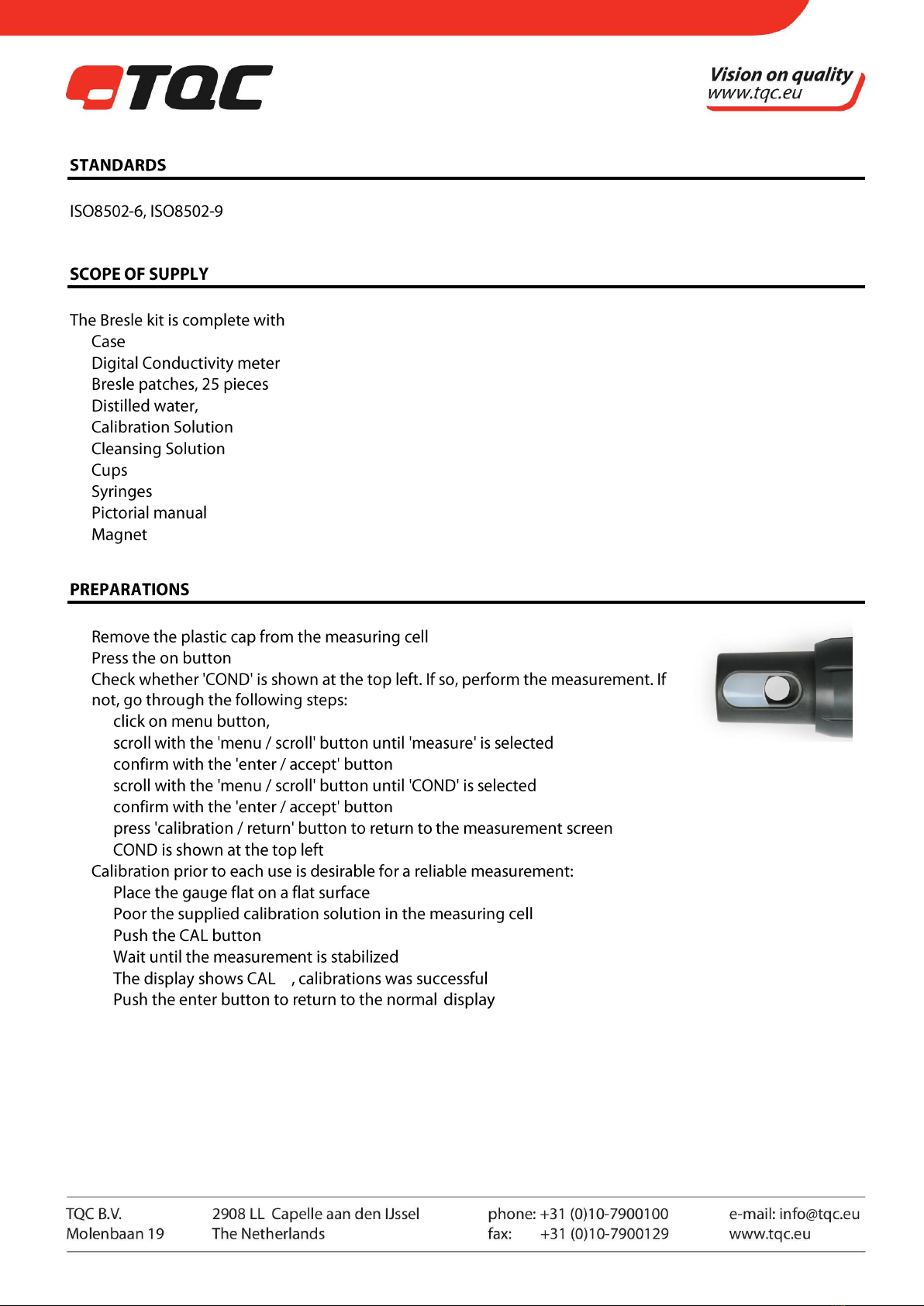
Measuring Cell


1 |
DUST TEST KIT
SP3200
DISCLAIMER
The right of technical
modifications is reserved.
The information given in this
manual is not intended to be
exhaustive and any person
using the product for any
purpose other than that
specifically recommended in
this manual without first
obtaining written
confirmation from us as to
the suitability of the product
for the intended purpose
does so at his own risk.
Whilst we endeavour to
ensure that all advice we
give about the product
(whether in this manual or
otherwise) is correct we
have no control over either
the quality or condition of
the product or the many
factors affecting the use and
application of the product.
Therefore, unless we
specifically agree in writing
to do so, we do not accept
any liability whatsoever or
howsoever arising for the
performance of the product
or for any loss or damage
(other than death or
personal injury resulting
from our negligence) arising
out of the use of the
product. The information
contained in this manual is
liable to modification from
time to time in the light of
experience and our policy of
continuous product
development.

1 |
SPRING LOADED ROLLER FOR DUST TEST TAPE
SP3600
1SAFETY PRECAUTIONS
•Always keep the instrument in its case when not in use.
•Though robust in design, this instrument is precision-machined. Never drop it
or knock it over
•Clean the instrument with a damp soft cloth. Never use abrasives or solvents.
2PRODUCT DESCRIPTION
The Spring Loaded Roller is used to perform objective dust tape tests, as mentioned in ISO 8502-3, and
eliminates the human factor. The Spring loaded roller is so designed that it is capable of applying a load of 44,13
N. Iso 8502-3 quantifies the quantity and size of dust particles on surfaces prepared for painting. This test has to
be performed just before the paint is applied. The test itself is not included in the delivery
3STANDARDS
ISO 8502-3, IMO-PSPC MSC.215(82) and MSC.244(83)
4WHAT’S IN THE BOX?
TQC Spring Loaded Roller
Plastic carrying case
Calibration certificate
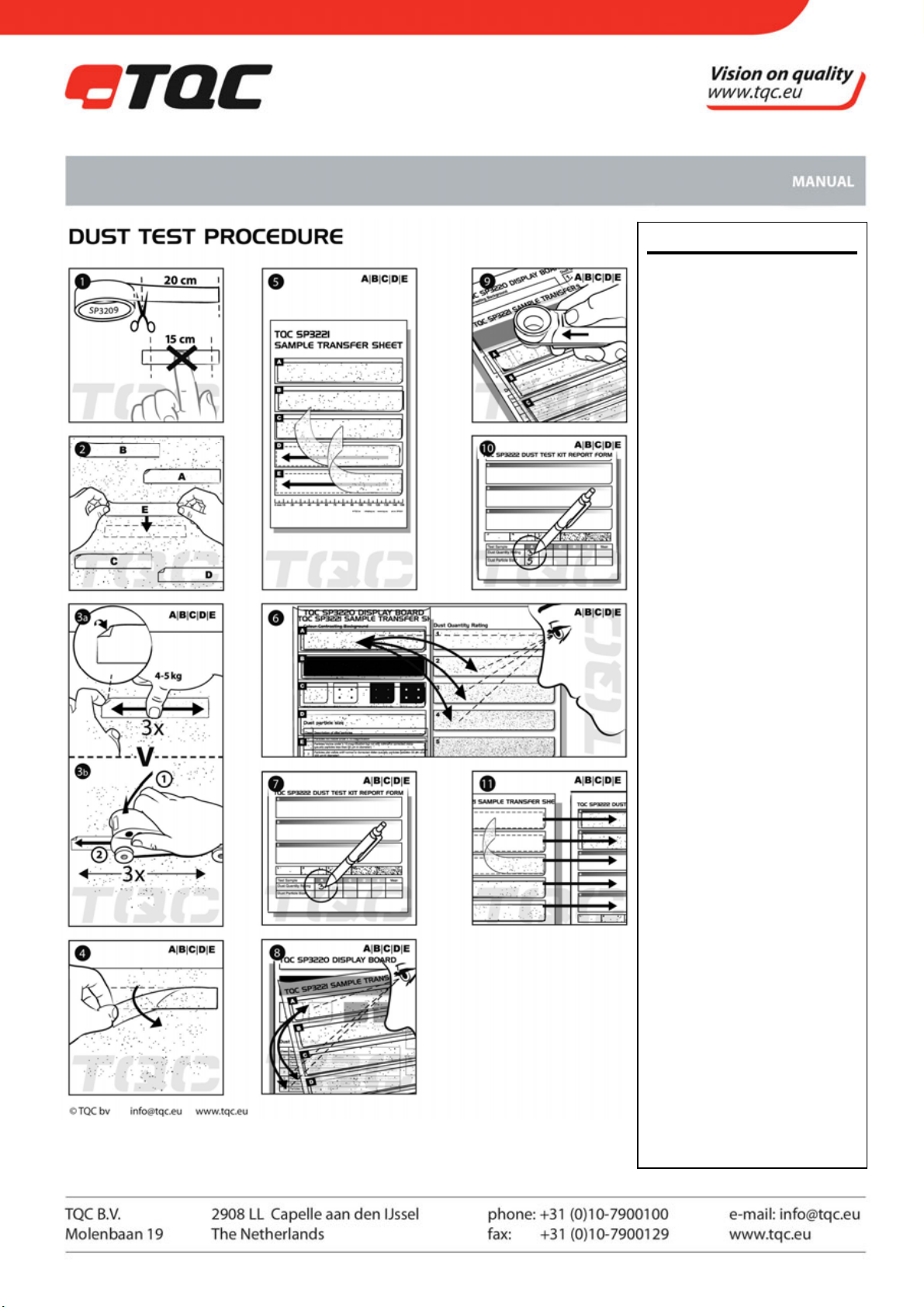
5PERFORM A MEASUREMENT
•Cut a piece of 20 cm from the special specified dust tape(SP3209) supplied with the Dust Test Kit SP3200 or
the PreTreatment Kit SP7315/7316.
•Apply the tape at an appropriate location and rub 3 times by thumb with a hand force of approx. 4-5 kg.
•Take the Spring Loaded Roller and place it axial over the applied tape before.
•Press and hold down the roller till all wheels are in contact with the surface to assure the specified force of
44,13 N is applied.
•Move the spring roller, while holding it down, 3 times for and backwards over the tape.
•Peel the tape off by taking it on one of the corners and apply it on a Sample Transfer Sheet (SP3221) to
examine and rate.

2 |
6MAINTENANCE
•Though robust in design, this instrument is precision-machined. Never drop it or knock it over
•Always clean the instrument after use.
•Clean the instrument using a soft dry cloth. Never clean the instrument by any mechanical means such as a
wire brush or abrasive paper. This may cause, just like the use of aggressive cleaning agents, permanent
damage.
•Always keep the instrument in its case when not in use.
7DISCLAIMER
The right of technical modifications is reserved.
The information given in this manual is not intended to be exhaustive and any person using the product for any
purpose other than that specifically recommended in this manual without first obtaining written confirmation
from us as to the suitability of the product for the intended purpose does so at his own risk. Whilst we
endeavour to ensure that all advice we give about the product (whether in this manual or otherwise) is correct
we have no control over either the quality or condition of the product or the many factors affecting the use and
application of the product. Therefore, unless we specifically agree in writing to do so, we do not accept any
liability whatsoever or howsoever arising for the performance of the product or for any loss or damage (other
than death or personal injury resulting from our negligence) arising out of the use of the product. The
information contained in this manual is liable to modification from time to time in the light of experience and
our policy of continuous product development.

1|
TQC SURFACE PROFILE AND COATING THICKNESS GAUGE
SP1560
1PRODUCT DESCRIPTION
The TQC Surface Profile & Coating Thickness gauge is a combination gauge. that can be
equipped with two different tips, one for surface roughness and another for coating
thickness.
1.1 Technical Specifications
Range : 0~3,4 mm / 0~0.13 inch
Resolution : 1µm / 0.04 mil
Accuracy : ± 5µm / 0.2 mil
Thread : M2.5 x 0,45
Stem Diameter : 8 mm / 0.3 inch
Battery : Type LR44 1.5 V
1.2 Details
Tips: : Sharp needle tip for Surface Roughness gauge (standard on the gauge)
: Round tip for Coating Thickness Gauge
2STANDARDS
ISO 2808-4B, ASTM D 4417-B, JIS K 5600-1-7, BS 3900-C5
Look up the appropriate standard for a correct execution of the test
3WHAT’S IN THE BOX?
The instrument comes with two tips and a glass calibration plate, all in a leather pouch.
4SPARES / ACCESSORIES
SP1619 Replacement tip for coating thickness
SP1616 Replacement tip for roughness
SP1618 Spare leather pouch for SP1560
5PERFORM A MEASUREMENT
5.1 Measuring Roughness
1. Press the On/Off button to switch the gauge on.
2. Check if the right tip is chosen. (the sharp needle tip is suitable for measuring roughness)
3. Choose parameter by pressing the IN/MM button.
4. Place the needle of the gauge on the flat glass specimen (zero plate) and press the gauge with the
holder down until the base of the holder stands firmly on the zero plate.
5. Press the ZERO button to make the instrument read zero.
2
|
6. Place the needle gentle on the blasted surface and press the base of the gauge-holder firmly against the
steel. Do not drag the instrument.
7. Read the peak-valley value.
8. Make 10 measurements on each desired location and determine the mean as being the profile of the
surface.
5.2 Measuring Thickness
1. Press the On/Off button to switch the gauge on.
2. Check if the right tip is chosen. (the round tip is suitable for measuring thickness)
3. Choose parameter by pressing the IN/MM button.
4. Place the needle of the gauge on the flat glass specimen (zero plate) and press the gauge with the
holder down until the base of the holder stands firmly on the zero plate.
5. Press the ZERO button to make the instrument read zero.
6. Gently remove a piece of paint with a diameter of 8mm. from the surface. Try to remove the paint
without damaging the underground material.
7. Place the needle on the removed paint. Make sure the aluminium footing stands on the painted area.
8. The Coating thickness appears on the display.
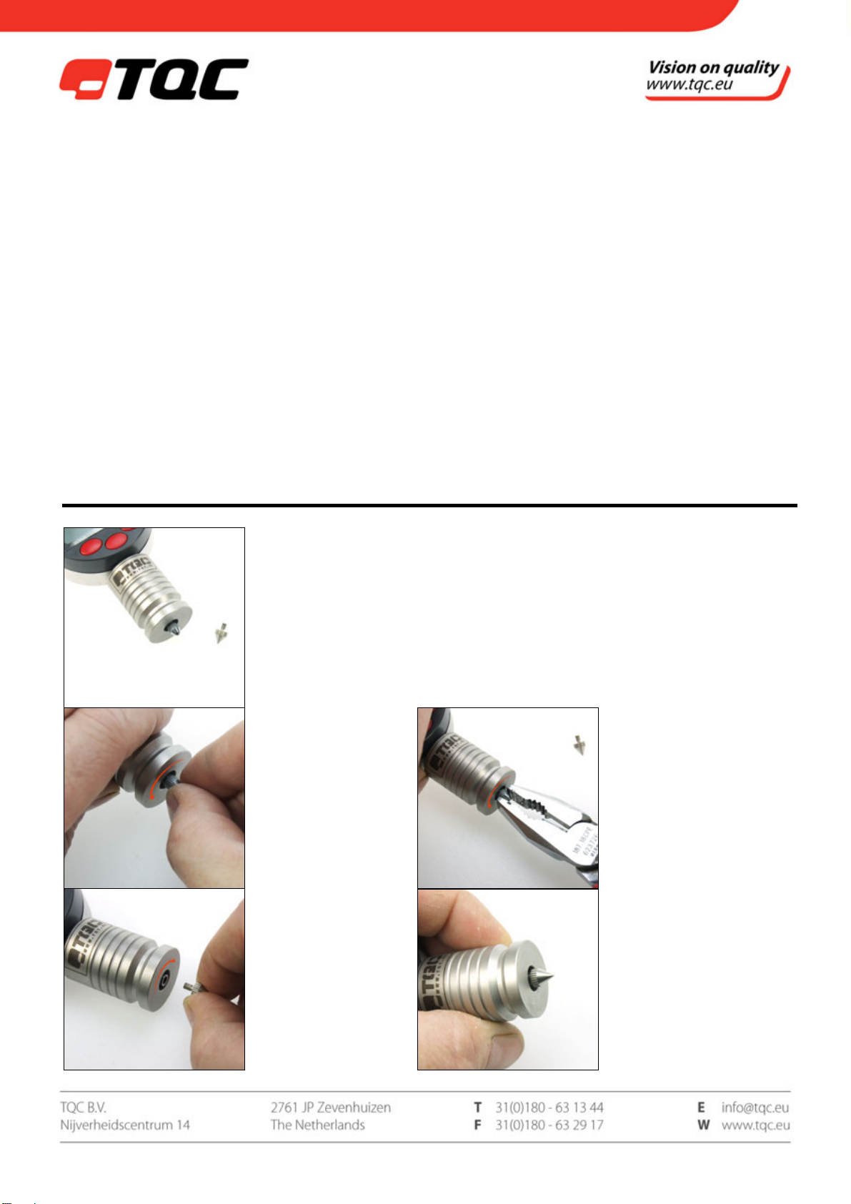
6CHANGING TIPS
Step 1
Two tips are supplied.
The sharp needle tip is
suitable for measuring
roughness, the round
one for thickness.
Step 2
Take the tip between
two fingers and turn
anti-clockwise until it is
loose. If the tip stays
stuck, go to step 2a.
Step 2a
Only when loosening the tip
anti-clockwise by hand fails,
a pair of tongs may be used
GENTLY. Make sure the tip
remains undamaged.
Step 3
Turn the new tip
clockwise until it’s
stuck.
Step 4
The tips have been changed.
Don’t forget to store the tip
that’s not in use.

3
|
7BATTERY REPLACEMENT
If the display blinks it’s necessary to replace the battery. The battery compartment lid is the grey cap on top of
the gauge. Remove it by lifting it with a small screw driver.
Replace the LR44 battery with its positive side facing upwards.
8CALIBRATIONS
We recommend annual calibration. You can send the instrument to the TQC Service department, together with
a completed RMA form. This form is available on www.tqc.eu under the Service-menu ; Repairs / Calibrations
9MAINTENANCE
•Though robust in design, this instrument is precision-machined. Never drop it or knock it over
•Always clean the instrument after use.
•Clean the instrument using a soft dry cloth. Never clean the instrument by any mechanical means such as a
wire brush or abrasive paper. This may cause, just like the use of aggressive cleaning agents, permanent
damage.
•Do not use compressed air to clean the instrument.
•Always keep the instrument in its case when not in use.
10 DISCLAIMER
The right of technical modifications is reserved.
The information given in this manual is not intended to be exhaustive and any person using the product for any
purpose other than that specifically recommended in this manual without first obtaining written confirmation
from us as to the suitability of the product for the intended purpose does so at his own risk. Whilst we
endeavour to ensure that all advice we give about the product (whether in this manual or otherwise) is correct
we have no control over either the quality or condition of the product or the many factors affecting the use and
application of the product. Therefore, unless we specifically agree in writing to do so, we do not accept any
liability whatsoever or howsoever arising for the performance of the product or for any loss or damage (other
than death or personal injury resulting from our negligence) arising out of the use of the product. The
information contained in this manual is liable to modification from time to time in the light of experience and
our policy of continuous product development.
1 |
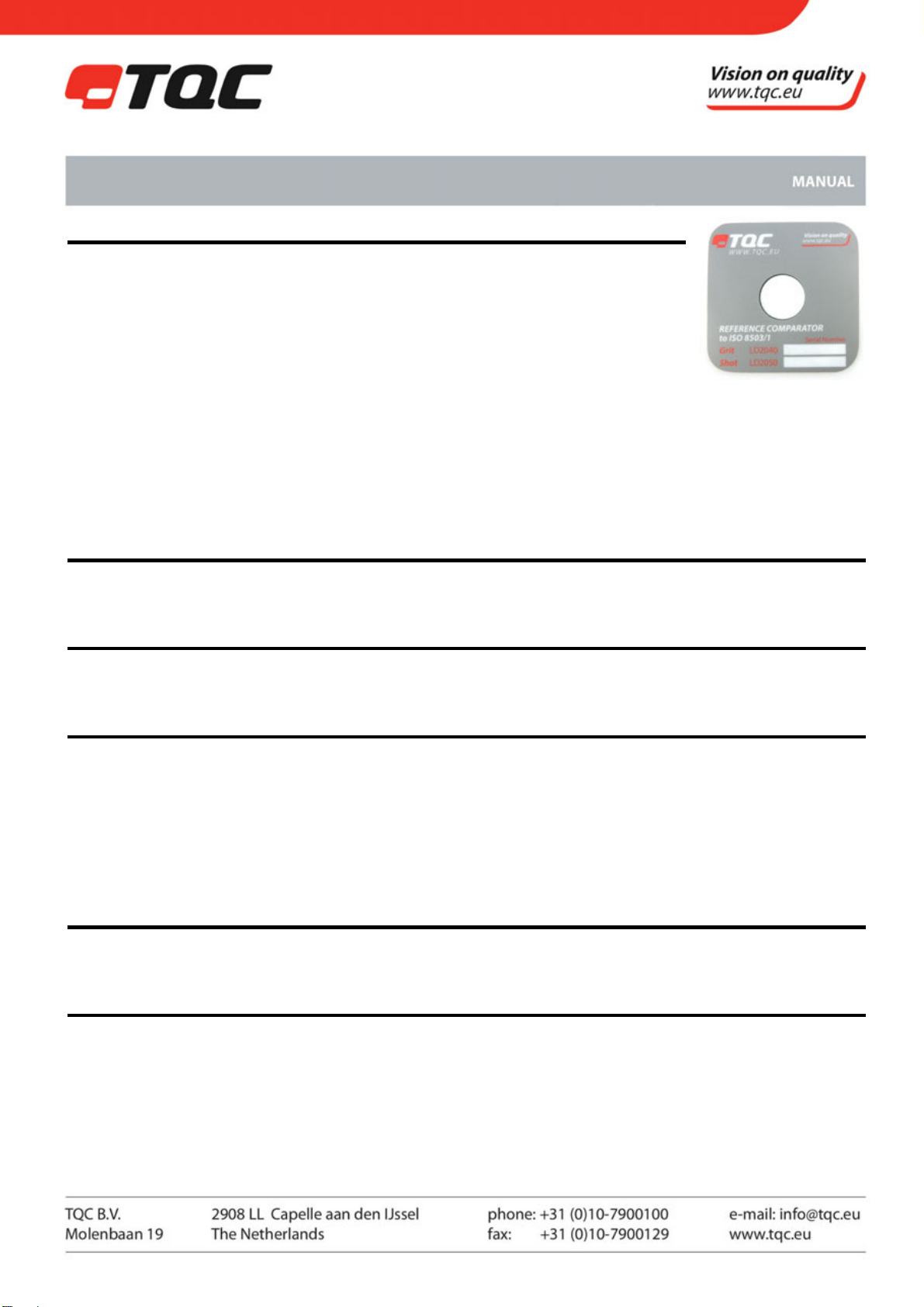
STEEL SURFACE ROUGHNESS COMPARATOR
LD2040, LD2050
1PRODUCT DESCRIPTION
Comparison standard according to ISO 8503 part 1 made of quality steel. Indicates the
surface condition of blasted steel according to ISO 8503 in grades of fine, medium,
and coarse.
1.1 Specifications
LD2040 - Surface Roughness Comparator for Grit Blasting
LD2050 - Surface Roughness Comparator for Shot Blasting
Material : High purity nickel
Width : 85mm
Height : 85mm
The comparator has been reproduced from a specially prepared and numbered master block
2STANDARDS
ASTM D 4417 Method A, ISO 8503-1
3WHAT’S IN THE BOX?
The Surface Roughness Comparator comes in a sturdy leather wallet.
4PERFORM A MEASUREMENT
By placing the appropriate comparator (G for Grit, S for Shot) against a blast cleaned surface, the finish achieved
can be compared against the four sections of the comparator. It is then a simple matter to identify (by sight and
touch) the standard surface:
Fine grade equal to or above segment 1 but below segment 2
Medium grade equal to or above segment 2 but below segment 3
Coarse grade equal to or above segment 3 but below segment 4
5MAINTENANCE
Always keep the instrument in its case when not in use.
6DISCLAIMER
The right of technical modifications is reserved.
The information given in this manual is not intended to be exhaustive and any person using the product for any
purpose other than that specifically recommended in this manual without first obtaining written confirmation
from us as to the suitability of the product for the intended purpose does so at his own risk. Whilst we
endeavour to ensure that all advice we give about the product (whether in this manual or otherwise) is correct

2 |
we have no control over either the quality or condition of the product or the many factors affecting the use and
application of the product. Therefore, unless we specifically agree in writing to do so, we do not accept any
liability whatsoever or howsoever arising for the performance of the product or for any loss or damage (other
than death or personal injury resulting from our negligence) arising out of the use of the product. The
information contained in this manual is liable to modification from time to time in the light of experience and
our policy of continuous product development.

1 |
UV POCKET FLASHLIGHT
LD7290
1SAFETY PRECAUTIONS
WARNING: The light from this flashlight is very powerful and should not be
shone directly into anyone's eyes, as this may cause short term blindness. If the
beam does shine in your eyes, close them and look away immediately.
2PRODUCT DESCRIPTION
Small, light weight, UV pocket flashlight powered by an ultra-high output 390-
410nm UV LED. This TQC UV pocket flashlight is used to detect contaminations that react under UV-
illumination and cannot be seen with naked eye such as some organic fats, alkaline contaminants etc. Ideal to
inspect the cleanliness of steel prior to painting.
2.1 Specifications
Light Source : LED
Chip : 1x Edixeon UV LED
Batteries : 3xAAA alkaline batteries
Net. weight : 76 grams excl. batteries
Wavelength : 395-410 NM
Beam distance : 50 meters
Burning time : 170 hours
IP No. : IP67
Contacts : Hard gold-plated contacts
Size : 32 x 126mm
3WHAT’S IN THE BOX?
UV pocket flashlight
3 x AAA alkaline battery
Wrist strap
Pouch
4PERFORM A MEASUREMENT
4.1 installing the batteries
Hold the aluminium casing firmly in one hand and
turn the end cap in a counter clockwise direction
until fully unscrewed (see figure) Pull the end cap
away from the casing and this will reveal the battery
cartridge. Place each battery in turn within the
cartridge ensuring that the polarity marks (+ and -)
on the battery match that of the cartridge. With all
LD7290

2 |
batteries installed replace the cartridge in to the casing and turn the end cap in a clockwise direction until fully
tightened. The flashlight is now ready to use.
IMPORTANT: please make sure the batteries are installed correctly otherwise battery damage may occur,
possibly resulting in a explosion. Never try to recharge batteries or use new and used batteries together. Always
change all the batteries at the same time and only use high quality ones. Be careful not to touch the gold
contacts at the end of the battery cartridge or rest them against anything conductive as this could cause short
circuit. If you do not intend to use the flashlight for a long period of time, remove the batteries to prevent them
leaking and damaging the flashlight.
4.2 operating the flashlight
To switch on the flashlight simply press the end cap switch until it engages, then release. To switch the
flashlight off, press the end cap switch once again until it disengages, then release.
5DISCLAIMER
The right of technical modifications is reserved.
The information given in this manual is not intended to be exhaustive and any person using the product for any
purpose other than that specifically recommended in this manual without first obtaining written confirmation
from us as to the suitability of the product for the intended purpose does so at his own risk. Whilst we
endeavour to ensure that all advice we give about the product (whether in this manual or otherwise) is correct
we have no control over either the quality or condition of the product or the many factors affecting the use and
application of the product. Therefore, unless we specifically agree in writing to do so, we do not accept any
liability whatsoever or howsoever arising for the performance of the product or for any loss or damage (other
than death or personal injury resulting from our negligence) arising out of the use of the product. The
information contained in this manual is liable to modification from time to time in the light of experience and
our policy of continuous product development.
Table of contents
Other TQC Test Equipment manuals


 User handbook")


