TQC AB6000 User manual

TQC Scrub Abrasion and
Washability Tester
(AB6000, AB6010)
Operating Instructions (V1.1 0118)
IMPORTANT! Before taking this instrument
in use we strongly advise you to read this
manual carefully.


3 |
TQC will grant a warranty for a period of 12 months for the TQC Scrub
Abrasion and Washability Tester and 12 months for all related equipment
from the date of delivery in respect of any evidence of faulty workmanship
and materials.
Should a delivered consignment prove to be contrary to contract upon
inspection, the customer shall grant TQC the opportunity hereunder of
removing the fault, or else the customer may demand replacement. Because
of size and weight of the instrument TQC will strive to give remote support.
Should the supply or delivery of any improvement or replacement not prove
possible, the customer may choose between having the purchase price
reduced or in demanding the contract of sale to be rescinded (conversion).
Damage resulting from natural wear and tear, mechanical or chemical
damage, an act of God or non compliance with the operating instructions
shall be excluded from the warranty as well as mechanical interference by
the customer or by third parties with TQC Scrub Abrasion and Washability
Tester and related equipment without TQC’s written permission. No liability
will be accepted for defects, damage or injury caused due to use not carried
out in accordance with the manufacturer’s user instructions.
To claim warranty, the rejected product has to be sent to TQC together with
the original invoice, any exchange before the product has been returned
to TQC is not possible. TQC reserve the right to repair, exchange or supply
an equivalent substitute. TQC is not liable for handling or transport costs.
Warranty on the purchase price is limited, all liability for consequential
damages or changes in technology is expelled.
This product complies to
- Machinery Directive 2006/42 / EC
- Low Voltage Directive 2006/95 / EC
- EMC Directive 2004/108 / EC
This product is RoHS 2 compliant (2011/65/EU)
WARRANTY


5 |
1 General
1.1 Importance of operating manual
1.2 User-responsibility
1.3 Responsibility of personnel
1.4 Dangers
1.5 Designated purpose
1.6 Copyright
1.7 Manufacturer’s/Supplier’s address
2 Safety Instructions
2.1 Meaning of Symbols
2.2 Availability of Safety Information
2.3 Dangers from Electrical Energy
2.4 Modifications to the Equipment
3 Transport and Storage
3.1 Packing
3.2 User: Check on Receipt
3.3 Reporting Transport Damage and
Documentation
3.4 Storage and Protective
Measures when not in use
4 Instrument Data
4.1 Name / Article
4.2 Scope of Supply
4.3 Technical Data
4.4 Dimensions and Weight
4.5 Basic Unit
5 Instrument Controls and Functions
5.1 Instrument Layout
5.2 Connecting a Mouse and Keyboard
6 Instrument Preperations
6.1 Installation
6.2 Tool Holders and Tools
6.3 Fluid Tubes
7 Navigation
7.1 Menu
7.2 Number Input
7.3 Text Input
8 Operation
8.1 Starting the Instrument
8.2 Run
8.2.1 Run
8.2.2 Manual Movement
8.3 Run Setup
8.3.1 Manual
8.3.2 Alarms
8.3.3 Pumps
8.3.4 Custom Presets
8.3.5 New Custom Preset
8.3.6 Standard Presets
8.3.7 Select Length
8.3.8 Test Positioning
8.3.9 Flush System (AB6000 only)
9 Instrument Setup
9.1 Instrument Setup Menu
9.2 Units
9.3 Alarms
9.4 Display Brightness
9.5 System Information
9.6 Reset
10 Mechanical
10.1 Test Beds
10.2 Sample Clamp Frames
10.3 Tool Holders
10.4 Tools
10.4.1 Small Sponge (AB5012)
10.4.2 Wild Boar Brush (AB5010)
10.4.3 Nylon Brush (AB5011)
10.4.4 Abrasive Pad Tool (AB5013)
10.4.5 Universal Material Clamp (AB5020)
10.4.6 MEK / Crockmeter Tool (AB5060)
10.4.7 Large Sponge Tool (AB5050)
10.4.8 TQC Cloth Holder (AB5055)
10.4.9 Metal Shim (AB5025)
10.4.10 Glass Bed (AB5180)
10.4.11 Heavy Weight Support Tool (AB5032)
10.4.12 Tubing (AB5115 and AB5113)
11 Care and Maintenance
11.1 Disposal of Materials
11.2 Customer Service
12 Disclaimer
Annex A Standards Conguration Table
Annex B Chemical Resistance
Annex C Operator Qualication List
Annex D Maintenance List
6 21/22
23/27
28
29
30/31
32/43
45
47
7
8
9
10/11
12
13
14/20
INDEX

| 6
1.1 Importance of operating manual
This manual is written in order to become familiar with all the functions and
possible applications of the instrument. It contains important instructions
about how to use the instrument safely and economically; according to
the purpose designated. Following these instructions is not only essential
to avoid risks. It also reduces repair costs and down-time and increases the
products reliability and service-life.
Anyone who works with the instrument shall follow the instructions in this
manual, particularly the safety related instructions. Additionally local rules
and regulations relating to environmental safety and accident prevention
should be observed. It is mandatory that users have read and understand
this manual prior to first operation of the TQC Scrub Abrasion and
Washability Tester.
1.2 User-responsibility
The user should
a) Only allow persons to work with the instrument who are
familiar with the general instructions on how to work safely and
to prevent accidents. The use of the instrument should have been
instructed duly.
b) Regularly check the safety-awareness of personnel at work.
1.3 Responsibility of personnel
Before commencing work anyone appointed to work with the instrument
should pay attention to the general regulations relating to working safety
and accident prevention. The safety chapter and the warnings in this manual
should have been read and understood; acknowledged as evidenced by
their signature as can be placed in the Operator Qualification list Annex C.
1.4 Dangers
This instrument has been designed and constructed in accordance with
state-of-the-art technology and the acknowledged safety regulations.
Nevertheless, working with the instrument could cause danger to the
life and health of the operator or to others, or damage to the instrument
or other property. Therefore the instrument should only be used for its
designated purpose, and in a perfect technical condition. Any defect that
could have a negative effect on safety should be repaired and recorded.
1.5 Designated purpose
TQC Scrub Abrasion and Washability Tester is exclusively designed to
perform washability tests of painted and coated test panels as described
within the specifications. TQC will not be held liable for damage resulting
from improper use.
Designated purpose also includes properly observing all instructions in the
operation manual, and adherence to inspection and maintenance
schedules. TQC is entitled to request these form when warranty claims are
made and during inspections to ensure safe operation and evaluate correct
usage.
1.6 Copyright
The copyright of this operating manual remains with TQC. This operating
manual is intended solely for the user and his personnel. Its instructions
and guidelines may not be duplicated, circulated or otherwise passed on to
others, neither fully, nor partly. Infringement of these restrictions may lead
to legal action may be taken if this restrictions are infringed upon.
1.7 Manufacturer’s/Supplier’s address
TQC – Molenbaan 19
2908 LL Capelle aan den IJssel
The Netherlands
T +31(0)10 7900 100
F +31 (0)10 7900 129
1 GENERAL

7 |
2.1 Meaning of Symbols
The following symbols for dangers are used in this instruction manual.
2.2 Availability of Safety Information
The instruction manual should be kept in proximity to where the instrument
operates and should be visible and accessible at any time of operation.
In addition to the information contained in the instruction manual, general
and local regulations for accident prevention and environmental protection
shall be kept available and observed. Always ensure all guidelines in respect
of safety and dangers on the instrument are in readable condition.
In case of danger the instrument has to be switched off by means of the on /
off switch at the left back side of the instrument or by unplugging the mains
power, then the danger should be eliminated.
2.3 Dangers from Electrical Energy
• Work on the electrical supply may only be done by a qualified electrician.
• The electrical equipment of the instrument must be checked regularly.
Loose connections and cables damaged by heat must be corrected
immediately.
• Always make sure the instrument’s power is turned off while adjusting any
electrical component.
Make sure that no paint or other liquids are spilled on the
electronics
2.4 Modications to the Equipment
• Any modifications or additions or alterations to the instrument may solely
be made with permission from the manufacturer otherwise the warranty
will be void.
• Instruments which are not in fault-free condition must immediately be
switched off
• Only use replacement parts from the original supplier. Parts used from
other sources aren’t guaranteed to take the loading and meet the safety
requirements.
Possible immediate
danger to the life or
health of personnel.
If this guideline is not noted
it can lead to severe danger
to health, up to fatal injury.
A dangerous situation
could be caused.
Non observance of this
guideline can lead to injury
or to damage to equipment.
Special tips and
particular information.
Guidelines to make optimal
use of the instrument.
2 SAFETY INSTRUCTIONS

| 8
3.1 Packing
• Please take note of pictorial symbols on the packing.
• Check for transport damages. If the packaging is damaged only accept it
with a written approval of the transporter that the package was damaged.
3.2 User: Check on Receipt
• Check packing for damage
• After unpacking check complete supply.
3.3 Reporting Transport Damage and Documentation
• Any damage should be documented as accurately as possible (possibly
photographed) and reported to the relevant insurers or, in the case of sales
“delivered to customers works”, to the supplier.
3.4 Storage and Protective Measures when not in use
• The instrument must be stored in a dry place at a temperature
between 10 - 40˚C / 50 - 104˚F.
• If packing is damaged upon receipt immediately inform the forwarder and
make a note on the packing list and have it signed by the forwarder. Ideally
make some pictures of the damage as well.
• Store instrument in the original packing if possible.
3 TRANSPORT AND STORAGE

9 |
4 INSTRUMENT DATA
TQC Scrub Abrasion and
Washability Tester
24 V Adapter +
Power Cable
Manual Tubing Fluid Containers
Standard supplied Only supplied with AB6000
4.3 Technical Data
Traverse speed: 1 - 60 cycles per minute
Traverse speed accuracy: + / - 1% of set speed
Stroke length: 20 - 300 mm / 0.39 - 11.81 in
Stroke length accuracy: + / - 0.01 mm
Pump flow rate: 0.0 - 3.0 ml per minute / 0.0 - 0.79 GPH
Max. panel width: 70 mm
Max. panel length: 350 mm
Max. panel height: 35 mm
4.4 Dimensions and Weight
Depth: 490 mm / 19.3 in
Depth with pumps: 530 mm / 20.87 in
Width: 640 mm / 25.2 in
Height: 235 mm / 9.24 in
Weight: 30 - 35 kg / 66.14 - 77.16 lbs (depending on model)
4.5 Basic Unit
Power Supply: 24 VDC / 100 - 240 V / 50 - 60 Hz
Power consumption: max. 90 Watt
Display: 480 x 272 pixel TFT display
Control: 5-key navigation switch
(Mouse Keyboard optional)
Menu languages: English, Spanish, Chinese, Polish, German, French,
Italian, Japanese, Russian, Turkish
4.1 Name / Article
AB6000 TQC Scrub Abrasion and Washability Tester
AB6010 TQC Scrub Abrasion and Washability Tester Basic
4.2 Scope of Supply
TQC Scrub Abrasion and
| 10
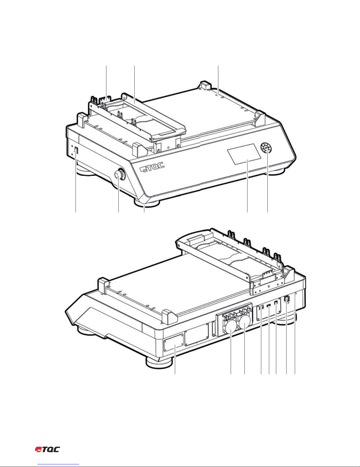
5 INSTRUMENT LAYOUT AND FUNCTIONS
Tube Holder
Tool Carrier
Fixture Screws
Power Switch
Emergency Button
Adjustable Feet
Full Color Display
5-key Navigation Switch
5
6
7
8
9
10
11
12
13
14
15
16
1
2
3
4
Machine ID-Tag
Pump AB
Pump CD
Ethernet
USB-A
USB-B
TQC Bus
Power Entry
45
910111213141516
678
12 3
5.1 Instrument Layout
11 |
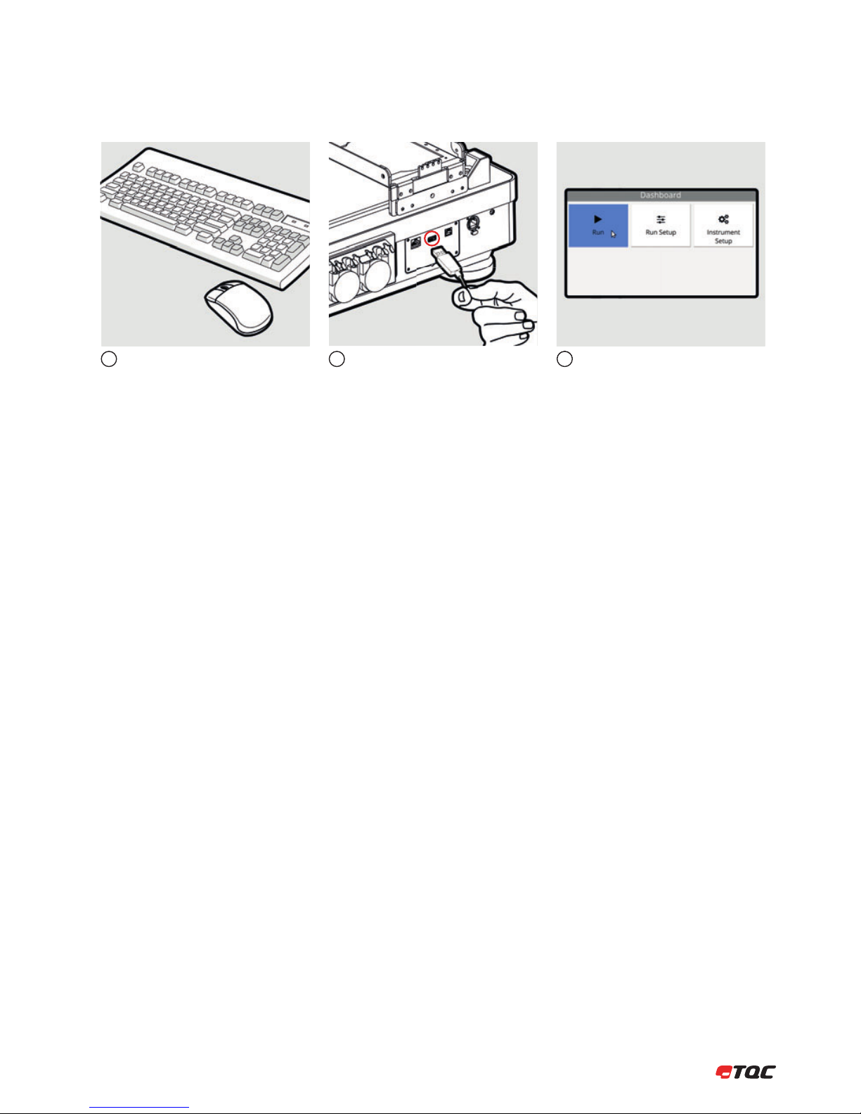
5.2 Connecting a Mouse and Keyboard
The instrument can also be controlled by a
mouse and/or keyboard.
Connect the mouse and/or keyboard to the
USB-A port at the back of the instrument.
Clicking the left mouse button behaves the
same as the OK button. (Not all input fields
can be controlled by a mouse.)
123
Clicking the left mouse button behaves the
3

| 12
6 INSTRUMENT PREPARATIONS
The instrument has to be installed on a
sturdy table or work area.
Lift the Tool Carrier.
Connect the power cable to the machine
and a wall socket.
Place the Test Beds and the Sample Clamp
Frames. Then close the Tool Carrier.
Place the Tool Holders first, then place the
Tools.
1
1
2
23
6.1 Installation
6.2 Tool Holders and Tools
6.3 Fluid Tubes
Mount the tubes in the bracket on the Tool
Carrier and place the correct tube at each
channel.
Connect the IN tubes from the pumps to
the fluid containers.
23
Connect the tubes to the fluid pumps. The
channels are marked on bracket.
1
13 |
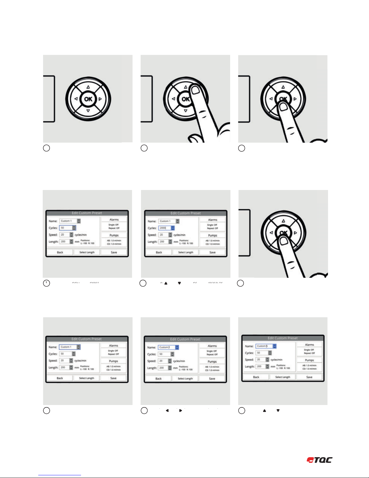
7 NAVIGATION
Use the 5-key button to navigate through
the interface. Red lights in the 5-key button
indicate possible actions for the selected
button.
You can change the selected button by
pressing the arrows on the 5-key button.
12 To confirm the selected button, press OK on
the 5-key button.
3
Select the input and press OK to edit the
value.
Use the and buttons to increase or
decrease the value. Hold the button to
increase or decrease in bigger steps.
Use the and buttons to select the
character.
Use the and buttons to change the
character.
Press OK to stop editing.
12
23
3
Select the input and press OK to edit the
value.
1
7.2 Number Input
7.1 Menu
7.3 Text Input
Sel
ect
th
ei
npu
ta
nd
pre
ss
OK
to
ed
it
the
K
1
Use th
e
and bu
tto
ns
to
inc
rea
se
or
2
h
db l h

| 14
8.1 Starting the Instrument
8 OPERATION
Press OK to initialize the instrument.This screen will be displayed after turning
on the instrument.
The instrument will check the system
for any errors and the Tool Carrier will be
calibrated.
12
Run
Click to start a new run.
Run Setup
Run related settings.
Instrument Setup
All instrument related settings.
3
Check fluids presence at tip of tubes.
(AB6000 only)
Follow the instructions on the display.
12 Place and secure tools.3
8.2 Run
8.2.1 Run
Follow the instructions on the display
2

15 |
Follow the instructions on the display.
A name or description can be given to the
marking. Click Conrm to save the marking.
The Tool Carrier will now move. Stay clear
from moving parts!
4
7
5
89
Click A, B,C,or D to mark a single channel
at current cycles/time. Click All to mark all
channels at current cycles/time. Click Pause
to temporarily stop the test.
Click Markings to view all markings of the
current run. Click Resume to continue the
run. Click Stop to stop the run.
Use the and buttons to scroll through
the list of markings. Click Clear to erase all
current markings.
6
Tools may be removed when the Tool
Carrier has stopped moving.
10
Follow the instructions on the displ
ay
4
Click
A
B
C
or D
to mark a single channel
6
An
ame
or
de
scr
ipt
ion
ca
nb
eg
ie
nt
ot
he
7
8
Click
Markings
to view all markings of the
| 16
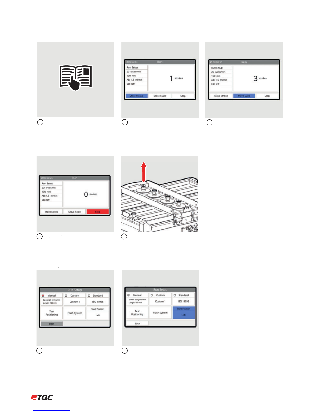
8.2.2 Manual Movement
See steps 1 – 4 from chapter 8.2.1.
8.2.1.
Click Move Stroke to move the Tool Carrier
a single stroke. (from Left to Right or Right
to Left, depending on set Start Position)
12 Click Move Cycle to move the Tool Carrier a
single cycle.
3
Click Stop to stop the run.
4Tools may be removed when the Tool
Carrier has stopped moving.
5
Run settings are set in Manual, Custom or
Standard. The red checkmark indicates the
active setup.
Click to set the movement start position to
Left or Right.
12
8.3 Run Setup
8.3
Run
Setup
Click
Move Stroke
to move the Tool Carrier
2
Click
Move Cycle
to move the Tool Carrier a
3
Click
St
op
k
to sto
p t
he run
.
4
Cli k t t th t t t iti t
2

17 |
Set the speed and length. Click Alarms to configure the alarms
settings. Click Pumps to configure the
pumps settings. (AB6000 only)
If uncertain about the left and right
position, use Select Length to determine
the positions. See 8.3.7.
123
8.3.1 Manual
Click Select to use the manual setup. Enable Manual Movement for manual
control of the Tool Carrier in a run.
45
8.3.1
Manual
Manual Movement
Instead of automatic movement, the user
can move the Tool Carrier a single stroke or
cycle by the click of a button. See 8.2.2 for
more information.
Single alarm will make a sound once at set
number of cycles. Enable Stop at alarm
to stop the Tool Carrier when an alarm is
triggered.
Repeat alarm will make a sound at set
interval.
Click Back to save the alarm settings.
123
8.3.2 Alarms
8.3
.2
Ala
rms
Cli k
Bk
t th l tti
3
| 18
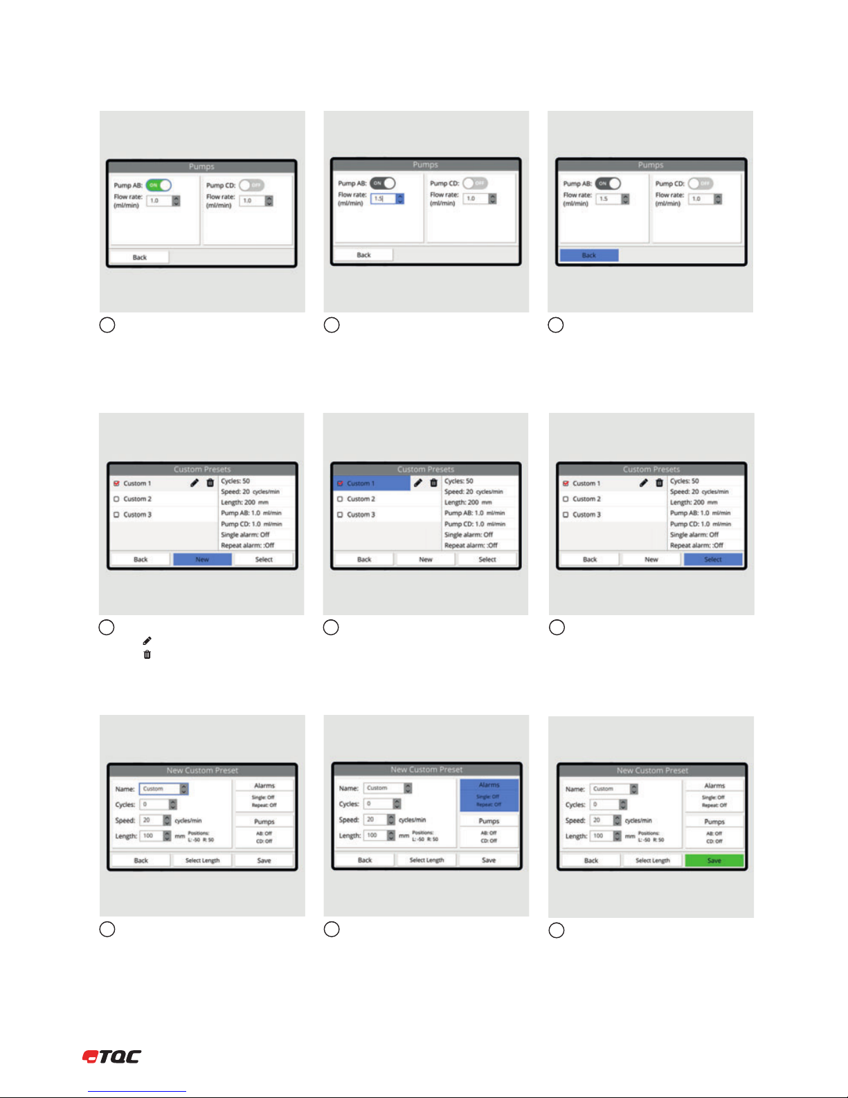
Enable or disable a pump. Set the flow rate speed. Click Back to save the pumps settings.
123
8.3.3 Pumps
Click New to create a new custom preset.
Click to edit the selected preset.
Click to delete the selected preset.
The selected preset’s settings are listed on
the right.
12 Click Select to use the selected custom
preset.
3
8.3.4 Custom Presets
Similar to Manual, set the A, B, C, and D.
A name can be given to the custom preset.
Click Alarms to configure the alarms
settings. Click Pumps to configure the
pumps settings. (AB6000 only)
12 Click Save to save the new custom preset.
The new preset will be listed in the Custom
Presets menu.
3
8.3.5 New Custom Preset
Click
Back
to save the pumps settings
3
19 |
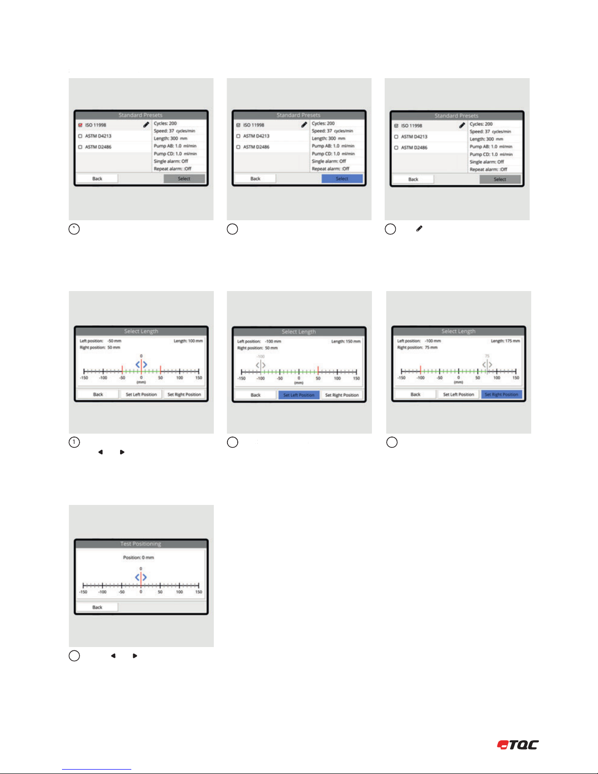
Predefined presets according several
standards.
Click Select to use the selected standard
preset.
Click to edit the number of cycles.
123
8.3.6 Standard Presets
Move the tool carrier by using
the and buttons. Make sure the Tool
Carrier can move freely.
Click Set Left Position to set the current
position as left position.
12 Click Set Right Position to set the current
position as right position.
3
8.3.7 Select Length
Move the tool carrier by using
1
Click
Set Left Position
to set the current
2
Click
Set Right Posit
ion
to set the current
3
Use the and buttons to move the
Tool Carrier. Left and Right position for
irregular test objects can be determined.
1
8.3.8 Test Positioning
Predefined presets according se eral
1
8.3.6
St
a
n
da
r
d
Preset
s
Click
Select
to use the selected standard
2
Click to edit the number of cycles
3
| 20
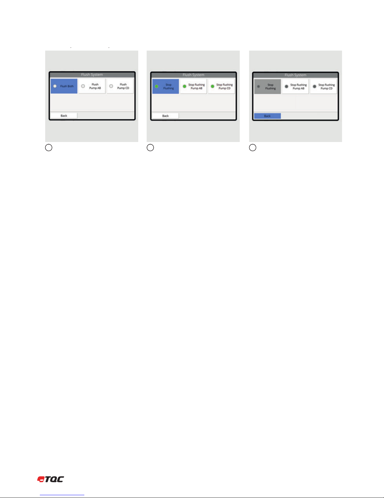
Click Flush Both to start both fluid pumps. Click Flush Pump AB or Flush Pump CD to
start one of the pumps.
12 Click Back to return to the Run Setup menu.
Active pumps will be stopped.
3
8.3.9 Flush System (AB6000 only)
yy
This manual suits for next models
1
Table of contents
Other TQC Test Equipment manuals


