TQC SP4300 User manual

TQC AUTOMATIC CUPPING TEST
SP4300
IMPORTANT!
Before taking this instrument in use we strongly
advise you to read this manual carefully.
Operating Instructions for the
AUTOMATIC CUPPING TEST
MICROPROCESSOR CONTROLLED
v1.02 1014

2
|
1 General............................................................................................................................................................... 4
1.1 Importance of operating manual......................................................................................................................................4
1.2 User-responsibility..................................................................................................................................................................4
1.3 Responsibility of personnel.................................................................................................................................................4
1.4 Dangers ......................................................................................................................................................................................4
1.5 Designated purpose ..............................................................................................................................................................4
1.6 Copyright ...................................................................................................................................................................................4
1.7 Manufacturer's/Supplier's address ...................................................................................................................................4
2 Safety Instructions ............................................................................................................................................ 5
2.1 Meaning of Symbols ..............................................................................................................................................................5
2.2 Availability of Safety Information......................................................................................................................................5
2.3 Training of Personnel.............................................................................................................................................................5
2.4 Dangers from Electrical Energy..........................................................................................................................................5
2.5 Points of Special Danger ......................................................................................................................................................5
2.6 Care, Maintenance, Repairs .................................................................................................................................................6
3 Transport and Storage...................................................................................................................................... 6
3.1 Packing .......................................................................................................................................................................................6
3.2 User: Check on Receipt .........................................................................................................................................................6
3.3 Reporting Transport Damage and Documentation ...................................................................................................6
3.4 Storage and Protective Measures when not in use ....................................................................................................6
4 Instrument Data ................................................................................................................................................ 7
4.1 Name / Article...........................................................................................................................................................................7
4.2 Scope of Supply.......................................................................................................................................................................7
4.3 Technical Data..........................................................................................................................................................................7
4.4 Dimensions and Weight .......................................................................................................................................................7
4.5 Basic Unit....................................................................................................................................................................................7
4.6 Accuracy.....................................................................................................................................................................................7
4.7 Noise Level ................................................................................................................................................................................7
5 Installation and Assembly ................................................................................................................................ 8
5.1 Installation and Operation...................................................................................................................................................8
This product complies to
- Machinery Directive 2006/42 / EC
- Low Voltage Directive 2006/95 / EC
- EMC Directive 2004/108 / EC

3
|
5.2 Preparation of Energy Connections .................................................................................................................................8
5.3 Mains Connection...................................................................................................................................................................8
6 Instrument controls and functions .................................................................................................................. 9
7 Instrument preparations ..............................................................................Fout! Bladwijzer niet gedefinieerd.
7.1 Test Panels..............................................................................................................................................................................10
7.2 Calibration plate................................................................................................................................................................... 10
7.3 Optical tool fixture rod....................................................................................................................................................... 10
7.4 Panel clamp............................................................................................................................................................................10
7.5 Moving the Sample holder...............................................................................................................................................10
8 Menu display information and operation .....................................................................................................10
8.1 TQC Start screens after switched on. ............................................................................................................................ 10
8.2 MAIN MENU............................................................................................................................................................................ 11
8.3 RUN SETUP.............................................................................................................................................................................. 11
8.3.1 RUN SETUP – Preset test......................................................................................................................................... 11
8.4 LIGHT SETUP ..........................................................................................................................................................................11
8.5 INSTRUMENT SETUP............................................................................................................................................................ 11
8.6 INSTRUMENT SETUP – INDENTER SPEED.....................................................................................................................12
8.7 INSTRUMENT SETUP – DEPTH SIGNAL.......................................................................................................................... 12
8.8 INSTRUMENT SETUP – SETUP TIME/DATE................................................................................................................... 12
8.9 INTRUMENT SETUP – UNITS .............................................................................................................................................12
8.10 INSTRUMENT SETUP – ACOUSTICS.............................................................................................................................. 12
8.11 INSTRUMENT SETUP – LANGUAGE.............................................................................................................................. 12
8.12 INSTRUMENT SETUP – CALIBRATION .........................................................................................................................13
8.13 CALIBRATE............................................................................................................................................................................ 13
8.14 CALIBRATION – HISTORY ................................................................................................................................................ 13
8.15 INSTRUMENT SETUP – OPTICS ADJ. ............................................................................................................................ 14
8.16 RUN.........................................................................................................................................................................................14
8.17 PRESET RUN .........................................................................................................................................................................14
8.18 MANUAL RUN......................................................................................................................................................................15
8.19 Warning signals.................................................................................................................................................................. 15
9 Operation.........................................................................................................................................................16
9.1 Preparatory Work................................................................................................................................................................. 16
9.2 Performing a Cupping........................................................................................................................................................16
9.3 Start the instrument............................................................................................................................................................16
10 Care and Maintenance..................................................................................................................................16
10.1 Inspection and Maintenance.........................................................................................................................................16
10.2 Disposal of Materials ........................................................................................................................................................ 16
10.3 Customer Service...............................................................................................................................................................16
11 Disclaimer......................................................................................................................................................16

4
|
1GENERAL
1.1 Importance of operating manual
This manual is written in order to become familiar with all the functions and possible applications of the
instrument. It contains important instructions about how to use the instrument safely and economically;
according to the purpose designated. Following these instructions is not only essential to avoid risks. It also
reduces repair costs and down-time and increases the products reliability and service-life.
Anyone who works with the instrument should follow the instructions in this manual, particularly the safety
related instructions. Additionally local rules and regulations relating to environmental safety and accident
prevention should be observed.
1.2 User-responsibility
The user should
a) only allow persons to work with the instrument who are familiar with the general instructions on how to
work safely and to prevent accidents. The use of the instrument should have been instructed duly The safety
chapter and the warnings in this manual should have been read and understood; acknowledged as
evidenced by their signature.
b) regularly check the safety-awareness of personnel at work.
1.3 Responsibility of personnel
Before commencing work anyone appointed to work with the instrument should pay attention to the general
regulations relating to working safety and accident prevention. The safety chapter and the warnings in this
manual should have been read and understood; acknowledged as evidenced by their signature.
1.4 Dangers
This instrument has been designed and constructed in accordance with state-of-the-art technology and the
acknowledged safety regulations. Nevertheless, working with the instrument may cause danger to the life and
health of the operator or to others, or damage to the instrument or other property. Therefore the instrument
should only be used for its designated purpose, and in a perfect technical condition. Any defect that could have
a negative effect on safety should be repaired immediately.
1.5 Designated purpose
The TQC Automatic Cupping Tester is exclusively designed to perform cupping tests on painted and coated test
panels as described within the specifications.
Other applications constitute improper use. TQC will not be held liable for damage resulting from improper use.
Designated purpose also includes properly observing all instructions in the operation manual, and adherence to
inspection and maintenance schedules.
1.6 Copyright
The copyright of this operating manual remains with TQC.
This operating manual is intended solely for the user and his personnel. Its instructions and guidelines may not
be duplicated, circulated or otherwise passed on to others, neither fully, nor partly. Infringement of these
restrictions may lead to legal action may be taken if this restrictions are infringed upon.
1.7 Manufacturer's/Supplier's address
TQC - Molenbaan 19, 2908LL Capelle aan den IJssel - The Netherlands,
T +31(0)10 7900 100, F +31 (0)10 7900 111

5
|
2SAFETY INSTRUCTIONS
2.1 Meaning of Symbols
The following symbols for dangers are used in this instruction manual.
Symbol Explanation Warning
Danger
Possible immediate danger to the life or
health of personnel
If this guideline is not noted it can lead to
severe danger to health, up to fatal injury
Warning
A dangerous situation could be caused Non observance of this guideline can lead
to injury or to damage to equipment.
Special tips and particular information Guidelines to make optimal use of the
instrument.
2.2 Availability of Safety Information
The instruction manual should be kept at the place where the instrument operates.
In addition to the information contained in the instruction manual, general and local regulations for accident
prevention and environmental protection shall be kept available and observed.
Always ensure all guidelines in respect of safety and dangers on the instrument are in readable condition.
In case of danger the instrument has to be switched off by means of the emergency-button on the front of the
instrument. Then eliminate danger.
2.3 Training of Personnel
•Anyone who operates the instrument should be trained properly.
•It has to be clear who has which responsibility regarding commissioning, set-up of maintenance and
repairs, installation, and operation.
•Anyone who hasn’t finished training should be supervised by an experienced person while working with
the instrument.
2.4 Dangers from Electrical Energy
•Work on the electrical supply may only be done by a qualified electrician.
•The electrical equipment of the instrument must be checked regularly. Loose connections and cable
damaged by heat must be corrected immediately.
•IAlways make sure the instrument's power is turned off while adjusting any electrical component.
2.5 Points of Special Danger
There are some special points of danger::
Always have the adjustable test cylinder head locked in place prior to and during testing
Keep your hands away from the working area after the instrument has started!
Never put your fingers / hand in the sample holder

6
|
2.6 Care, Maintenance, Repairs
•Always make sure the instrument is connected to an earthed socket.
•Maintenance and inspection should be carried out at the correct intervals
•Operating personnel should be informed before starting with maintenance or repair work
•Always make sure the instruments power is turned off and the instrument is not connected to a socket
while adjusting any electrical component whenever maintenance, inspection or repair work is done.
•Do not open the instrument. In case of malfunction always consult the manufacturer.
2.7 Modifications to the Equipment
•Any modifications or additions or alterations to the instrument may solely be made with permission from
the manufacturer.
•All measures involving modifications require written confirmation of approval from TQC
•Instruments which are not in fault-free condition must immediately be switched off
•Only use replacement parts from the original supplier. Parts used from other sources aren’t guaranteed to
take the loading and meet the safety requirements.
2.8 Cleaning of the Instrument and Disposal of Materials
•When in use it is not always possible to avoid some spill of paint on the work surface.
•Try to keep the instrument as clean as possible to prevent distortions of functions.
•To clean the instrument properly use a suitable solvent to dispose remains of paint or ink.
•Wear gloves during cleaning; Don’t spill an overdose of solvent during cleaning.
•Cleaning materials must always be used and disposed of correctly.
3TRANSPORT AND STORAGE
3.1 Packing
Please take note of pictorial symbols on the packing.
3.2 User: Check on Receipt
Check packing for damage
After unpacking check complete supply.
3.3 Reporting Transport Damage and Documentation
Any damage should be documented as accurately as possible (possibly photographed) and reported to the
relevant insurers or, in the case of sales "delivered to customers works", to the supplier.
3.4 Storage and Protective Measures when not in use
The instrument must be stored in a dry place at a temperature between 10 - 40°C.
The storage period should not be longer than 3 months.
Store instrument in the original packing if possible.

7
|
4INSTRUMENT DATA
4.1 Name / Article
TQC Automatic Cupping Test – Microprocessor Controlled Automatic Cupping test.
4.2 Scope of Supply
•TQC Automatic Cupping Test
•Power cord
•Calibration plate
•Loupe & Microscope fixture rod
•Reference panel
•Manual
•Calibration Certificate
4.3 Technical Data
Indenter Speed: 0.01 – 0.70 mm/s
Stroke length: 0 - 12 mm
Max panel width: Max 100mm
Max. panel thickness steel: max. 0.8 mm
Max. panel thickness aluminium: max. 1.2 mm
.
4.4 Dimensions and Weight
Depth: 450 mm
Width: 350 mm
Height: 600 mm
Net weight: approx. 31 kg
4.5 Basic Unit
Power Supply: 115 – 230 V, 50 - 60 Hz
Power consumption: max. 80 Watt
Display: Blue Illuminated, graphic 100 x 35 mm, 193x64 pixels
Safety: Emergency Button, integrated Acoustic Alarm
Function: Jog Shuttle knob by Rotation / Pushing
4.6 Accuracy
Indenter Speed accuracy: +/- 1% of set speed
Stroke length accuracy: +/- 0.01 mm or 0.2% ever is greater
4.7 Noise Level
The continuous noise level from the instrument does not exceed 70 dB.
8
|
Warnin
g
5INSTALLATION AND ASSEMBLY
5.1 Installation and Operation
The instrument has to be installed in a suitable place, preferably on a sturdy table or work area, with normal
ambient temperature. Special fixings are not required.
Carefully unpack the apparatus and the accessories and check complete supply.
Place, if necessary, a spirit level on the work surface and adjust the height of the feet.
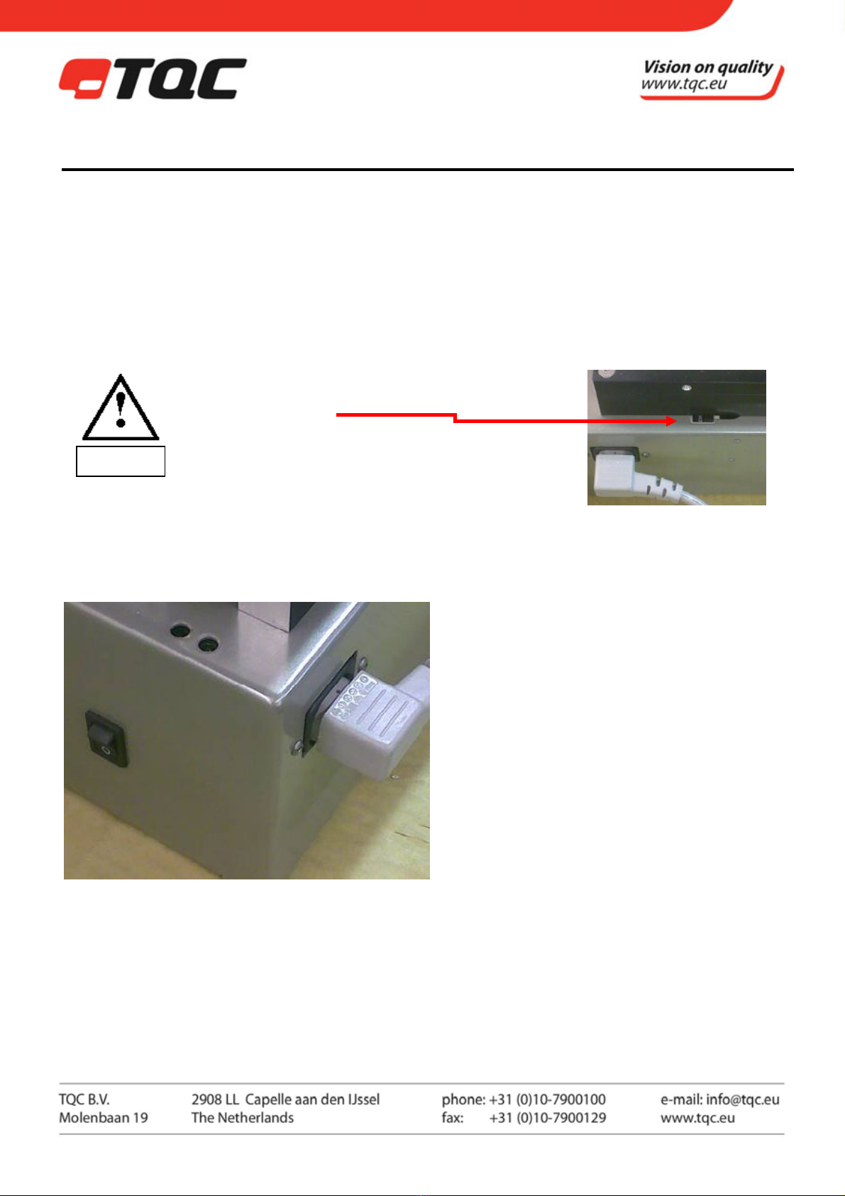
5.2 Preparation of Energy Connections
The instrument is equipped with a safety tested mains supply cable and may only be connected to plug sockets
with earth connection complying with the safety regulations.
Before connecting the instrument, check whether the supply
voltage specified in the indication window corresponds to
the local supply voltage.
If it does not, the instrument must not be connected under
any circumstances. This switch is located behind the esthetic
rear cover of the cupping test. Contact TQC or your local
contact to correctly set the switch
5.3 Mains Connection
The mains connection is located at the rear of the instrument. Plug in the female plug in the socket on the rear
of the housing. The ON/OFF Switch is located at the right hand site near the end of the instrument.
9
|
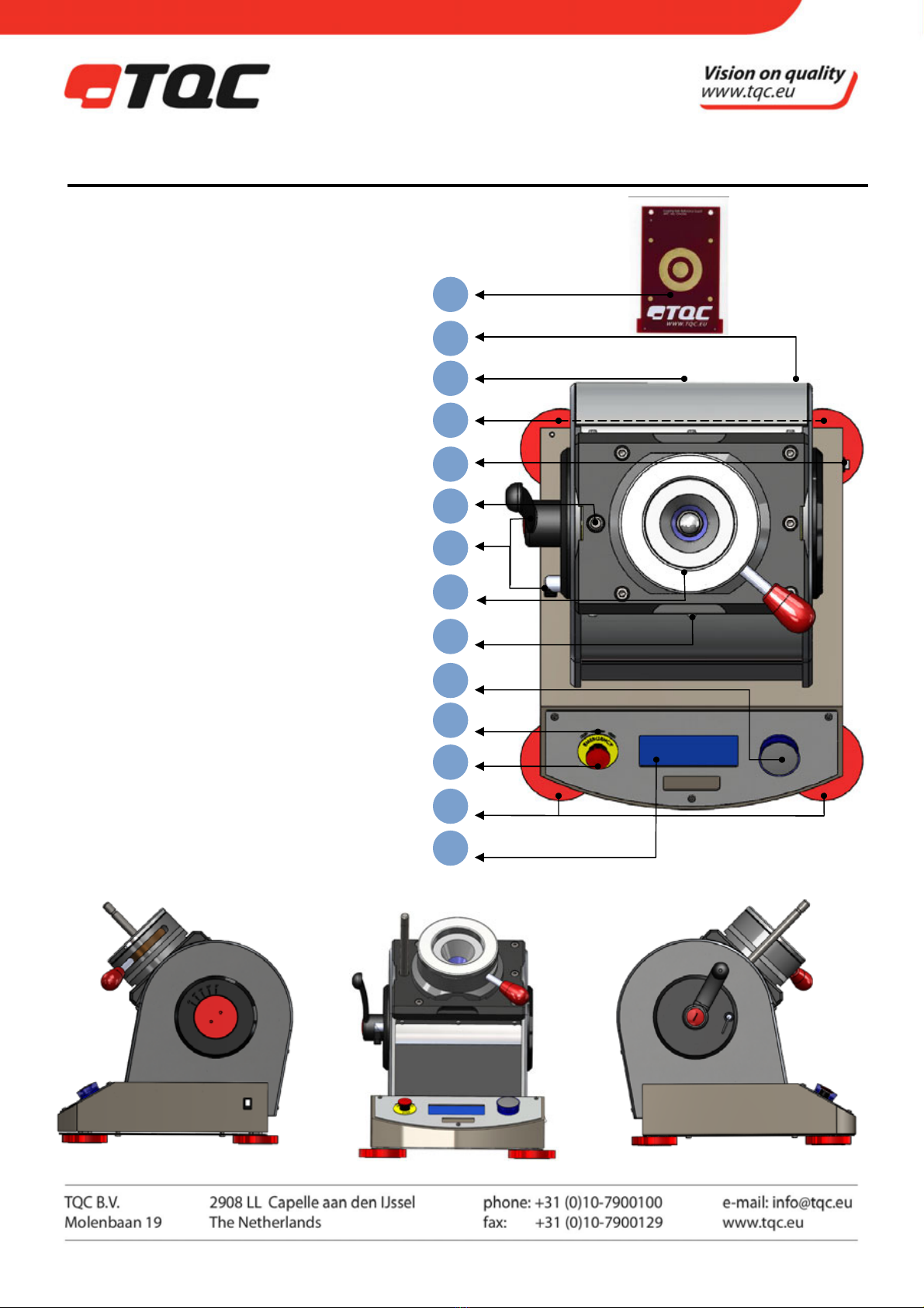
6INSTRUMENT CONTROLS AND FUNCTIONS
1. Display with process information
2. Jog Shuttle
3. Emergency button
4. Acoustic alarm / Buzzer
5. Levelling supports
6. Panel clamp with LED ring
7. Brake and lock for Sample holder
8. Mains connection
9. Microscope support rod
10. Calibration plate holder
11. Calibration plate
12. Panel slot
13. ON/OFF Switch
1
5
3
4
2
12
6
7
9
13
5
10
8
11

10
|
7INSTRUMENT PREPARATIONS
When using an optional Loupe or USB microscope please insert the supplied optical tool fixture rod in de
designated hole according to the instruction manual.
7.1 Test Panels
We supply a range of test panels
In aluminum or steel in different sizes.
All with a protective PE film.
For more details go to http://www.tqc.eu/en/products/article/615/KNOCK-OUT-TESTPANELS
7.2 Calibration plate
The TQC Automatic cupping test is supplied with the CP4306 Cupping Test reference board. This specially
designed calibration tool is stowed on the rear of the TQC Automatic Cupping test. This precision engineered
reference board allows the user to calibrate the TQC Automatic Cupping Test at custom set intervals.
7.3 Optical tool fixture rod
Insert the Optical tool fixture rod with side with the length groove first into the designated hole in the cupping
test. After insertion turn the tool either direction untill it clicks into place.
7.4 Panel clamp
The sample panels are clamped by means of the red handle. This handle is moved backwards to release the
panel and to the front to fix the panel.
7.5 Moving the Sample holder
The sample holder is locked into place by means of the little steel locker on the left site with the fan pointing
down and against the Aluminium housing of the cupping tester the sample holder is locked at the given angle.
The black handle functions as a brake. To lock the sample holder vibration free into place.
8MENU DISPLAY INFORMATION AND OPERATION
8.1 TQC Start screens after switched on.
Switch on instrument by mains switch at the right side on the
housing.
This is the first screen shown after switching on the instrument.
After a few seconds the time and date screen appears showing
the time left till next calibration. When a calibration is required
the TQC Automatic cupping test will inform the user that
calibration is required in this screen. The linguistic warning is
also accompanied with audio warning.
Every time the TQC Automatic Cupping test is turned on. The
indenter needs to find its reference positions. Press the jog
shuttle to activate the reference procedure..

11
|
8.2 MAIN MENU
The TQC Automatic Cupping Test has an advanced menu
structure. The Main Menu allows the user to access all the
features available. To select a function turn the Jog shuttle till
the white selector is on the item and push the Jog shuttle.
8.3 RUN SETUP
The TQC Automatic cupping test is able to operate in two
modes. Manual test can be performed to determine when
cracks start to appear and allow the user to start and stop the
movement of the indenter at his or her discrepancy. When the
Preset test modes is selected the indenter will stop at a set
depth
8.3.1 RUN SETUP – Preset test.
When Preset test is selected two new options will appear. The
“Stop at” to set the depth on which the indenter should stop,
and the Auto return option. The last determines if the indenter
should automatically return to its base position after the set
depth is reached. When used on substrates that are elastic or
tend to want to recover to their initial shape the Auto return
option is best turned off.
8.4 LIGHT SETUP
One of the most innovative features of the TQC Automatic
Cupping Test is its ability to produce any colour of light to
illuminate the test surface. Not only enhancing the visibility
but also significantly reducing operator strain. Either one of
the six preset colours (Red, Green, Blue, Yellow, White and
Warm White) can be selected or the colour can manually be
selected by setting the RGB value’s.
The intensity setting lets you set the strength of the light. The left and right check boxes allow you to set the
direction of the light. Cracks can best be seen when the complementary colour to the test panel is used to
illuminate the panel .
8.5 INSTRUMENT SETUP
The instrument setup menu gives the user access to more
advanced settings allowing him or her to fine tune the
instrument to their specifications.

12
|
8.6 INSTRUMENT SETUP – INDENTER SPEED
The TQC Automatic Cupping Test is able to operate at speeds
from 0.01 mm/s up to 0.70mm/s. The speed can be set in 0.01
mm/s increments. The Nominal speed according to the ISO
1520 is 0.20 mm/s. To set the speed select the speed by
pushing the Jog Shuttle and then set it by turning the Jog
shuttle. When the desired value is reached push the Jog
Shuttle to set the speed.
8.7 INSTRUMENT SETUP – DEPTH SIGNAL
When operating in manual mode the user only wants to look at
the test panel and should not have to look at the display in
order to know how far the indentation is. This problem is solved
by setting up the Depth signal menu. The TQC Automatic
Cupping Test can give visual and audible warnings at set depth
intervals. Setting the tick mark will enable the warning. The
increments of the warnings can be set with the increment
option. Audible alarm will be a short beep and the visual a
change in light intensity.
8.8 INSTRUMENT SETUP – SETUP TIME/DATE
The TQC Automatic Cupping Test contains a real time clock to
store the time and date with each calibration. Also the time and
date are used for setting the calibration interval. In this menu
the time and date can be set by selecting the desired figure and
pushing the jog shuttle to edit the number. The TQC Automatic
Cupping Test has no daylight savings correction built-in. It
should be adjusted manually at these times.
8.9 INTRUMENT SETUP – UNITS
The units used in the display can be set to one of the three
available units. The selected unit will be displayed in all other
menu’s.
8.10 INSTRUMENT SETUP – ACOUSTICS
The audible alarm levels can be set in this menu. The three
available options are no sound, low volume or high volume.
When Signals off is selected the audible alarm for depth
indication will also not be heard.
8.11 INSTRUMENT SETUP – LANGUAGE
The TQC Automatic Cupping Test is equipped with a multi
language menu. In this part of the menu you can select the
desired language. Set the tick mark in front of the desired
language.
13
|
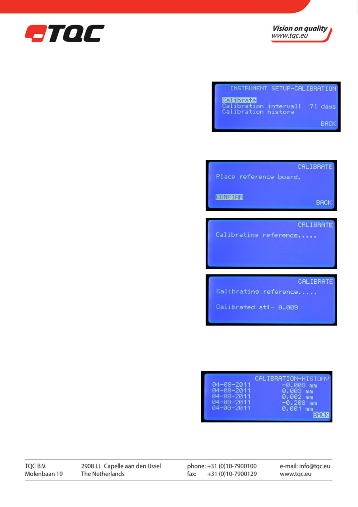
8.12 INSTRUMENT SETUP – CALIBRATION
One of the most innovative features of the TQC Automatic
Cupping Test is the highly advanced calibration method,
allowing the user to calibrate with micrometer accuracy. The
Calibration Menu allows the user to access all features
relevant to calibration. Calibrate let’s the user perform the
calibration, while calibration interval let’s you determine the
interval with witch the cupping test needs to be recalibrated.
The interval can only be set in full days.
8.13 CALIBRATE
After calibration is selected in the calibration menu the TQC
Automatic Cupping Test asks for the reference board to be
inserted. Take care that the reference board is free of
contamination at all times. Place the board from either side of
the Sample holder into the panel slot until the stoppers at the
TQC logo side. When the reference board is inserted lock it in
place with the panel clamp handle. Select confirm to verify
that the reference board is in place.
The TQC Automatic Cupping test new starts to search for the
calibration plate. By slowly moving the indenter towards the
plate. This can take several seconds for the calibration to be
finished. While the calibration is in progress Calibrating
reference…. is shown.
When the Calibration is finished the Cupping test shows the
offset of the TQC Automatic Cupping Test. Now the calibration
is finished and the cupping test is the most accurate available.
Normally the offset will be low. High offsets can occur when
the cupping test had been turned of while performing an
indentation or when turned on after transport.
8.14 CALIBRATION – HISTORY
The TQC Automatic Cupping Test stores the last 5
calibrations. Date and Calibration value are recorded. The
top value is the latest.
14
|
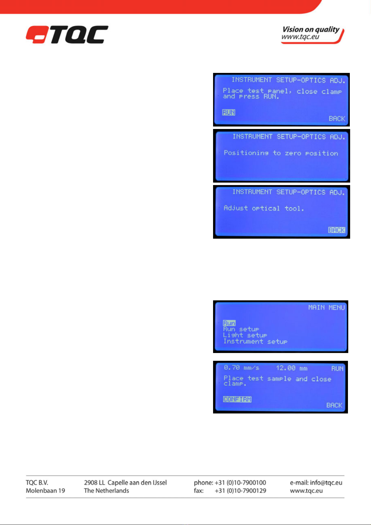
8.15 INSTRUMENT SETUP – OPTICS ADJ.
The unique design of the TQC Automatic Cupping Test allows
the user to use optional available loupe or USB microscope.
The latter has a limited depth of focus and needs to be
adjusted to zero level. In its base position the indenter is about
0.5mm below the test panel. An USB microscope can only be
adjusted when the indenter is against the test panel. In order
to bring the indenter to its zero position the optical
adjustment menu can be used.
When the TQC Automatic Cupping Test informs you to adjust
the optical tool you are able to adjust the camera. Always
adjust the camera on the panel you are planning to do your
tests on. The thickness of a panel and coating will influence
your focus. Select back for the indenter to move back to their
base position.
In the base position both the indenter and the camera focus
are 0.5mm below the panel. The camera support is not fixed
to one position. It moves along with the indenter to keep
your camera focussed on the top of the indentation,
allowing you to always have a perfect picture.
8.16 RUN
When performing a run the displayed screens vary depending
on the in “Run setup” selected type of run. Both run menu
types will be explained in the next two paragraphs.
8.17 PRESET RUN
In the first screen the TQC Automatic Cupping Test asks the
user to place the test panel and close the clamp. When done
select confirm to continue.

15
|
The actual position of the indenter is shown. Press run for the
test to start. The top of the screen will show the set speed and
depth. During the test “stop” can be selected to stop the test
and have the indenter return to base position.
After the test has been completed depending on the auto
return setting the indenter automatically returns to base
position or after conformation by pressing back.
8.18 MANUAL RUN
During manual run only the set speed is shown in the top of
the screen. The sample placement steps are the same as
during the preset test. In this case only the jog shuttle needs to
be selected ro run and needs to be hold. Releasing the jog
shuttle will stop the indenter from moving. Pressing the
shuttle again at run will continue the test. At the end of the run
pressing back will bring the indenter back to its base position.
8.19 Warning signals
Due to circumstances the display shows:
“Release the Emergency knob” Caused by manually pressing of the Red emergency
button. Check the fault or wrong handling.
”Place test sample and close clamp.” Is shown the panel is not placed correctly or the clamp is not tightened
enough. Replace the test panel and close the clamp

16
|
9OPERATION
9.1 Preparatory Work
•Connect the instrument to the mains at the rear side of the housing.
•When using a loupe or microscope insert the fixture rod according to illustrations.
•Adjust Test cylinder such that good visibility of the test surface is guaranteed.
9.2 Performing a Cupping
For performing a cupping test a suitable panel is required. Please see the specifications and required standards
for further specifications.
9.3 Start the instrument
Start the instrument following the steps listed in Section 8.
10 CARE AND MAINTENANCE
10.1 Inspection and Maintenance
•Though robust in design, this instrument is precision-machined. Never drop it or knock it over.
•Always clean the instrument after use.
•Clean the instrument using a soft dry cloth. Never clean the instrument by any mechanical means such as a
wire brush / abrasive paper. This may cause, just like aggressive cleaning agents, permanent damage.
•Do not use compressed air to clean the instrument.
•Never touch the indenter with bare hands. Grease from your hand may reduce electrical contact and cause
the indenter to falsely locate.
•Generally the TQC Cupping Test does not require any maintenance.
Make sure that no paint or other liquids are spilled on the electronics or left in the holes.
10.2 Disposal of Materials
Disposal of materials used in the operation of the instrument or for auxiliary functions and exchanged items
should be dealt with safely and in a manner that will not harm the environment. Follow the local regulations.
10.3 Customer Service
Customer service is provided on request by
TQC - Molenbaan 19, 2908LL Capelle aan den IJssel - The Netherlands,
T +31(0)10 7900 100, F +31 (0)10 7900 111
11 DISCLAIMER
The right of technical modifications is reserved.
The information given in this manual is not intended to be exhaustive and any person using the product for any purpose other than that
specifically recommended in this manual without first obtaining written confirmation from us as to the suitability of the product for the
intended purpose does so at his own risk. Whilst we endeavour to ensure that all advice we give about the product (whether in this
manual or otherwise) is correct we have no control over either the quality or condition of the product or the many factors affecting the
use and application of the product. Therefore, unless we specifically agree in writing to do so, we do not accept any liability whatsoever
or howsoever arising for the performance of the product or for any loss or damage (other than death or personal injury resulting from our
negligence) arising out of the use of the product. The information contained in this manual is liable to modification from time to time in
the light of experience and our policy of continuous product development.
Warning
Other manuals for SP4300
1
Table of contents
Other TQC Test Equipment manuals


