Trace2O AquaSafe WSL50 User manual

AquaSafe
WSL50
Water Safety
Laboratory
Instruction Manual

Contents
Section 1: Introduction
Section 2: Kit Contents
Section 3: Double Incubator Instructions
Section 4: Membrane Filtration Instructions
Section 5: Turbidity Tube Instructions
Section 6: Block Tester Instructions
Section 1: Introduction
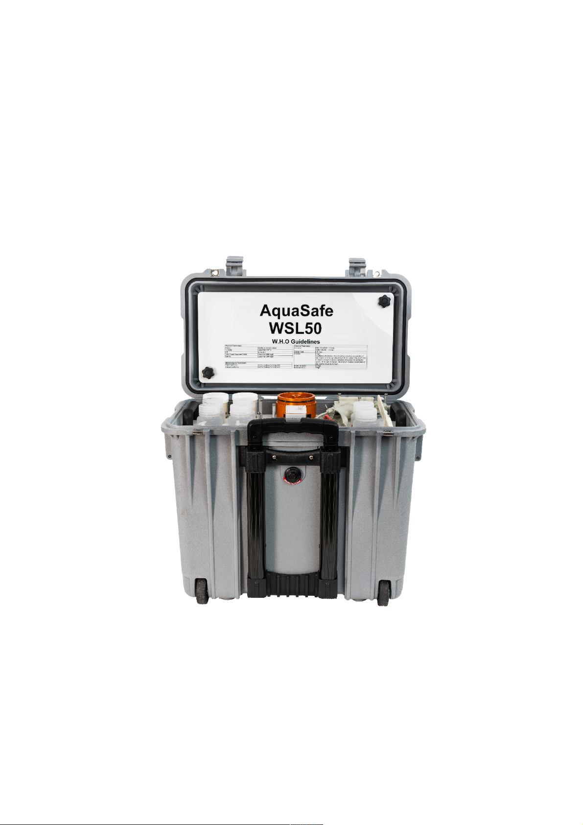
The AquaSafe® WSL50 is a fully portable field laboratory for the detection of microbiological and
physico-chemical water quality parameters.
The lab is housed in a waterproof wheeled carry case with telescopic handle and comprises the
following:
• Integrated dual chamber digital incubator complete with all accessories and consumables for
carrying out 300 tests for Faecal and Total Coliforms.
• Block Tester complete with consumables for 300 tests of Free & Total Chlorine and pH.
• Turbidity Tube for turbidity testing in the range 5 to 500NTU.
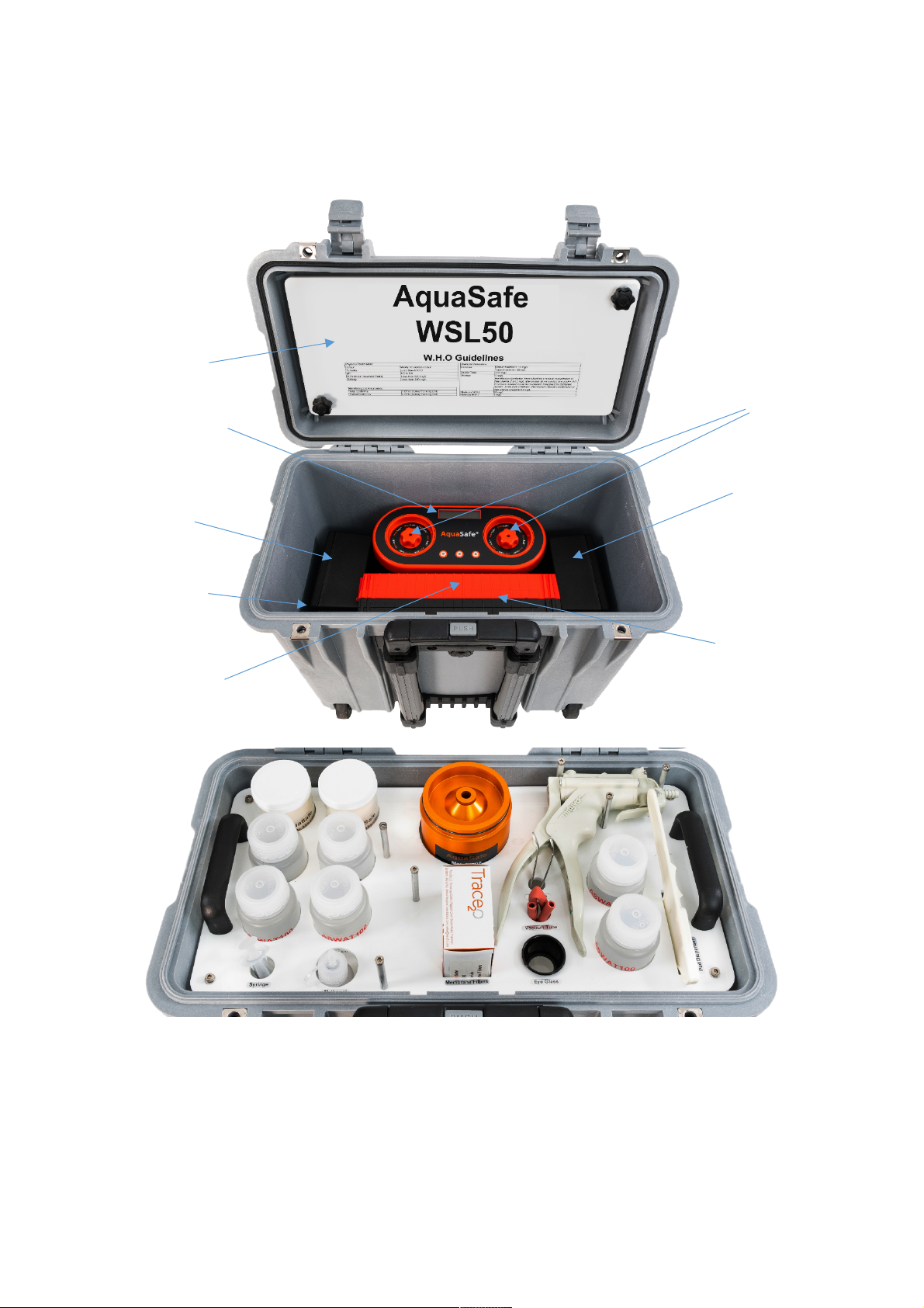
Section 2: Kit Contents
1
2
3
4
5
5
Under Accessories
Box: 6, 7
8
a
b
c
d
e
f
g
h
i
j
k
k
l
b
b
a
b

Main Case Components
Item
Qty
Description
1
1
Sterilisable Work Surface
2
1
AquaSafe® Double Incubator
3
2
PetriLok® Cassette with cap and 25 Aluminium Petri Dishes
4
1
Accessories Box
5
2
Black Box
6
1
Silicone Grease
7
1
Calibration Pack
8
1
5 Metre Sampling Cable with Carabiner
Tray Components
Item
Qty
Description
a
2
Sterile Absorbent Pads (100 Pack)
b
4
Sample Collection Bottles with Dechlorination Tablets
c
1
5ml Sterile syringe
d
1
30ml Dropper Bottle for Methanol
e
1
Membrane Filtration Unit including, waste beaker, sample beaker, measuring
funnel, sintered glass disk & 1 silicone gasket
f
1
Sterile Membrane Filters (100 Pack)
g
1
Forceps
h
1
Vacuum Tube
i
1
Eyeglass
j
1
Vacuum Pump
k
2
Sterilised Water for Membrane Lauryl Sulfate Broth preparation
l
1
Pad Dispenser
Accessories Box Components
Qty
Description
1
Multipurpose Screwdriver
1
Digital Thermometer
6
Membrane Lauryl Sulfate Broth Sachet
1
Nitrate Test Tube
1
Test Tube Brush
1
Vehicle Charging Cable
1
12V 4A Lead Acid Charger/Power Supply

Black Box
Qty
Description
1
IEC Mains Cable - UK
1
UK to EU Adapter
1
Pool Tester
3
HP1 Phenol Red Rapid Tablets (100 Pack)
3
HP2 DPD No.1 Rapid Tablets (100 Pack)
3
HP3 DPD No.3 Rapid Tablets (100 Pack)
Separate Box
Qty
Description
4
Sterilised Water for Membrane Lauryl Sulfate Broth Preparation
2
Sterile Membrane Filters
1
Sterile Absorbent Pads
1
2 Part Turbidity Tube 5-500 NTU
1
Cotton Drawstring Backpack

Section 3:
AquaSafe
Micro-biological
Incubator
Instruction Manual

Contents
1.0 Introduction ..................................................................................................................................... 9
2.0 Incubator set-up ............................................................................................................................ 10
2.1 Docking Station .......................................................................................................................... 10
2.2 Battery Removal ........................................................................................................................ 11
2.3 Battery charging ......................................................................................................................... 11
2.4 Vehicle Power ........................................................................................................................... 12
2.5 Fuse ............................................................................................................................................ 12
3.0 Operating instructions ................................................................................................................... 13
3.1 Incubator controls ...................................................................................................................... 13
3.2 Getting started ........................................................................................................................... 14
3.3 Menu Options ............................................................................................................................ 15
3.3.1 Menu sequence – Left Chamber ......................................................................................... 16
3.3.2 Menu sequence – Right Chamber ....................................................................................... 17
3.3.3 Start screen (Figure 1.1) ...................................................................................................... 18
3.3.4 37°C Program (Fig 1.2) ........................................................................................................ 19
3.3.5 44°C Program (Fig1.3) ......................................................................................................... 20
3.3.6 User defined Program (Fig 1.4) ........................................................................................... 21
3.3.7 Resetting the timer (Fig 1.5) ............................................................................................... 22
3.3.8 Incubation cycle time setting (Fig 1.6) ................................................................................ 22
3.3.9 User defined temperature setting (Fig1.7) ......................................................................... 23
3.3.10 Calibration (Fig 1.8) .......................................................................................................... 24
4.0 Care and Maintenance ................................................................................................................... 25
4.1 General ...................................................................................................................................... 25
4.2 Cleaning ..................................................................................................................................... 25
4.3 Maintenance .............................................................................................................................. 26
5.0 Technical Specification ................................................................................................................... 26
5.1 Docking station: ......................................................................................................................... 26
5.2 Incubator: ................................................................................................................................... 27
6.0 Guarantee and Assistance ............................................................................................................. 27
1.0 Introduction
The AquaSafe® Double Incubator is a portable incubator for the incubation of microbiological
samples prepared using the membrane filtration method. The incubator is primarily designed to
be used with the supplied 54mm x 3.5mm aluminium petri dishes which are suitable for 47mm
membrane filter pads, but the incubator can also be used with 55mm pre-prepared plastic petri-
dishes.
The incubator has two independently controlled chambers, each supplied with 25 Petri dishes as
standard, but have the capacity for more due to the Petri-Lok® system.
The incubator has the option to run 37°C, 44°C and user defined temperature profiles for periods
of 1 – 24 hours.
2.0 Incubator set-up
The incubator is integrated into the waterproof carry case with a docking station which
incorporates the rechargeable battery pack and power supply for the unit. An external charger is
also supplied which is connected to the port on the rear of the case.
The power pack is comprised of a 12V 15.6Ah Sealed Non-Spillable Lead acid battery. The battery
pack must be electrically isolated during transport on-board aircraft. To facilitate this, a switch has
been incorporated in the carry case which isolates the power supply.
Please note when transporting via aircraft the switch must be in the off position (depressed)
and secured such that it cannot become depressed during transit (covering the recessed plate
with rigid card should achieve this).
2.1 Docking Station
The Incubator is mounted on a docking station built into the
carry case, which incorporates the rechargeable battery pack
and allows the incubator to be run from the batteries during
transportation. It is also possible to use the incubator on a
bench independent of the dock if desired, as long as it is
connected to a 240 V AC outlet via the cables provided.
To remove the incubator from the docking station, lift the
incubator vertically upwards, ensuring not twist or tilt the
incubator as this could result in damage to the connectors. To
place the incubator back onto the docking station, centre the
incubator left to right on the docking station with the front
edge against the foam, then push down into position.
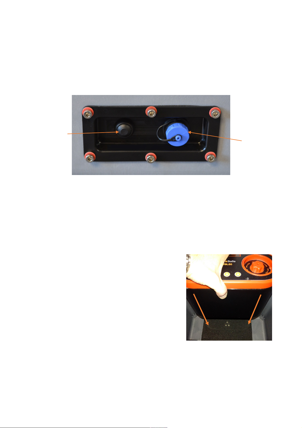
On/Off
Switch
Charger
Connection

2.2 Battery Removal
It may be desired to remove the batteries or replace them at the end of their life. To replace or
remove the batteries first ensure the switch on the rear of the carry case is in the off position then
remove the screw on the left side of the docking station.
Next lift up the hinged panel from left to right which will reveal the two batteries. To remove the
batteries lift each battery out carefully and disconnect the wires from the battery terminals.
Replacement is the reversal of removal. Ensure that the brown wires go to the red terminals and
that the blue wires go to the black terminals. Failures or damage arising due to incorrect
connection of the wires will invalidate the warranty. It is also advised that batteries are only
removed if absolutely necessary.
2.3 Battery Charging
It is recommended to charge the battery fully prior to use. To do this remove the power supply
unit from the kit and connect it to the charging connection on the rear of the carry case, screwing
firmly into position. Plug the other end into a 90 - 240V AC outlet, then switch on the unit via the
on/off switch on the read of the case.
The indicator on the charger will illuminate red, orange or green. The states indicate battery
condition as follows:
Red: discharged.
Orange: Partially charged.
Green: Fully charged.
To charge the battery from a discharged state takes approximately 4-6 hours.
If desired the incubator can be used whilst the battery is being charged however the battery will
charge at a lower rate.
Note: The battery charger comes complete with an IEC C19 to UK mains lead. Replacement leads
must be of the same type with a sealed plug and maximum cable length of 2 metres, and must
carry the CE mark.
Screw
Batteries

2.4 Vehicle Power
The incubator is also supplied with a vehicle cigarette lighter cable. This cable can either be
plugged into the socked on the rear of the carry case or into the incubator on the rear of the unit.
Then plug the cigarette lighter plug into the cigarette lighter socket in the vehicle. 12V or 24V
vehicle systems may be used. Note that the internal battery will not charge while connected to
the vehicle. It is advised that the vehicle’s engine should be running for the majority of the period
of time that the incubator is used to prevent discharge of the vehicle battery. Alternatively an
auxiliary battery may be used. (Cable available separately)
Note: The vehicle cigarette lighter charging lead is a specialist product and as such only a
genuine Trace2o® replacement should be used. Replacements are available from any Trace2o®
approved representative.
No attempt should be made to charge or power the equipment other than via the approved
Trace2o® equipment.
2.5 Fuse
The docking station contains a fuse to protect the incubator in the unlikely event of a short circuit
or thermal runaway. In the event of fuse failure the fuse may be replaced, provided the cause of
the fault is identified and rectified.
To replace the fuse, locate the fuse holder in the battery compartment as illustrated below:
Unscrew the fuse holder and remove the fuse. Replace with the same type (only as specified in
section 5.1) and screw the fuse holder back together.
Fuse
Holder

3.0 Operating instructions
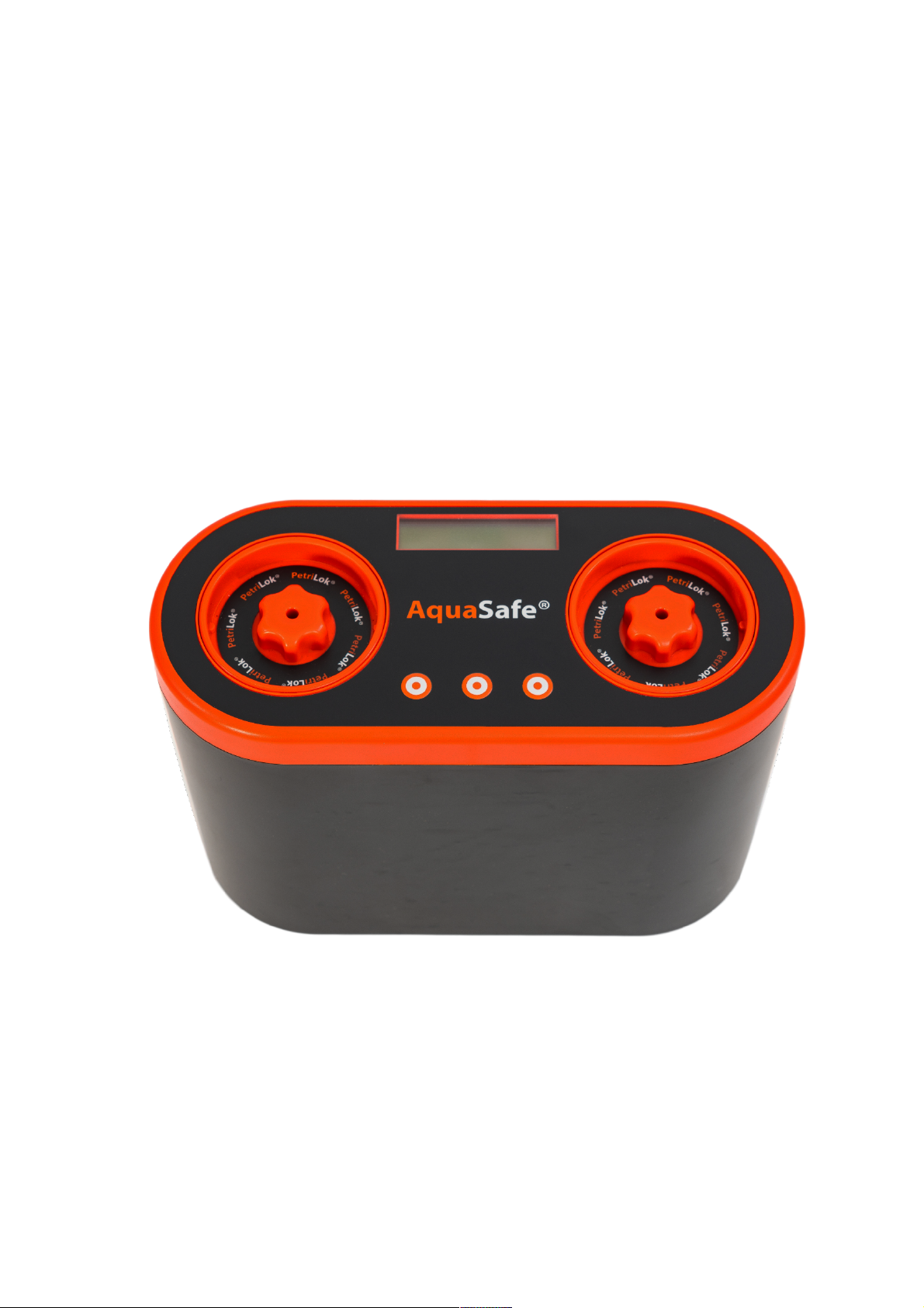
3.1 Incubator controls
Petri-Lok® cassette
Switches
LCD Display
Petri-Lok® Cassette.
The Petri-Lok® cassette consists of a
rack and a spring loaded top to hold the
petri-dishes in place. To remove the
cassette twist the cassette to the left
and lift out. The top of the cassette is
removed by pushing down on the top
whilst holding the rack, twisting to the
left and then removing the top. To re-
fit align the arrow with either of the
two slots in the top of the rack, push
down and twist lock into place.
The incubator has a power connection
socket on the rear of the unit and three
switches on the top which control all
functions of the incubator.
The incubator can be run from a power
supply in the range 12 – 24 Volts.
All information is displayed to the user
via the LCD display on the top of the
unit.

3.2 Getting started
Instructions for membrane filtration are covered in another section of the kit manual.
The user should familiarise themselves fully with the set-up, control and calibration of the
incubator prior to carrying out tests for the first time.
If the incubator is connected to the docking station turn on using the switch on the rear of the
carry case. If connected directly to the power supply turn on the power at the AC mains outlet.
The incubator screen will turn on.
The incubator may be in one of three operating modes on power up:
1: New run
2: Partial incubation cycle (Idle)
3: Partial incubation cycle (Run)
If the incubator is in mode 1 or 2 the screen shown in Fig 1.0 (see page 8) will be displayed. If the
incubator is in mode 3 the incubator will return to the last know state and auto start the
incubation cycle from where it was before the power was removed. Mode 3 is primarily intended
for unattended power failure conditions.
If Fig 1.0 is displayed and the incubator was in mode 2 then the previous incubation cycle can be
restarted from where it was left by pressing restart. This will be discussed later.
The screen will be displayed for 60 seconds before defaulting to the restart condition.
Pressing the right hand switch will reset the incubator ready to set-up and start a new incubation
cycle and the screen will change to the one shown in Fig 1.1 (see page 8).
The incubator has two independently controlled thermal chambers which can be configured and
calibrated independently.
The left hand switch primarily selects the mode for the left hand chamber and the right hand
switch the mode for the right hand chamber. The centre switch will perform selections for each
side which will be indicated by an arrow pointing left or right < >.
Each screen and options will now be discussed in further detail.

3.3 Menu Options
The incubator is a menu driven system. In section 3.3.1 and 3.3.2 the menu sequences will be
outlined. In section 3.3.3 onwards the detailed instructions for each screen will be described for
the left chamber. The operation of the right chamber is exactly the same except that the right
hand switch will be used to step through the sequence instead of the left. As such the functions of
the right chamber will not be described in detail.
It should be noted that each chamber can be run with a different setting as they are independent
of each other, however when the incubator is in run mode changes cannot be made to the
settings of either chamber. To make changes to the setting of one or both chambers the user will
need to exit run mode. This is to prevent accidental changes to an incubation cycle which may
cause the test to fail.

3.3.1 Menu sequence – Left Chamber
Once the user has selected Restart or NewRun pressing the left switch will step through the
following sequence. Where an arrow is shown to the left of the middle command the middle
switch will select this action for the left chamber.
The bottom right of the display will show the current state of the right chamber, OFF is shown for
illustration purposes only.
20.9°C 20.9°C
OFF MEM OFF
Select Option
Restart NewRun
20.9°C 20.9°C
->37° MEM OFF
20.9°C 20.9°C
->44° MEM OFF
20.9°C 20.9°C
U->##° MEM OFF
20.9°C 20.9°C
New <SEL OFF
20.9°C 20.9°C
Cal <ADJ OFF
20.9°C 20.9°C
U->##° <ADJ OFF
20.9°C 20.9°C
Tim <ADJ OFF
Fig 1.0
Fig 1.1
Fig 1.2
Fig 1.3
Fig 1.4
Fig 1.5
Fig 1.6
Fig 1.7
Fig 1.8
3.3.2 Menu sequence – Right Chamber
Once the user has selected Restart or NewRun pressing the right switch will step through the
following sequence. Where an arrow is shown to the right of the middle command the middle
switch will select this action for the right chamber.
The bottom left of the display will show the current state of the left chamber, OFF is shown for
illustration purposes only.
20.9°C 20.9°C
OFF MEM OFF
Select Option
Restart NewRun
20.9°C 20.9°C
OFF MEM ->37°
20.9°C 20.9°C
OFF MEM ->44°
20.9°C 20.9°C
OFF MEM U->##°
20.9°C 20.9°C
OFF SEL> NEW
20.9°C 20.9°C
OFF ADJ > Cal
20.9°C 20.9°C
OFF ADJ> U->##°
20.9°C 20.9°C
OFF ADJ> TIM
Fig 1.9
Fig 1.10
Fig 1.11
Fig 1.12
Fig 1.13
Fig 1.14
Fig 1.15
Fig 1.16
Fig 1.17

3.3.3 Start screen (Figure 1.1)
This screen shows the current status of the incubator.
In the state shown the incubator is in idle mode and not running in either chamber.
20.9°C 20.9°C
OFF MEM OFF
Left Chamber
Temperature
Right Chamber
Temperature
Left Chamber
Status
Right Chamber
status
Mode

3.3.4 37°C Program (Fig 1.2)
This mode is the pre-programmed default 37°C incubation cycle. In this mode the incubator will
run an 18 hour incubation cycle at 37°C. The timer can be altered to any setting between 0 and 24
hours. Adjusting the incubation time is described in section 3.3.8.
Pressing and holding the middle switch for 5 seconds will start the incubation cycle and the display
will change to the following:
The asterisk preceding the temperature will switch on and off indicating the status of the heater.
To stop or pause the incubation cycle press and hold the middle switch again for 5 seconds. The
display will show the following:
Pressing and holding the middle switch will restart the cycle or pressing the left switch will return
to the menu function screen.
During the run mode a short press of the middle switch will indicate the battery voltage. For best
accuracy always check the battery voltage when the heater is off (when the asterisk is not
displayed).
Once the chamber has reached the pre-set temperature the timer will start to countdown. If for
any reason the temperature should drop, such as power failure, the timer will auto pause until the
temperature is back to the pre-set temperature. It should also be noted that if there is a power
failure the timer will reset back to the nearest hour. So a reset at 17:35 would result in a reset to
17:00.
The timer displayed is a countdown timer so it will display the time left not the elapsed time.
When the timer reaches 00:00 a buzzer will sound intermittently and the display will display done
A where A is the left chamber.
20.9°C 20.9°C
->37°C MEM OFF
*20.9°C 20.9°C
18:00 RUN! 24:00
*36.9°C 20.9°C
18:00 MEM 24:00

3.3.5 44°C Program (Fig1.3)
This mode is the pre-programmed default 44°C incubation cycle. In this mode the incubator will
run a 24 hour incubation cycle at 44°C. The timer can be altered to any setting between 0 and 24
hours. Adjusting the incubation time is described in section 3.3.8.
Pressing and holding the middle switch for 5 seconds will start the incubation cycle and the screen
will change to the following:
The asterisk preceding the temperature will switch on and off indicating the status of the heater.
To stop or pause the incubation cycle press and hold the middle switch again for 5 seconds. The
display will show the following:
Pressing and holding the middle switch will restart the cycle or pressing the left switch will return
to the menu function screen.
20.9°C 20.9°C
->44°C MEM OFF
*20.9°C 20.9°C
24:00 RUN! 24:00
*43.9°C 20.9°C
18:00 MEM 24:00
Table of contents
Other Trace2O Safety Equipment manuals


Popular Safety Equipment manuals by other brands


Classic Accessories
Classic Accessories Over Drive 79720 instructions

brigo
brigo 23670110 user manual

Petzl
Petzl I'D S Series quick start guide

Kapriol
Kapriol 32560 Instruction and Information Manual

schmersal
schmersal AES 1235 operating instructions

ClimbTech
ClimbTech Freetech HARNESS-XXX-FRT instruction manual