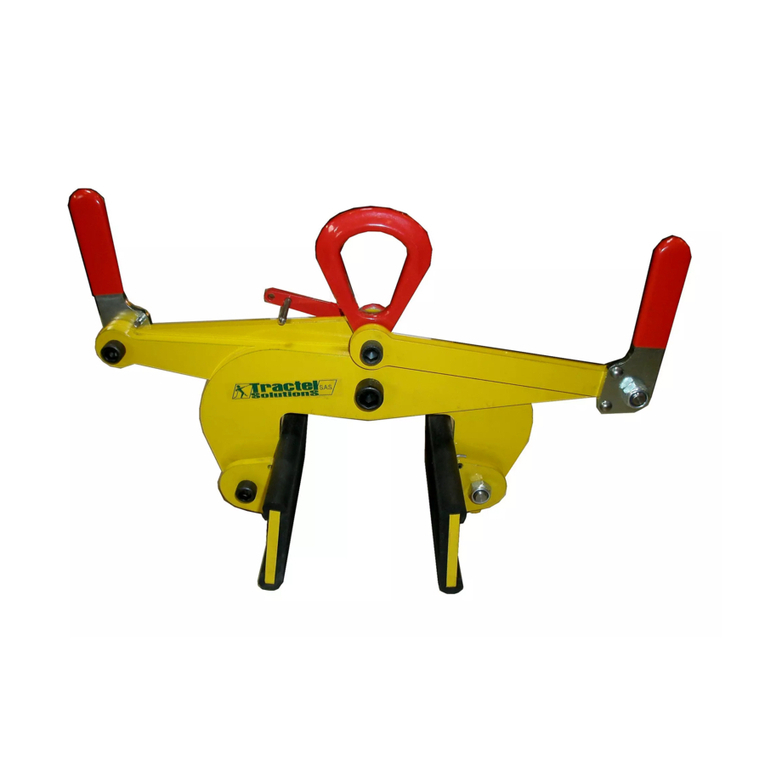
Tractel Corso LT-1B Specification sheet

corso™
Mounting clamps for man riding application
Trägerklemmen für den Personentransport
Pinces poutrelles pour le transport des personnes
Dragerklemmen voor personentransport
Original Operation and
Installation Manual
Manuel d´installation et de
manutention original
Original-Montage- und
Betriebsanleitung
Originele montage- en
bedieningshandleiding

corso™
EN-DE-FR-NL–II G940.8 - 01/2021
Technical Data / Technische Daten / Données techniques / Technische gegevens
Fig./Abb./Fig./Afb. 1
Maximum working load /
Maximale Betriebslast /
Capacité de charge maximale
de fonctionnement /
Maximale bedrijfslast
Weight / Gewicht /
Poids / Gewicht
T A a B C D E F G H J α; β
t kg mm º
LT-1B 1 4,80 75….235 225 25 180….380 76 4 210 155….190 30 45 24 α=±10; β=0
α=0; β=±10
α=±5;
β=±5
LT-2B 2 5,60 75….235 225 25 180….380 84 6 210 155….190 30 45 24
LT-3B 2,5 11,0 95….335 320 23 230….500 114 8 260 215….275 43 60 39
LT-5B 3 12,3 95….335 320 23 230….500 122 10 260 215….275 43 60 39
LT-10B 7 21,0 95….345 315 21 255….515 160 12 280 250….315 60 90 40 α=±5; β=0
α=0; β=±5
α=±5;
β=±5
Table/Tabelle/Tableau/Tabel 1

corso™
G940.8 - 01/2021 EN-DE-FR-NL–III
Components / Bestandteile / Composants / Bestanddelen
Fig./Abb./Fig./Afb. 2
Fig./Abb./Fig./Afb. 3 Fig./Abb./Fig./Afb. 4

corso™
EN-DE-FR-NL–IV G940.8 - 01/2021
Fig./Abb./Fig./Afb. 5
Fig./Abb./Fig./Afb. 6
Fig./Abb./Fig./Afb. 7

Operation and Installation Manual
G940.8 - 01/2021 EN-1
Contents
1 General ............................................................................... 2
1.1 Terms and abbreviations used in this manual .......... 2
1.2 Symbols used in this manual .................................... 3
2 Safety .................................................................................. 3
2.1 General safety instructions ....................................... 3
2.2 Instructions for the operator...................................... 3
3 Overview............................................................................. 4
3.1 Delivery state ............................................................ 4
3.2 Scope of delivery ...................................................... 4
3.3 Equipment description .............................................. 4
4 Description ......................................................................... 5
4.1 Functional description ............................................... 5
4.2 Components / Modules ............................................. 5
4.3 Technical Specifications ........................................... 5
4.4 Anchoring.................................................................. 5
4.5 Safety equipment ...................................................... 5
4.6 Load limits................................................................. 6
5 Optional accessories......................................................... 6
6 Necessary accessories ..................................................... 6
7 Installation and commissioning ....................................... 6
7.1 Directives and standards .......................................... 6
7.2 Checks to be undertaken before
starting installation .................................................... 6
7.3 Assembly .................................................................. 6
7.4 Commissioning ......................................................... 7
8 Operation............................................................................ 7
8.1 Checking before starting work .................................. 7
8.2 Operation .................................................................. 7
9 Foreseeable misuse .......................................................... 7
10 Dismantling ........................................................................ 8
11 Transport and storage....................................................... 8
12 Maintenance work.............................................................. 8
12.1 Authorized maintenance personnel .......................... 8
12.2 Mandatory inspections .............................................. 8
12.3 Care and maintenance.............................................. 8
12.4 Ordering spare parts................................................. 9
13 Disposal and environmental protection .......................... 9
14 Inspection and logbook ...................................................10
14.1 Commissioning tests (carried out by a specialist)....10
14.2 Troubleshooting (to be undertaken by the operator, a
specialist or authorized maintenance personnel) ....10
14.3 Annual safety inspection (to be undertaken by a
specialist or authorized maintenance personnel) ....10
14.4 Annual safety inspection report ...............................11
15 EU Declaration of Conformity (Extract)..........................12
DANGER!
Risk of injury caused by falling objects, malfunctions,
incorrect usage and incorrect operation!
Failure to follow these instructions:
can result in severe injuries or death,
can result in damage to the equipment.
– Read through this operating manual carefully before you
install and commission this machine.
– Follow the instructions and procedures specified in this
manual in order to ensure safe operation of the equip-
ment.

Operation and Installation Manual
EN-2 G940.8 - 01/2021
1 General
Copyright
The copyright of this instruction manual remains with TRACTEL
Greifzug GmbH.
This instruction manual is intended only for the operators of the
systems described here and their staff. This instruction manual
must be available to the operating personnel at all times. Addi-
tional copies can be obtained on request.
No part of this instruction manual may be reproduced, distributed
or otherwise communicated without the permission of TRACTEL
Greifzug GmbH.
Legal proceedings may be implemented in the case of any in-
fringements.
Manufacturer's address
Sales and service office:
TRACTEL Greifzug GmbH
Scheidtbachstraße 19-21
51469 Bergisch Gladbach, Germany
Postfach 20 04 40
51434 Bergisch Gladbach, Germany
Tel: +49 (0) 22 02 / 10 04-0
Fax: +49 (0) 22 02 / 10 04-50 + 70
TRACTEL Greifzug GmbH reserves the right to make changes to
the product described in this instruction manual as part of their
ongoing product improvement programme.
Customers can obtain documentation about other TRACTEL
products by requesting the documentation from companies within
the TRACTEL Group or service organizations appointed by the
TRACTEL Group. Please visit our TRACTEL website at:
www.tractel.com for further details regarding the hoisting gear
and related accessories; stationary or mobile working platforms
for moving around on the inside and outside of buildings; rigging;
block stops for heavy loads; personal safety harnesses to pre-
vent falls; traction and rope tension measuring equipment, etc.
The TRACTEL Group and its dealer network also provide addi-
tional customer and repair services upon request.
1.1 Terms and abbreviations used in
this manual
The terms used in this instruction manual have the following
meanings:
System / Machine
Pursuant to the Machine Directive 2006/42/EC lifting equipment,
hoisting gear, safety equipment and rigging for lifting are regard-
ed as machines. The term "system" or "machine" also describes
the device in which the unit described here will be fitted.
System manufacturer
The system manufacturer (system planner, system manufacturer,
installer) is the company marketing the system and all of the
required components. The system manufacturer is responsible
for the design, manufacturing, assembly and marketing.
Rigging
Rigging consists of equipment which does not belong to the
hoisting gear and which creates a connection between the carry-
ing means and the load or the carrying means and the load lifting
equipment (e.g. rope loops, round slings, shackles, swivel hooks,
eye hooks, deflection rollers).
Anchoring point
Part of the on-site suspended construction to which the suspen-
sion rope, the safety rope, deflection rollers and the hoisting gear
are anchored separately.
Operating personnel
Personnel who have been trained by the operator to operate the
product and are authorized to operate it.
Operator
The operator is responsible for the correct operation of the sys-
tem / equipment and also for adhering to the maintenance inter-
vals and the undertaking of the service work.
Fall arrest device
A device for stopping the load lifting equipment in the event of
the suspension rope snapping or a malfunction, e.g. drive mal-
function.
Overall suspended load
The overall suspended load is the actual suspended static load,
which is made up of the payload, the load lifting equipment's own
weight, the additional fittings, the wire ropes and the control and
connection cables.
Hoisting gear / machine for lifting loads
Device or equipment consisting of a device with load carrying
means for lifting or transporting loads (e.g. wire rope hoist or wire
rope hoist with rope and swivel hook).
Customer / end customer
The customer or end customer is the system manufacturer's
customer and can also be the operator.
Load lifting equipment
A component or piece of equipment which does not belong to the
hoisting gear, which enables the load to be grasped and which is
attached between the machine and the load or to the load itself,
or is intended to be an integral component of the load. Rigging
and its components are also regarded as load lifting equipment.
Material lifting equipment
Load lifting equipment for material.
Maximum working load
The maximum working load specifies the maximum load the
device is allowed to bear. The maximum working load is speci-
fied on the nameplate.
Payload
The payload is the load that is raised, pulled or held in place by
the device. If reeving is used according to the block and tackle
principle then the payload may exceed the maximum working

Operation and Installation Manual
G940.8 - 01/2021 EN-3
load. The maximum working load must never be exceeded by
using reeving.
Man riding equipment
Lifting equipment for persons. Combined material and man riding
equipment also counts here.
Specialist
An appointed person who has undergone the appropriate training
and who, due to his knowledge and practical experience, is able
to safely perform the required work when provided with the nec-
essary instructions.
Products in contact with the rope
Products in contact with the rope include hoists, deflection roll-
ers, fall arrest devices and other products that the rope runs
through or is in contact with.
Carrying means
The carrying means is equipment connected to the hoisting gear
for attaching load lifting equipment, rigging or loads (e.g. a hook
permanently attached to the suspension rope).
Maintenance personnel
A person appointed by and trained by TRACTEL Greifzug GmbH
with a valid certificate, who is capable of safely performing the
required maintenance, inspection and service work when provid-
ed with the required instructions.
1.2 Symbols used in this manual
DANGER!
Type and source of danger
Result: e.g. death or severe injuries.
– Measures that must be taken to eliminate the danger.
ATTENTION!
Type and source of danger
Result: e.g. equipment or environmental damage.
– Measures that must be taken to eliminate any possible
damage.
Note:
This symbol is not used to indicate safety information but to
indicate information that
will give you a better understanding of
the working procedures.
This symbol identifies devices for
transporting
people and materials.
2 Safety
2.1 General safety instructions
DANGER!
Danger of severe injuries caused by malfunctions, incor-
rect use and incorrect operation!
– You must abide by the following instructions in order to
ensure safe operation and correct functioning of the
equipment!
– Please observe the special safety instructions for all of
the work to be performed as described in the individual
chapters in this manual.
– Never use faulty or damaged products, accessories or
rigging.
– Abide by the instructions concerning transport, storage and
cleaning listed on page 8.
– You must abide by the safety specification sheets issued by
the manufacturer of the lubricant being used.
– The anchoring devices must comply with the instructions
given in this manual or the applicable directives / standards.
– The permitted working load must never be exceeded.
– Maintenance and repair work must only be undertaken by
authorized service personnel, see '12.1 Authorized mainte-
nance personnel' on page 8.
– Only qualified personnel who have been trained on the
system are permitted to install and operate it in compliance
with the instructions given in this instruction manual.
– Private users are obliged to obtain training in the assembly,
operation and maintenance of the unit by TRACTEL
Greifzug GmbH.
– Never stand beneath suspended loads. Cordon off the
dangerous area whenever necessary. Support and secure
caught or jammed loads.
– When performing welding work the national safety and
accident prevention regulations must be observed.
2.2 Instructions for the operator
– If more than one person is entrusted with the tasks men-
tioned above then the operator must appoint a supervisor
who is authorized to issue instructions.
– The operator is also responsible for preparing clear operat-
ing, maintenance, repair and other working instructions and
ensuring that the unit is operated correctly by instructing and
training the personnel in the correct and approved utilization
methods.
– The operator is responsible for the correct operation of the
system as well as for adhering to the maintenance periods
and the undertaking of the service work.
– The operator is obliged to keep inspection and log books
(see '14 Inspection and logbook' on page 10).

Operation and Installation Manual
EN-4 G940.8 - 01/2021
– EU Directive 89/391/EEC applies within the European Un-
ion. You must always abide by your country's national acci-
dent prevention regulations.
– You must provide suitable protective equipment such as
safety gloves, hearing protectors and a fall prevention sys-
tem. Protection against extreme weather conditions (e.g.
sun protection, protection against cold) are also considered
to be part of the personal protective equipment.
– Always ensure that the workplace is sufficiently lighted.
– This instruction manual and the instruction manuals for all of
the accessory parts must be handed out to all of the author-
ized personnel. The documents must be available at all
times.
– As TRACTEL Greifzug GmbH does not know the applica-
tions that the product described here will be used for in the
future, the system operator is therefore committed to inform-
ing their personnel about any new safety instructions as well
as any supplementary maintenance work.
– The product must be installed in accordance with the data
given in this manual. The operator of the system is respon-
sible for suitable slinging options.
– The anchoring devices must comply with the instructions
given in this manual or the applicable directives / standards.
– Safe operation is not guaranteed if non-original spare parts
are used. This applies, in particular, to the use of ropes oth-
er than the specified original ropes approved for the applica-
tion. Guarantee claims against the manufacturer will be in-
validated and this will also invalidate the CE approval for
any product holding this approval.
– Adhere to the permitted temperature range, see Fig. 1.
3 Overview
3.1 Delivery state
The equipment is delivered fully assembled.
3.2 Scope of delivery
Mounting clamp:
Allen-key
Documents:
Original Installation and operating manual
CE Declaration of Conformity
3.3 Equipment description
Authorized utilization
Mounting clamp
Mounting clamps serve as anchoring point for hoisting gear,
deflection rollers or working platforms and work baskets (see
Fig. 4 and Fig. 5). The mounting clamps are attached to the
supports using ‘’ or ‘H’ profiles.
Loads must only be raised or lowered in the vertical direction.
Pulling at an angle is only permitted within the limits specified
Table 1 on page II! See also Fig. 7.
Product purpose
The precise requirements on site are not known by TRACTEL
Greifzug GmbH. The precise intended use will be defined by the
operator or the equipment manufacturer.
Maintenance and repair work must only be undertaken by author-
ized service personnel, see '12.1 Authorized maintenance per-
sonnel' on page 8.
Health and safety requirements
TRACTEL Greifzug GmbH declares that the machine described
in this instruction manual complies with technological safety
standards that were applicable to the equipment in the European
Union when it was launched on the market by the manufacturer.
Commissioning the machine is prohibited until the machine in
which this is installed complies as a whole with the regulations of
the 2006/42/EC Directive, the corresponding national legislation
for implementing the regulations in accordance with national law
and the corresponding declaration of conformity has been is-
sued.
The operator or system manufacturer must perform a risk
evaluation in accordance with Appendix I of the guideline
2006/42/EC for machines for raising loads.
A conformity evaluation process must be run by the operator
or the system manufacturer on machines used for man rid-
ing or man riding and material handling, which come under
Appendix IV No. 17 of Directive 2006/42/EC, in accordance
with Article 12, Paragraphs 3 or 4 of Directive 2006/42/EC.
EN 1808 must also be observed when applicable.
Guarantee and liability exclusions
See '9 Foreseeable misuse' on page 7.
Any use other than that described here will be considered to be
unauthorized. TRACTEL Greifzug GmbH does not accept any
liability for damages resulting from unauthorized use. The opera-
tor must assume sole responsibility in this case. Abiding by all of
the instructions given in this instruction manual, in particular the
installation and maintenance regulations, are also considered
part of authorized use.

Operation and Installation Manual
G940.8 - 01/2021 EN-5
Application areas
The product is suitable for use under the following operating
conditions:
For permanent or temporary installations
For short-term operation
Permitted temperature range see Fig. 1.
DANGER!
Danger of severe accidents!
– Use in areas where there is a risk of explosion is prohib-
ited.
– Use in a corrosive environment is prohibited.1)
– Use in close proximity to open fire or in an extremely hot
environment is prohibited.
1) Corrosion protection in accordance with order specifications
Structural requirements
General information
The structural equipment to be used for attaching the product
must be designed in compliance with the applicable Directives
and standards (see '7.1 Directives and standards' on page 6).
The application's overall suspended load must be taken into
account regarding the design of the suspended construction.
The overall suspended load is the actual suspended static load,
which is made up of the payload, the load lifting equipment's own
weight, the additional fittings, the wire ropes and the control and
connection cables.
Systems for the transport of persons:
Man riding equipment must be equipped with a fall arrest device,
which secures the load, for example, on a safety rope against
falling.
Nameplate and warning signs / application
restrictions
Replace missing or illegible nameplates and warning signs im-
mediately.
See Fig. 6.
Item Name
1 Nameplate
The necessary information can be obtained from the nameplate.
Directives and standards
Applicable directives and standards: See '7.1 Directives and
standards' on page 6.
Product versions covered in the manual
The product versions described in this manual are listed in Ta-
ble 1 on page II.
4 Description
4.1 Functional description
The mounting clamp is attached to the supports using ‘’ or ‘H’
profiles. The clamping jaws on the mounting clamps grip the
flange on the support. The clamping jaws are adjusted to the
flange width of the support using the spindle.
Lifting devices fitted with hooks can be suspended from the
suspension eyes.
4.2 Components / Modules
See Fig. 2.
Item Name
1 Clamping jaw
2 Suspension eye
3 Spindle
a: Spindle shaft
4 Locking screw
4.1 Threaded pin
4.2 Copper disc
Allen-key (no picture)
4.3 Technical Specifications
The technical specifications are listed in Table 1 on page II.
4.4 Anchoring
The mounting clamp is attached to the supports using ‘’ or ‘H’
profiles.
– Note the profile size permitted for the respective mounting
clamp, see Table 1 on page II.
– Observe the maximum working load, see Table 1 on page II.
See also '7.3 Assembly' on page 6.
4.5 Safety equipment
Locking screw
For locking the spindle during operation so that the spindle does
not detach without being noticed, causing the mounting clamp to
fall off.

Operation and Installation Manual
EN-6 G940.8 - 01/2021
4.6 Load limits
DANGER!
Incorrect anchoring! Incorrect usage!
Risk of being injured by falling objects!
The load on the deflection roller, rigging and the anchoring
point increases depending on the arrangement of the hoisting
gear, deflection roller and load!
– The support's minimum breaking strength rating must
exceed the hoisting gear's maximum working load by
fourfold for the given installation situation (see Fig. 7).
– If the lifting equipment is attached directly to the anchor-
ing point (see Fig. 7), the deadweight of all of the line
components and the dynamic rate of strain of the hoisting
gear drive system must be taken into account.
Incorrect anchoring! Incorrect usage!
Pulling at an angle is only permitted within the limits specified
Table 1 on page II!
–Please observe the specifications for the angles α and β,
see Table 1 on page II.
5 Optional accessories
The following accessories can also be purchased:
tirak™motor-driven wire rope hoist
greifzug™hand-operated multi-purpose cable hoist
minifor™motorized cable hoist
tralift™TE electrical chain hoist
bravo™lever hoist
tralift™pulley block
Deflection rollers, adapter
Please directly contact TRACTEL Greifzug GmbH.
6 Necessary accessories
The following accessories, which are not part of scope of deliv-
ery, are necessary to use the product:
Rigging and securing equipment with an adequate minimum
breaking strength (see 'Structural requirements' on Page 5).
Manual or electrical hoisting gear
Other original Greifzug accessories: See '5 Optional accessories'
on page 6.
The operator or the manufacturer of the system is responsible for
selecting and using the accessories in accordance with the local
conditions. You must also abide by any other requirements of the
respectively applicable regulations and standards.
7 Installation and commissioning
7.1 Directives and standards
The machine fulfils the following directives and standards:
Machine Directive 2006/42/EC
EN ISO 12100:2010
Machines for man riding or man riding and material handling
(transport of persons):
EN 1808:2015
The operator or the system manufacturer is responsible for en-
suring that the machine is used within the limits specified in these
instructions. The operator or the system manufacturer must also
observe the directives and standards for the machine in which
the unit will be fitted.
7.2 Checks to be undertaken before
starting installation
Inspecting the installation site
General
– Check if other components obstruct a correct installation.
The installation space must not contain any sharp or edged
components.
– Check to ensure that the deflection roller, the rigging and
the on-site anchoring point all have the necessary minimum
breaking strength, see 'Structural requirements' on page 5.
If hoisting gear is attached directly to the anchoring point
(see Fig. 5) then the dead weight of all line components and
the dynamic proportion of the load from the hoisting gear
drive system must be taken into account.
– Check that the mounting does not cover any nameplates
(see Fig. 6).
Check the components and the accessories
– Check that the components and the accessories are com-
plete (See '3.2 Scope of delivery' on Page 4 and
'4.2 Components / Modules' on Page 5).
– Check for signs of damage.
7.3 Assembly
Requirements
Assembly may only be performed by trained personnel.
The workplace must have adequate lighting.
Two people are needed to install heavy mounting clamps.

Operation and Installation Manual
G940.8 - 01/2021 EN-7
Fit the mounting clamp
See Fig. 3.
– Loosen the screw (1).
Note:
If the screw (1) was unintentionally unscrewed:
– Check whether the copper disc (2) is in the threaded hole
(3).
ATTENTION!
Risk of severe accidents!
If the spindle is difficult to turn although the locking screw has
been loosened then the thread on the spindle is damaged.
– Send the mounting clamp to TRACTEL Greifzug GmbH
for repair.
– Open the clamping jaws (4) with the spindle (5).
– Place the mounting clamp on the support (6).
– Close the clamping jaws with the spindle (5):
Ensure that the clamping jaws only touch the parts of the
flange on the support labelled with arrows. The mounting
clamp must sit firmly on the support without any play.
– Tighten the spindle screw (1).
It must no longer be possible to turn the spindle.
Attach the load
See Fig. 4.
– Attach the hoisting gear’s hook (1) or other rigging (e.g.
shackle) so that the suspension eye (2) points downwards.
You must ensure that the size of the hook (1) fits the sus-
pension eye (2). The safety guard (3) must be closed.
After completing the installation
– Check that everything is ready and then run a functional
check, see '7.4 Commissioning' on page 7.
7.4 Commissioning
Determining operational readiness
– Check the mounting clamp anchoring.
Functional test
– Load the mounting clamp with the permitted load.
– Check for pulling at an angle: Pulling at an angle is only
permitted within the limits specified Table 1 on page II!
– The results must be written in the inspection and log book
(see '14 Inspection and logbook' on page 10).
8 Operation
Personnel must have been trained by the operator in operating
the unit and be authorized to use it.
8.1 Checking before starting work
– Check that everything is ready and then run a functional
check, see '7.4 Commissioning' on page 7.
8.2 Operation
DANGER!
Risk of being injured by falling objects!
The load or load lifting equipment may jam and fall!
– Secure loads against falling.
– Secure loads against twisting.
– Prevent the load from swinging.
– Always watch the load, the load lifting equipment and the
anchoring point.
– If necessary, work with a supervisor.
– Never stand below suspended loads.
– Cordon off the dangerous area whenever necessary.
Risk of falling! Risk of being injured by falling objects!
– Overloading might result in the destruction of the mount-
ing clamp or the hoisting gear!
– Observe the maximum permitted load when loading the
load lifting equipment.
– Look out for obstructions along the traversing path.
– Using the mounting clamps to help pull a load along the
ground is forbidden!
– Pulling at an angle is only permitted within the limits
specified Table 1 on page II! Please observe the specifi-
cations for the angles α and β, see Table 1 on page II.
9 Foreseeable misuse
Guarantee and liability claims for personal injuries and equip-
ment damage will be rejected if they can be traced back to one or
more of the following causes:
Unauthorized use of the product, the accessories or the
carrying means belonging to the product
Installation on a sloping support or supports with racks
Use in potentially explosive or corrosive environments
Attaching the load without using matching or correct hooks
Not adhering to the stipulated maintenance periods
Cleaning with a high-pressure cleaner
Incorrect installation, commissioning, operation, mainte-
nance or repairs
Poor monitoring of the parts and the accessories, which has
resulted in wear occurring

Operation and Installation Manual
EN-8 G940.8 - 01/2021
Carrying out incorrect and unauthorized repairs
Welding the mounting clamp onto the support or welding
parts onto the mounting clamp
Use of non-original spare parts
Alteration of safety device settings
Ignoring measurements and checks that would detect early
signs of damage
Product overloaded
Using the mounting clamp for pulling, loosening or pulling a
load sideways. Pulling at an angle is only permitted within
the limits specified Table 1 on page II!
Deliberately causing a load to swing
Opening the mounting clamp while it supports a load or
when hoisting gear is attached
Using the mounting clamp as the earth plate when welding
Anchoring loads to the mounting clamp in positions other
than the suspension eyes provided for this purpose
Accidents caused by foreign bodies or force majeure
The manufacturer will not accept any liability for damages
resulting from modifications and conversions made to the
products or from the use of non-original parts that have not
been authorized by the manufacturer.
Never use faulty or damaged products, accessories and,
rigging.
The minimum flange width dimension T (see table Table 1
on page II) must not be exceeded.
10 Dismantling
See Fig. 4.
– Lower the load lifting equipment and remove if necessary.
– Loosen the screw (1).
– Open the mounting clamp with the spindle (5).
– Remove the mounting clamp from the support.
Always use suitable transport equipment and get a second per-
son to help you with heavy components.
– Clean the device and put it into storage.
11 Transport and storage
Transport
Ensure that no damage occurs during the transporting.
Always use suitable transport equipment and get a second per-
son to help you with heavy components.
Storage
Store in a dry, dust-free location that has a constant ambient
temperature.
12 Maintenance work
12.1 Authorized maintenance personnel
DANGER!
Risk of falling! Risk of being injured by falling objects!
Mortal danger due to incorrectly performed maintenance and
service work!
Maintenance and service work may only be performed by the
following authorized parties:
– TRACTEL Greifzug GmbH
– Lifting equipment service companies authorized by
TRACTEL Greifzug GmbH
– Service personnel trained and certified by TRACTEL
Greifzug GmbH
12.2 Mandatory inspections
A written certificate is required for the annual inspection and any
exceptional tests. The results must be entered in the inspection
and log book (see '14 Inspection and logbook on page 10).
Prior to every use
Always check to ensure that the device is in an orderly working
condition before use, see '7.4 Commissioning' on page 7.
Annual safety inspection
The safety inspection must be carried out annually.
The safety inspection may only be undertaken by authorized
maintenance personnel, see '12.1 Authorized maintenance per-
sonnel' on page 8. Depending on the usage conditions (e.g.
operation in an extremely dirty environment), an intermediate
inspection may be necessary.
We recommend that the system is tested in our factory by
TRACTEL Greifzug GmbH.
Contact TRACTEL Greifzug GmbH or your supplier with regards
to this test.
12.3 Care and maintenance
Interval Work Implementation
Daily – Check the mounting
– Check for dirt
Operator
Whenever
necessary
– Cleaning
– Grease the spindle
Trained person
appointed by the
operator

Operation and Installation Manual
G940.8 - 01/2021 EN-9
Interval Work Implementation
Quarterly – Visually inspect the
clamping jaws (for cracks,
deformations)
Trained person
appointed by the
operator
6-monthly Visual inspection:
– Condition of the support
Trained person
appointed by the
operator
1 x annually – Safety check Authorized mainte-
nance personnel
12.4 Ordering spare parts
Spare parts lists can be obtained from your supplier or directly
from TRACTEL Greifzug GmbH.
The necessary information for placing the order is located on the
nameplates of the individual components, see Fig. 6. Replace
missing or illegible labels immediately.
13 Disposal and environmental
protection
The equipment is made from recyclable materials. If the equip-
ment is later scrapped, it must be disposed of correctly. The
national versions of the waste legislation directive 2008/98/EC
apply within the European Union.
The manufacturer is obliged to take back and dispose of specific
electrical and electronic components in accordance with Directive
2002/96/EC. The following symbol is used on the nameplate of
such components to identify them:

Operation and Installation Manual
EN-10 G940.8 - 01/2021
14 Inspection and logbook
The operator and/or the authorized responsable person are
obliged to maintain this inspection and logbook.
Depending on the situation, the entries are made and
signed by
the manufacturer, an authorized company, the operator, a spe-
cialist or authorized maintenance personnel.
All incidents must be logged correctly in this book and signed.
This includes, e.g.:
All inspections performed
All maintenance work
Modifications and every incidence of troubleshooting
14.1 Commissioning tests (carried out by a specialist)
Commissioning tests Date:
Comments: Specialist:
(Name)
(Signature)
14.2 Troubleshooting
(to be undertaken by the operator, a specialist or authorized maintenance person-
nel)
No. Faults Faults eliminated Date:
Comments: yes no yes no Name:
Company:
(Signature)
14.3 Annual safety inspection
(to be undertaken by a specialist or authorized maintenance personnel)
Repeated inspection Date:
Comments: Specialist:
(Name)
(Signature)
TEMPLATES! Copy and complete as necessary!

Operation and Installation Manual
G940.8 - 01/2021 EN-11
14.4 Annual safety inspection report
Location: Mounting clamp no.:
Operator: System no.:
Inspection date:
Fault Fault Fault Fault Fault
yes no yes no yes no yes no yes no
1. Mounting clamp
1.1 Visual inspection
1.2 Inspect clamping jaws for cracks and
deformations
1.3 Check the state of the spindle
1.4 Function inspection
Inspector's name:
Signature:

Operation and Installation Manual
EN-12 G940.8 - 01/2021
15 EU Declaration of Conformity (Extract)
The manufacturer hereby declares
TRACTEL Greifzug GmbH
Scheidtbachstraße 19–21 51469 Bergisch Gladbach
represented by
Dipl.-Ing. Philippe Gastineau
General Manager
DECLARATION OF CONFORMITY
that the machine described complies with technological safety standards that were applicable to the equipment in the
EUROPEAN UNION when it was launched on the market by the manufacturer.
APPLICABLE DIRECTIVES AND STANDARDS:
2006/42/EC;
EN1808; EN ISO 12100
DESIGNATION
Mounting clamp
APPLICATION
Transport of persons
MODEL
LT-1B, LT-2B, LT-3B, LT-5B, LT-10B
SERIAL NUMBER
Year of manufacture
from 11.2020
Commissioning the machine is prohibited until the machine in which this is installed complies as a whole with the regulations
of the 2006/42/EC Directive, the corresponding national legislation for implementing the regulations in accordance with
national law and the corresponding declaration of conformity has been issued.
The valid EN 1808 standard must be applied for the PAM in which the machine is installed.
Responsible for the documentation:
Dipl.-Ing. Philippe Gastineau, Tel.: +49 (0) 2202 1004 0
Bergisch Gladbach, date

Montage- und Betriebsanleitung
G940.8 - 01/2021 DE-1
Inhaltsverzeichnis
1 Allgemeines........................................................................ 2
1.1 Verwendete Begriffe und Abkürzungen .................... 2
1.2 Verwendete Symbole................................................ 3
2 Sicherheit ........................................................................... 3
2.1 Allgemeine Sicherheitshinweise ............................... 3
2.2 Hinweise für den Betreiber........................................ 3
3 Übersicht ............................................................................ 4
3.1 Lieferzustand ............................................................ 4
3.2 Lieferumfang............................................................. 4
3.3 Gerätebeschreibung ................................................. 4
4 Beschreibung..................................................................... 5
4.1 Funktionsbeschreibung............................................. 5
4.2 Komponenten / Baugruppen..................................... 5
4.3 Technische Daten ..................................................... 5
4.4 Befestigung............................................................... 5
4.5 Sicherheitseinrichtungen........................................... 5
4.6 Belastungsgrenzen ................................................... 6
5 Optionales Zubehör........................................................... 6
6 Notwendiges Zubehör....................................................... 6
7 Installation und Inbetriebnahme ...................................... 6
7.1 Richtlinien und Normen............................................. 6
7.2 Prüfungen vor Beginn der Montage.......................... 6
7.3 Montage.................................................................... 7
7.4 Inbetriebnahme......................................................... 7
8 Bedienung / Betrieb........................................................... 7
8.1 Prüfungen vor Arbeitsbeginn .................................... 7
8.2 Betrieb....................................................................... 7
9 Vorhersehbarer Missbrauch............................................. 8
10 Demontage ......................................................................... 8
11 Transport und Lagerung................................................... 8
12 Instandhaltung................................................................... 8
12.1 Autorisiertes Wartungspersonal................................ 8
12.2 Erforderliche Prüfungen ............................................ 8
12.3 Pflege und Wartung .................................................. 9
12.4 Ersatzteile bestellen.................................................. 9
13 Entsorgung und Umweltschutz........................................ 9
14 Prüf- und Logbuch ...........................................................10
14.1 Prüfung bei Inbetriebnahme (durch einen
Sachkundigen).........................................................10
14.2 Störungsbeseitigung (durch Bediener,
Sachkundigen oder autorisiertes
Wartungspersonal) ..................................................10
14.3 Jährliche Sicherheitsüberprüfung (durch einen
Sachkundigen oder autorisiertes
Wartungspersonal) ..................................................10
14.4 Prüfbericht zur jährlichen Sicherheitsüberprüfung...11
15 EG-Konformitätserklärung (Auszug)..............................12
GEFAHR!
Verletzungsgefahr durch herabfallende Gegenstände,
Fehlfunktionen, falsche Nutzung und Fehlbedienung!
Beachten Sie diese Anleitung nicht:
können schwerste Verletzungen und der Tod die Folge sein,
können Schäden am Gerät entstehen.
– Lesen Sie diese Anleitung sorgfältig durch, bevor Sie
dieses Gerät montieren und in Betrieb nehmen.
– Beachten Sie die Hinweise und Verhaltensregeln, die für
einen sicheren Betrieb des Geräts notwendig sind.

Montage- und Betriebsanleitung
DE-2 G940.8 - 01/2021
1 Allgemeines
Urheberrecht
Das Urheberrecht an dieser Anleitung verbleibt bei der TRAC-
TEL Greifzug GmbH.
Diese Anleitung ist nur für den Betreiber der darin beschriebenen
Anlagen sowie dessen Personal bestimmt. Diese Anleitung muss
dem Bediener jederzeit zugänglich sein. Weitere Exemplare
können angefordert werden.
Ohne Zustimmung der TRACTEL Greifzug GmbH dürfen keine
Bestandteile dieser Anleitung vervielfältigt, verbreitet oder an-
derweitig mitgeteilt werden.
Zuwiderhandlungen können strafrechtliche Folgen haben.
Anschrift des Herstellers
Verkaufs- und Servicestelle:
TRACTEL Greifzug GmbH
Scheidtbachstraße 19-21
51469 Bergisch Gladbach, Deutschland
Postfach 20 04 40
51434 Bergisch Gladbach, Deutschland
Telefon: +49 (0) 22 02 / 10 04-0
Telefax: +49 (0) 22 02 / 10 04-50 + 70
Die TRACTEL Greifzug GmbH behält sich das Recht vor, im
Zuge der Produktverbesserung jegliche Änderungen an dem in
dieser Anleitung beschriebenen Produkt vorzunehmen.
Kunden können über die Unternehmen der TRACTEL-Gruppe
und die von der TRACTEL-Gruppe autorisierten Instandhalter auf
Anfrage Dokumentationen über andere TRACTEL-Produkte
erhalten: Hebezeuge und deren Zubehör, fest installierte oder
mobile Arbeitsbühnen zur Innen- und Außenbefahrung von Ge-
bäuden, Anschlagmittel, Abfangsicherungen für Lasten, Persön-
liche Schutzausrüstung gegen Absturz, Zugkraft- und Seilspan-
nungsmessgeräte, etc. Besuchen Sie hierfür auch die TRAC-
TEL–Website www.tractel.com.
Die TRACTEL-Gruppe und ihr Händlernetzwerk bieten Ihnen bei
Bedarf zusätzlich Kunden- und Reparaturservice.
1.1 Verwendete Begriffe und Abkürzun-
gen
In dieser Anleitung haben die folgenden Begriffe diese Bedeu-
tung:
Anlage / Maschine
Im Sinne der Maschinenrichtlinie 2006/42/EG gelten Lastauf-
nahmemittel, Hebezeuge, Sicherheitsbauteile und Anschlagmittel
zum Heben als Maschine. Mit Anlage oder Maschine wird auch
die Einrichtung bezeichnet, in die die hier beschriebene Maschi-
ne eingebaut wird.
Anlagenhersteller
Der Anlagenhersteller (Anlagenplaner, Anlagenhersteller, Mon-
tagebetrieb) ist der Inverkehrbringer der Anlage und aller not-
wendigen Komponenten. Der Anlagenhersteller ist für den Ent-
wurf, die Herstellung, den Einbau und das Inverkehrbringen
verantwortlich.
Anschlagmittel
Anschlagmittel sind nicht zum Hebezeug gehörende Einrichtun-
gen, die eine Verbindung zwischen Tragmittel und Last oder
Tragmittel und Lastaufnahmemittel herstellen (z. B. Seilschlau-
fen, Rundschlingen, Schäkel, Wirbelhaken, Ösenhaken, Umlenk-
rollen).
Anschlagpunkt, Aufhängepunkt
Teil der bauseitigen Aufhängekonstruktion, an dem Tragseil,
Sicherheitsseil, Umlenkrollen oder das Hebezeug unabhängig
voneinander angeschlagen werden.
Bediener
Person, die vom Betreiber in die Bedienung des Produktes ein-
gewiesen und mit dem Gebrauch betraut ist.
Betreiber
Der Betreiber ist für den ordnungsgemäßen Betrieb der Anla-
ge/des Geräts sowie für die Einhaltung der Wartungsintervalle
und die Durchführung der Instandsetzungsarbeiten verantwort-
lich.
Fangvorrichtung
Vorrichtung zum Abfangen von Lastaufnahmemitteln bei Trag-
seilbruch oder Störungen, z. B. Versagen des Antriebs der Win-
de.
Gesamt-Hängelast
Die Gesamt-Hängelast ist die auf die Aufhängung einwirkende
statische Last, die sich aus der Nutzlast, dem Eigengewicht des
Lastaufnahmemittels, der Zusatzausrüstung, den Drahtseilen
und den Steuer- und Anschlusskabeln zusammensetzt.
Hebezeug / Maschine zum Heben von Lasten
Gerät oder Einrichtung bestehend aus einem Gerät mit Tragmit-
teln zum Heben oder Transportieren von Lasten (z. B. Seilwinde
oder Seilwinde mit Seil und Wirbelhaken).
Kunde/Endkunde
Der Kunde oder Endkunde ist der Kunde des Anlagenherstellers
und kann gleichzeitig auch der Betreiber sein.
Lastaufnahmemittel (LAM)
Ein nicht zum Hebezeug gehörendes Bauteil oder Ausrüstungs-
teil, das das Ergreifen der Last ermöglicht und das zwischen
Maschine und Last oder an der Last selbst angebracht wird oder
das dazu bestimmt ist, ein integraler Bestandteil der Last zu
werden. Als Lastaufnahmemittel gelten auch Anschlagmittel und
ihre Bestandteile.
Materialaufnahmemittel (MAM)
Lastaufnahmemittel für Material.
Maximale Betriebslast
Die maximale Betriebslast gibt an, mit welcher Last das Produkt
maximal belastet werden darf. Die maximale Betriebslast ist auf
dem Typenschild angegeben.

Montage- und Betriebsanleitung
G940.8 - 01/2021 DE-3
Nutzlast
Die Nutzlast ist die Last, die durch das Produkt gehoben, gezo-
gen oder gehalten wird. Durch Einscheren nach dem Flaschen-
zugprinzip kann die Nutzlast größer als die maximale Betriebs-
last werden. Die maximale Betriebslast darf durch das Einsche-
ren nicht überschritten werden.
Personenaufnahmemittel (PAM)
Lastaufnahmemittel für Personen. Hierzu zählen auch Kombina-
tionen von Lastaufnahmemitteln für Material und Personen.
Sachkundige Person
Eine benannte und entsprechend ausgebildete Person, die durch
ihre Kenntnisse und praktischen Erfahrungen in der Lage ist, mit
den benötigten Anweisungen versehen, die erforderlichen Arbei-
ten sicher auszuführen.
Seilberührende Produkte
Seilberührende Produkte sind Winden, Umlenkrollen, Fangvor-
richtungen und sonstige Produkte, durch die das Seil hindurch-
läuft oder die mit Seilen im Kontakt sind.
Tragmittel
Ein Tragmittel ist eine mit dem Hebezeug verbundene Einrich-
tung zur Aufnahme von Lastaufnahmemitteln, Anschlagmitteln
oder Lasten (z. B. ein mit dem Tragseil fest verbundener Haken).
Wartungspersonal
Eine benannte und von der TRACTEL Greifzug GmbH geschulte
Person mit gültigem Zertifikat, die in der Lage ist, mit den benö-
tigten Anweisungen versehen, die erforderlichen Wartungs-,
Prüf- und Instandsetzungsarbeiten sicher auszuführen.
1.2 Verwendete Symbole
GEFAHR!
Art und Quelle der Gefahr.
Folge: z. B. Tod oder schwere Verletzungen.
– Maßnahmen, mit denen die Gefahr vermieden wird.
ACHTUNG!
Art und Quelle der Gefahr.
Folge: z. B. Sachschäden oder Umweltschäden.
– Maßnahmen, mit denen Schäden vermieden werden.
Hinweis:
Dieses Symbol kennzeichnet keine Sicherheitshinweise, sondern
gibt Informationen zum besseren Verständnis der Abläufe.
Mit diesem Symbol sind Geräte für den Perso-
nen- und Materialtransport gekennzeichnet.
2 Sicherheit
2.1 Allgemeine Sicherheitshinweise
GEFAHR!
Gefahr von schweren Unfällen durch Fehlfunktionen,
falsche Nutzung und Fehlbedienung!
– Beachten Sie folgende Angaben, damit der sichere
Betrieb und die ordnungsgemäße Funktion des Gerätes
gewährleistet sind!
– Beachten Sie auch die speziellen Sicherheitshinweise für
alle auszuführenden Arbeiten in den einzelnen Kapiteln
dieser Anleitung.
– Fehlerhafte oder beschädigte Produkte, Zubehörteile und
Anschlagmittel dürfen nicht eingesetzt werden.
– Beachten Sie die Hinweise für Transport, Lagerung und
Reinigung ab Seite 8.
– Beachten Sie die Sicherheitsdatenblätter der Hersteller der
Schmierstoffe.
– Befestigungsmittel müssen den Angaben in dieser Anleitung
bzw. den gültigen Normen/Richtlinien entsprechen.
– Die maximale Betriebslast darf nicht überschritten werden.
– Instandsetzungs- und Wartungsarbeiten dürfen nur von
autorisiertem Wartungspersonal durchgeführt werden, siehe
'12.1 Autorisiertes Wartungspersonal' auf Seite 8.
– Montage und Bedienung dürfen nur durch geschultes und
eingewiesenes Personal unter Berücksichtigung dieser An-
leitung erfolgen.
– Private Anwender sind verpflichtet, sich durch die TRACTEL
Greifzug GmbH in der Montage, der Bedienung und der
Wartung des Geräts schulen zu lassen.
– Nicht unter schwebenden Lasten aufhalten. Wenn nötig,
Gefahrenbereich absperren. Verhakte oder verklemmte Las-
ten abfangen und sichern.
– Bei Schweißarbeiten sind die nationalen Sicherheits- und
Arbeitsschutzbestimmungen zu beachten (z.B. in Deutsch-
land BGR 159).
2.2 Hinweise für den Betreiber
– Ist mehr als eine Person mit einer der hier beschriebenen
Tätigkeiten betraut, so hat der Betreiber einen Aufsichtfüh-
renden zu bestimmen, der weisungsbefugt ist.
– Der Betreiber ist dafür verantwortlich, klare Bedienungs-,
Instandhaltungs-, Wartungs- und sonstige Betriebsanwei-
sungen bereitzustellen und durch Schulung und Anweisung
des Personals den sachgerechten und bestimmungsgemä-
ßen Betrieb und die sachgerechte Bedienung des Geräts si-
cherzustellen.
– Der Betreiber ist für den ordnungsgemäßen Betrieb der
Anlage sowie für die Einhaltung der Wartungsintervalle und
die Durchführung von Wartungsarbeiten verantwortlich.

Montage- und Betriebsanleitung
DE-4 G940.8 - 01/2021
– Der Betreiber ist verpflichtet, das Prüf- und Logbuch (siehe
'14 Prüf- und Logbuch' auf Seite 10) zu führen.
– Innerhalb der Europäischen Union gilt die EU-Richtlinie
89/391/EWG (in Deutschland die Betriebssicherheitsverord-
nung (BetrSichV)). Die nationalen Arbeitsschutzbestimmun-
gen im Betreiberland müssen beachtet werden.
– Stellen Sie geeignete Schutzausrüstung zur Verfügung, wie
z. B. Schutzhandschuhe, Gehörschutz und Absturzsiche-
rung. Zur persönlichen Schutzausrüstung gehört auch der
Schutz gegen extreme Witterungsbedingungen (z. B. Son-
nenschutz, Kälteschutz).
– Sorgen Sie immer für eine ausreichende Beleuchtung des
Arbeitsplatzes.
– Dem beauftragten Personal müssen diese Anleitung sowie
die Anleitungen der Zubehörteile ausgehändigt werden. Die
Dokumente müssen jederzeit zugänglich sein.
– Da die TRACTEL Greifzug GmbH den späteren Anwen-
dungsfall des hier beschriebenen Produkts nicht kennt, ist
der Betreiber dazu verpflichtet, sein Personal über weitere
Sicherheitshinweise sowie über ergänzende Wartungsarbei-
ten zu informieren.
– Das Produkt muss gemäß den Angaben in dieser Anleitung
montiert werden. Für geeignete Anschlagmöglichkeiten ist
der Betreiber der Anlage verantwortlich.
– Befestigungsmittel müssen den Angaben in dieser Anleitung
bzw. den gültigen Normen/Richtlinien entsprechen.
– Wenn keine Original-Ersatzteile verwendet werden, ist der
sichere Betrieb nicht gewährleistet. Dieses gilt insbesonde-
re, wenn nicht die vorgeschriebenen und für die Anwendung
zugelassenen Original-Seile verwendet werden. Der Garan-
tieanspruch gegenüber dem Hersteller entfällt. Bei Produk-
ten mit CE-Kennzeichnung verliert diese ihre Gültigkeit.
– Beachten Sie den zulässigen Temperaturbereich, siehe
Abb. 1.
3 Übersicht
3.1 Lieferzustand
Die Lieferung erfolgt komplett montiert.
3.2 Lieferumfang
Trägerklemme:
Innen-Sechskantschlüssel
Unterlagen:
Original-Montage- und Betriebsanleitung
CE-Konformitätserklärung
3.3 Gerätebeschreibung
Bestimmungsgemäßer Gebrauch
Trägerklemme
Trägerklemmen dienen als:
Anschlagpunkt von Hebezeugen, Umlenkrollen oder Ar-
beitsbühnen und Arbeitskörben (siehe Abb. 4 und Abb. 5)
Die Trägerklemmen werden an Trägern mit - oder H-Profil be-
festigt.
Die Belastung beim Heben oder Senken darf nur in senkrechter
Richtung erfolgen. Schrägzug ist nur in den in Tabelle 1 auf
Seite II angegebenen Grenzen erlaubt! Siehe auch Abb. 7.
Produktbestimmung
Die genauen bauseitigen Voraussetzungen sind der TRACTEL
Greifzug GmbH nicht bekannt. Der genaue Verwendungszweck
wird durch den Betreiber oder den Anlagenhersteller festgelegt.
Instandsetzungs- und Wartungsarbeiten dürfen nur von autori-
siertem Wartungspersonal durchgeführt werden, siehe
'12.1 Autorisiertes Wartungspersonal' auf Seite 8.
Gesundheits- und Sicherheitsanforderungen
Die TRACTEL Greifzug GmbH erklärt, dass die in dieser Anlei-
tung beschriebene Maschine den technischen Sicherheitsbe-
stimmungen entspricht, die zum Zeitpunkt des Inverkehrbringens
in der Europäischen Union durch den Hersteller für die Ausrüs-
tung gelten.
Die Inbetriebnahme der Maschine ist solange verboten, bis die
Maschine, in welche diese eingebaut wird, als Ganzes den Best-
immungen der Richtlinie 2006/42/EG sowie dem entsprechenden
nationalen Rechtserlass zur Umsetzung der Richtlinie in nationa-
les Recht entspricht und die entsprechende Konformitätserklä-
rung ausgestellt ist.
Für Maschinen zum Heben von Lasten muss durch den
Betreiber oder Anlagenhersteller eine Risikobeurteilung ge-
mäß Anhang I der Richtlinie 2006/42/EG durchgeführt wer-
den.
Für Maschinen zum Heben von Personen oder von Perso-
nen und Gütern, die unter Anhang IV Nr. 17 der Richtlinie
2006/42/EG fallen, muss durch den Betreiber oder Anla-
genhersteller ein Konformitätsbewertungsverfahren gemäß
Artikel 12 Absätze 3 oder 4 der Richtlinie 2006/42/EG
durchgeführt werden. EN 1808 muss bei der Anlagenpla-
nung berücksichtigt werden.
Gewährleistungs- und Haftungsausschlüsse
Siehe '9 Vorhersehbarer Missbrauch' auf Seite 8.
Jede von den hier genannten Angaben abweichende Verwen-
dung gilt als nicht bestimmungsgemäß. Für hieraus resultierende
Schäden haftet die TRACTEL Greifzug GmbH nicht. Das Risiko
trägt allein der Betreiber. Zur bestimmungsgemäßen Verwen-
dung gehört auch das Beachten aller Hinweise aus dieser Anlei-
This manual suits for next models
4
Table of contents
Languages:
Other Tractel Power Tools manuals
