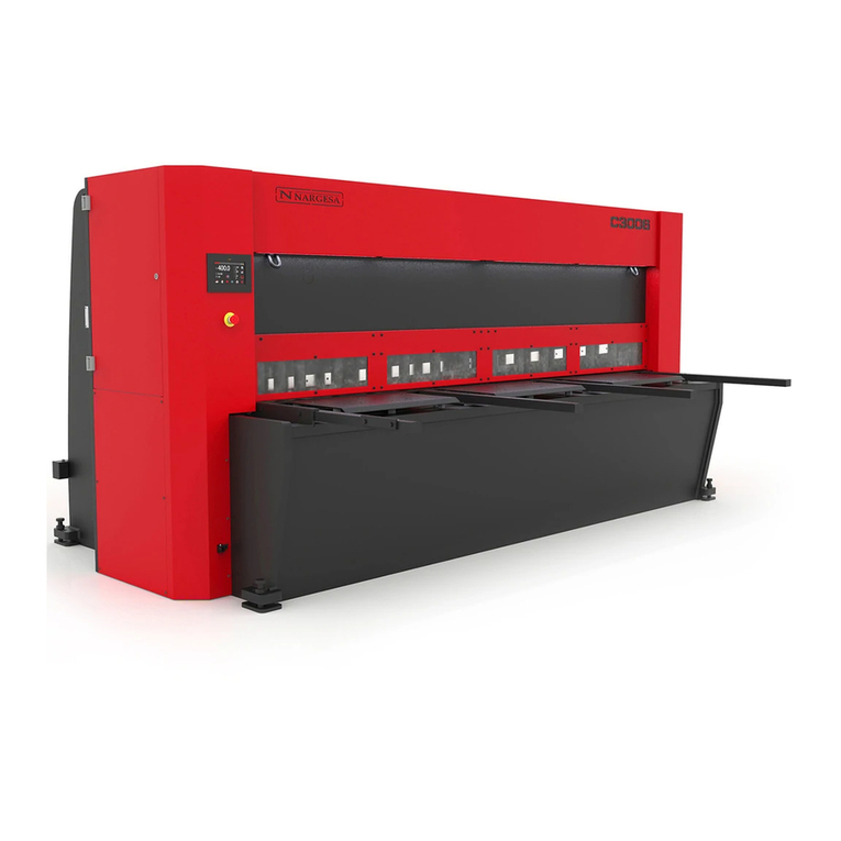
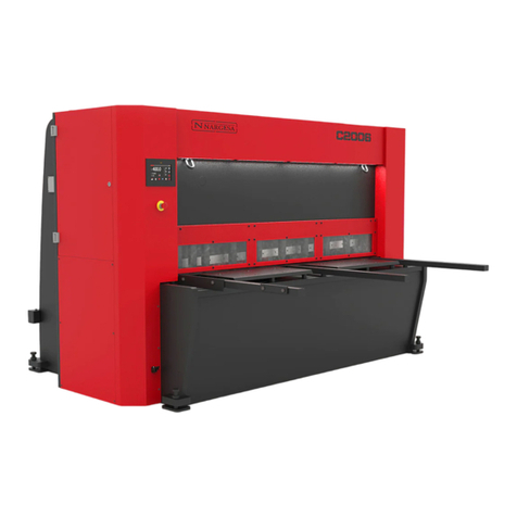
NARGESA C2006 User manual

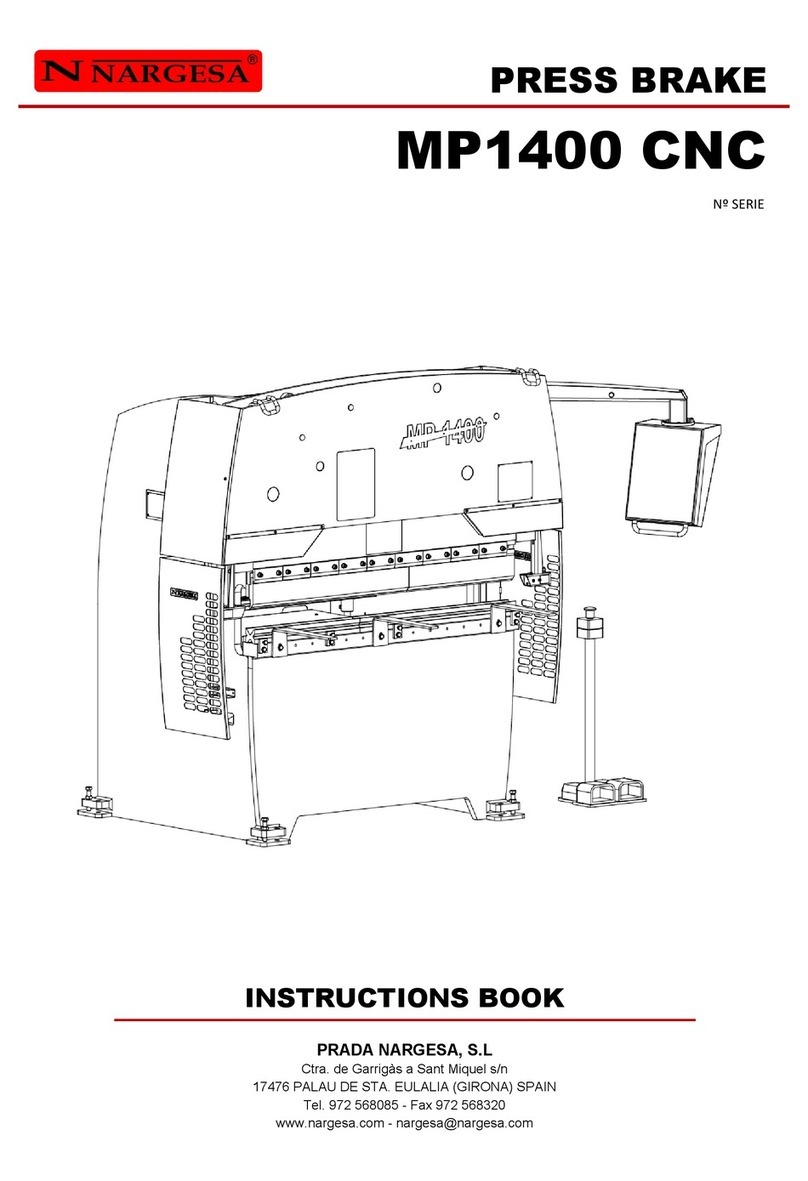
INSTRUCTIONS BOOK
PRADA NARGESA, S.L
Ctra. de Garrigàs a Sant Miquel s/n
17476 PALAU DE STA. EULALIA (GIRONA) SPAIN
Tel. 972 568085 - Fax 972 568320
HYDRAULIC SHEAR
C2006

Thank you for choosing our machines
www.nargesa.com

C2006 HYDRAULIC SHEAR INSTRUCTIONS BOOK 2
INDEX
1. CHARACTERISTICS OF THE MACHINE ...............................................................................
1.1. Identification of the machine .......................................................................................
1.2. General dimensions ....................................................................................................
1.3. Description of the machine ..........................................................................................
1.4. Identification of the machine .......................................................................................
1.5. General features ........................................................................................................
1.6. Description of safety devices ......................................................................................
2. TRANSPORTATION AND STORAGE ....................................................................................
2.1. Transportation .............................................................................................................
2.2. Storage conditions ……………….................................................................................
3. MANINTENANCE ....................................................................................................................
3.1. General Maintenance ..................................................................................................
4. INSTALLMENT AND START UP ............................................................................................
4.1. Location of the machine ..............................................................................................
4.2. Dimensions and working site …...................................................................................
4.3. Admissible outer conditions ........................................................................................
4.4. Connection to power supply ………….........................................................................
5. HANDLING BOOK ...................................................................................................................
5.1. Introduction .................................................................................................................
5.2. Control panel ...............................................................................................................
5.3. Feeding of the guillotine ..............................................................................................
5.4. Activation of the machine ............................................................................................
5.5. Surfing through the top memories ...............................................................................
5.6. Positioning the top .......................................................................................................
5.6.1. Introducing the desired figure ........................................................................
5.6.2. Cancelling the introduction of a figure ............................................................
5.6.3. Considerations to bear in mind ......................................................................
5.7. Operation mode ..........................................................................................................
5.7.1. Manual mode .................................................................................................
5.7.2. Automatic mode .............................................................................................
5.8. Deletion of the cutting meter .......................................................................................
5.9. Correct the top ............................................................................................................
5.10. Menus of the block ....................................................................................................
5.10.1. Menu to edit blocks ......................................................................................
5.10.2. Selection of the block ...................................................................................
5.10.3. Definition of the performance mode .............................................................
5.10.4. Adding cells ..................................................................................................
5.10.5. Eliminating cells ...........................................................................................
5.10.6. Edition of cells ..............................................................................................
5.10.7. Deletion of the cutting meter ........................................................................
4
4
4
4
5
6
7
8
8
8
9
9
10
10
10
10
11
12
12
12
13
13
14
15
15
17
18
18
19
20
21
22
23
24
24
25
26
27
27
29
C2006 HYDRAULIC SHEAR INSTRUCTIONS BOOK 3
5.11. Menu to operate blocks .............................................................................................
5.11.1. Block selection .............................................................................................
5.11.2. Operating with one block .............................................................................
6. ADJUSTMENT OF THE BLADES ...........................................................................................
7. STANDBY OF THE MACHINE ................................................................................................
8. UNUSUAL PERFORMANCE SITUATIONS ............................................................................
9. WARNINGS .............................................................................................................................
10. ACCESORIES ........................................................................................................................
TECHNICAL ANNEXES
30
30
31
32
33
34
35

C2006 HYDRAULIC SHEAR INSTRUCTIONS BOOK 4
1. CHARACTERISTICS OF THE MACHINE
1.1. Identification of the machine
1.2. General dimensions
Picture 1. External dimensions of the machine
1.3. Descripción de la máquina
The guillotine C2006, has been designed specifically for cutting metal sheets.
The manufacturer will not take any responsibility for the damages caused to the machines or the operatives
using it at any other operation different from the ones previously specified.
The C2006 is according to the European regulations and normative for the manufacturing of machinery.
PRADA NARGESA S. L is not liable for any damage that might occur due to misuse or failure by
users to comply with the safety standards.
Trademark Nargesa
Type Hydraulic shear
Model C2006

C2006 HYDRAULIC SHEAR INSTRUCTIONS BOOK 5
1.4. Identification of the machine
Commands control
Rammers
Electric box
Front protection
Screws to level
the machien
Lifting spot
Photocell
Side protections
Stands for the
entrance of the
metal sheet
Power motor

C2006 HYDRAULIC SHEAR INSTRUCTIONS BOOK 6
Picture 2. Nameplate
1.5. General features
Engine power 5,5 KW / 7,5 CV
Three-phased tension 230/400 V
Cutting Capacity: mild steel 6 mm
Cutting capacity: stailess steel 4 mm
Nº of hammers 10 unidades
Cutting length 2030 mm
Neck 190 mm
Gauge displacement 700 mm
Strokes per minute 10 strokes
Position accuracy and repeatibility +/- 0,1 mm
Dimensions 2671x2364x1762 mm
Weight 4850 Kg

C2006 HYDRAULIC SHEAR INSTRUCTIONS BOOK 7
Protection covers must not be removed to do the maintenance works. This job must be carried out by
highly qualified technicians. PRADA NARGESA will not accept any responsibility for the damages cau-
sed by not bearing in mind to what has been previously exposed on this book.
1.6. Description of safety devices
The fixed safety devices the guillotine C2006 has are lateral to avoid any handling, the front protection
avoids from acceding to the rammers side, Protections in the back side of the machine covering the belts
and pulley of the back top, the outet ramp for the material and the upper protection cover of the piston mo-
veable part.
Picture 3. Safety devices
ResBack protection
of the top belts.
Upper safety device for the hydraulic
piston protection.
Outlet rampfor
the cut material.
Front protection to save access
to the cutting blade.
Protection side neck.

C2006 HYDRAULIC SHEAR INSTRUCTIONS BOOK 8
2. TRANSPORTATION AND STORAGE
2.1. Transportation
The lifting of the machine will be carried out by a crane, using the clamping points indicated for that. The
machine will be never lifted by any other side but the indicated one.
Picture 4. Transportation of the machine
2.2. Storage conditions
The machine will not be stored in a place that hasn’t got the following requirements:
* Humidity between 30% and 95% without water condensation.
* Temperature from -25 to 55ºC or 75ºC for a length of time not exceeding 24h (these must be considered
storage conditions)
* It is advisable not to pile up machines or heavy objects on top of it

C2006 HYDRAULIC SHEAR INSTRUCTIONS BOOK 9
WARNING: Stop the machine to make the maintenance.
3. MAINTENACNE
3.1. General maintenance
- The oil container level must be checked every 1000 hours of work.
The peephole to the oil level is located in the upper part of the container. In case there is a lack of oil, just
fill it up to the peephole mark.
- Replace the hydraulic oil container every 4000 hours of work.
- Oil: CEPSA HYDRAULIC HM 68
Once the oil has been changed, it is necessary to start up the machine and activate the pedal in
intermittence by increasing the pressure time gradually until the circuit is full.
- Grease up the bolts periodically according to the level of use.
- If it is a steady and daily use, they must be greased avery month.
- Lubricate the top spindles weekly with grease or oil.
- Lubricate all guides greasers every month.
Drain plug
Oil dipstick
Fill plug

C2006 HYDRAULIC SHEAR INSTRUCTIONS BOOK 10
4. INSTALLMENT AND START UP
4.1. Location of the machine
The machine will be placed properly so that it doesn’t have to be moved, in case this was not possible then
it is necessary to follow the rules described in the Transport section. It muts be placed on a flat and levelled
surface to avoid vibrations and any sort of movement while it’s performing. It is possible to level the
machine by using the screws at the bottom of the machine, at each corner.
Picture 5. Anchor points of the machine
4.2. Dimensions and working site
The dimensions of the machine are to be considered when the machine is put down, as well as the
operative working zone and the possible different sizes of the part to be worked.
The machine will be only used by one operative, who will be located at the front side of the machine and
never in a lateral of it since he has to keep control over the whole set of the machine, moreover the main
prtection devices are designed for th efrontal use of it.
Picture 6. Working site
4.3. Admisible outer conditions
It is advisable to work under the following atmospheric conditions:
- Room temperature between +5 °C and +40 ºC without exceeding an average temperature of +35 °C
within 24 hrs
- Humidity between 30% and 90% without water condensation

C2006 HYDRAULIC SHEAR INSTRUCTIONS BOOK 11
4.4 Connection to power supply
The guillotine C2006 is equipped with two three-phased enngines 230 / 400 V: one of them is for the top
(0,37KW),which must be always connected triangularly and another one (5,5 kW) connected star like to be
connected to a 400v + neutral supply. It must connected to an only supply in the indicated source. If the
line tension is not the one indicated then a change of the engine bobbins will be carried out. As shown in
the pictures below:
Picture 7. Change of engine connections
Star figure
(Default)
For voltage 400V
Triangle figure
For voltage 230V
IMPORTANT
This machine must be connected to a power supply with ground wire.

C2006 HYDRAULIC SHEAR INSTRUCTIONS BOOK 12
5. HANDLING BOOK
5.1. Introduction
This manual is designed for the user of the Guillotine C2006, since it has got important information about
the use of it and the peculiar features of the machine. Therefore it is advisable to follow step by step the
points detailed in this book so a good understanding of its performance could be achieved.
5.2. Control panel
Control screen
Screen to indicate the
cutting size
Number keys
Tension
pilot
Key to block the
machine
To cancel one operation
Enter key to validate the insertion
of sizes
To create the cutting memory or
adjust the blades.
Navigation keys
Keys to edit or remove memories.
Select the going down of the blade
manually
Select the going down of the blade
automaticaly
Go key
Stop key
Delete the orders
In case the top size has to be
corrected, do it by using thie key
with the code: 44223311.

C2006 HYDRAULIC SHEAR INSTRUCTIONS BOOK 13
5.3. Feeding of the guillotine
In order to power on the machine, it is enough jus by set the Go switch in the position o Connected. Then it
will show up al abel on screen as the one below:
Picture 8. Message of activation of the machine
The 7 fragments displays are checked automatically showing a sequence of numbers in regression. Once
this routine revision has been carried out all 7 fragment displays will turn off and will deactivate LCD display
light at the same time, however the same label of Picture 8 will seen .
Right now the machine is in a StandBy mode, it happens when it is activated but in rest position awaiting
any command the user orders.
5.4. Activation of the machine
With the machine already started and in StandBy, it could be activated to work with the steps detailed
below.
Press the key ON to proceed properly. Once you do it you will see a label like the one below and just in
case you finish giving power to the machine as it was described in the section below you will see in the
LCD display an initialization label as the one below
Picture 9. C2006 initialization label
At the same time it will be seen intermitently in the 7-fragments displays the total length of the top while this
is moved at a moderate speed, getting apart from the shears blade in order to be located in the highest
working figure.en la cota Once this top is located in the indicated positions, then the intermitence of the 7-
fragments displays will disappear and these ones will show the value of the top route length.
Likewise, there will be a label in the screen showing the following message which will show the in the
memory of the current top the cutting meter associated to this memory and the position of the top
corresponding to the visualized memory.
NARGESA
C2006
NARGESA
C2006

C2006 HYDRAULIC SHEAR INSTRUCTIONS BOOK 14
Picture 10. Information of the top memory 0
Apart from the information indicated in the previous picture in the upper picture of the LCD display it could
be seen the performance way of the shears, intermitently intercalated with the memory of the current top.
Such a mode allows to make cutting operations with the shears in both, the automatic mode and the
manual mode. So, depending on the performance mode currently selected, it will be seen on the screen a
label of Picture 11 or that of Picture 12, intercalated with the one on Picture 10
Picture 11. Information of the Shears in manual mode.
Picture 12. Information of the Shears in automatic mode.
In case the machine hasn’t been completely fed then it will show directly in the LCD display all information
shown in Picture 10, since in this case it is not necessary that the top goes back to the starting point again
on default. Likewise it will be possible to see the current top position of the machine on the 7-fragments
display.
5.5. Surfing throught the top memories
There are 10 preset memories of the top, all of them with the counter to 0 and the position of the top
gradually increased regularly in gaps of 10mm.
To go through the different memories, it is necessary to press the Navigation keys, silkscreen printed with:
To the pressure of each of these keys there will appear on screen the information according to the current
memory of the top.
M00 CONT:0000
TOP = 100.0 mm
MANUAL
TOP = 100.0 mm
AUTOMATIC
TOP = 100.0 mm

C2006 HYDRAULIC SHEAR INSTRUCTIONS BOOK 15
To find the desired memory faster, keep the Navigations keys preddes for more than 1.5 sec. Keeping the
key pressed it will pass to the next memory every 0.25 sec.
An example of a top memory could be the one below:
Picture 13. Information of the memory of the top 6.
5.6. Positioning the top
Press the Return key at the sight of Picture 13 for the top to be located in the indicated figure every (70.0
mm)
Once this has been accried out the top will beging it positioning until it reaches the specified figure. We can
see the position of it in the 7-fragments display as it is moving. Like this we get to know in real time the
location of the top in our shears.
Therefore we can select the desired memory of the top amog the 16 possible ones and once it is displayed
on screen, press the return to confirm the top at which it must be set in the figure shown on the screen.
5.6.1. Introducing the desired figure
Despite the 10 preset memories of the top, it is quite probable to require intercalated which are not
reflected on these memories.
In order to enter the desired figure just insert the new value for the top positioning by using the number
keyboard. Once this value has been inserted, confirm it by pressing the return key, placing the top in the
new inserted position.
Let’s see an example of the steps to follow, with the new inserted figure of 443.2 mm:
Picture 14. Information of thetop of the memory 0
At pressing the first number ( 5 in our sample), the message on the screen changes into this other one:
Picture 15. Inserting a new figure
M6 CONT: 0000
TOP = 70.0 mm
M00 CONT: 0000
TOP = 10.0 mm
M00 CONT: 0000
“”””””””” 5.0 mm

C2006 HYDRAULIC SHEAR INSTRUCTIONS BOOK 16
Now we insert the second number followed by the third one, shown in this screen:
Picture 16. Inserting the new figure.
Picture 17. Inserting the new figure.
Next we press the key according to the Decimal Point, what enables us to see on the screen what follows:
Picture 18. Inserting a new figure
Finally, we insert the final number (2, in this example),getting a new figure as it can be seen in Picture 19:
Picture 19. Inserting a new figure
Once these simple steps are carried out, we press the Return Key to confirm the value that has been
inserted. Then unless the new inserted figures is not higher than the total length of the top, it could be seen
on the LCD displays the information reflected in the following picture:
Picture 20. Inserting a new figure
M00 CONT: 0000
“””””””””””” 43 mm
M00 CONT: 0000
“””””””””””” 443 mm
M00 CONT: 0000
“””””””””””” 443 mm
M00 CONT: 0000
“””””””””” 443.2 mm
POSITIONING
TOP = 443.2 mm

C2006 HYDRAULIC SHEAR INSTRUCTIONS BOOK 17
Right now the top will activate moving towards the specified position, what can be seen by taking a look at
the 7 fragments display. When the top reaches the desired figure it stops, and it is reflected in the seven
fragments displays.
Now that the top is in the new position, the information shown in the display is the one below:
Picture 21. Information of the memory of the top 0
Picture 22. Information of the guillotine in manual mode.
5.6.2. Cancelling the introduction of a figure
In case we have gone wrong while inserting thr new figure we can cancel the operation pressing the ESC
key
Picture 23. Inserting the new figure.
When we do that the memory of the current top shows up on screen again, with the value thet it had before
the modification we were going to make.
Picture 24. Information of the memory of the top 0
M00 CONT: 0000
TOP = 443.2 mm
MANUAL
TOP = 443.2 mm
MANUAL
TOP = 443.2 mm
M00 CONT: 0000
TOP = 10.0 mm

C2006 HYDRAULIC SHEAR INSTRUCTIONS BOOK 18
5.6.3. Considerations to bear in mind
It is impossible to insert a figure higher than the total effective length of the top. It is like that because it is
not possible to put the top beyond the physical limits that it has itself.
Therefore, if the total effective length of the top is 500.0 mm, we will see the memory of the current topwith
the value it had before, although we can insert on the screen a value higher to this one,such as 550.0 mm,
when we press the Return Key to confirm the new figure, we see the memory of the current top again with
the value that it had before its modification.
Picture 25. Information of the memory of the top 0
Picture 26. Modificating the memory of the top 0
When pressing the key return to confirm and due to the fact that the inserted figure is higher to the total
(500.0 mm), the top will not move and in the screen we will see the label on Picture 25 again:
Picture 27. Information of the top memory 0
5.7. Operation mode
As it has been pointed out before, the shears has two modes of performance, in order to make the cutting
operations. These are: Manual mode and Automatic mode.
In the memories of the top, the performance mode of the machine is Manual on default. This performance
mode is the same for each o f the 10 memories the top has and that could be changed if desired. Just
follow the steps detailed below if the performance mde of the shears wants to be changed:
If your intention is to work with the machine in the automatic mode, press the AUTO key. Once this has
been done you will see how the shears blade will go up til the upper rest position.
If on the other hand your intention is to operate in Manual mode, the only thing to do is to press the Manual
key. In this case, unlike the previous one, the blade will not move.
M00 CONT: 0000
TOP = 50.0 mm
M00 CONT: 0000
TOP = 550.0 mm
M00 CONT: 0000
TOP = 50.0 mm

C2006 HYDRAULIC SHEAR INSTRUCTIONS BOOK 19
5.7.1. Manual mode
If your choice is to make the cutting operations with the shears in Manual mode, then proceed by following
the information indicated in the following pictures:
Picture 28. Information of the memory of the top. 1
Picture 29. Information of the shears in manual mode.
Once the cutting sheet is introduced, press the pedal for the blade to go down In the manual mode, the
blade goes down while you keep the pedal pressed down, in such a way that if you loose it, then the blade
changes its movement the other way around and starts going up until it reaches the upper rest position.
Then once we get to know this performance principle, if a sheet need to be cut, the user has to press the
pedal until the blade reaches the lower position of its vertical route. Once it is there and therefore it has cut
the sheet, it won’t go up again until you stop pressing the pedal. If you do it the shears blade will start
moving until it reaches the upper rest position.
You have to know also that if you press the pedal while the blade is going up, the blade will invert its
movement and will go down again.
On the other hand and as a remarkable point, you must be conscious that every time you press the pedal
to make one cutting operation, it will automatically increase the cutting meters associated to the memory of
the top that is performing. This will show in the following picture:
Picture 30. The memory meter of top 1 has been increased
Therefore, if the pedal is pressed several times to make a cutting operation, the couter meter will increase
the same number twice, since te machine will take for granted that you have made all those cuts. This kind
of performance is based in the need to count all the times the pedal has been pressed, because several
times the machine’s rented to other people and the rental price depends on the number of cuts made. So
the operative will make a reasonable use of it, since the more times he presses the pedal to make the
same number of cuts of sheet, the more expensive the rental will be.
M01 CONT: 0000
TOP = 330.0 mm
M00 CONT: 0000
TOP = 330.0 mm
M00 CONT: 0000
TOP = 330.0 mm
Other manuals for C2006
1
Table of contents
Other NARGESA Power Tools manuals

NARGESA
NARGESA MP3003 CNC User manual

NARGESA
NARGESA MP3003 CNC User manual

NARGESA
NARGESA MP1400 CNC User manual

NARGESA
NARGESA MX340G User manual

NARGESA
NARGESA MC400 User manual

NARGESA
NARGESA C3006 User manual

NARGESA
NARGESA C2006 User manual

NARGESA
NARGESA MX340G User manual

NARGESA
NARGESA C3006 User manual
Popular Power Tools manuals by other brands

Universal Tool
Universal Tool UT1520S operating instructions

DeWalt
DeWalt XR DCS331 Original instructions

Parkside
Parkside PSTDA 20-Li A1 Translation of the original instructions

Holzstar
Holzstar KSO 790 instruction manual

Bosch
Bosch GBH18V-45C Operating/safety instructions

Makita
Makita PJ7000 instruction manual