TraffiCalm Wrong Way Alert M75-DETCA-M000 User manual

Use and Operation Guide
PN 029-05096-0000 rev A
Applies to the following assemblies:
M75-DETCA-M000
M75-DET0A-0000
This guide is designed to asssist in the installation of
TraffiCalm’s Wrong Way Alert System:
• System Design
• Theory of Operation
• Installation
• System Configuration
• Validation Testing
• Notification Monitoring
• Maintenance
In addition to this guide, installation manuals and
supplements have been delivered with the product.
These are also available at Trafficalm.com/wwa.
TraffiCalm greatly appreciates your investment in our
solutions, if at any time you require additional assistance
feel free to give us a call at 855-738-2722

2
⟨System Design⟩
Components:
All TraffiCalm™Wrong Way Alert Systems consist of these basic
elements:
• Controller (M75-DETCA-M000 or M75-DET0A-0000)
• Multiple Collaborators
• Radars
• Power Supplies
• LED Sign Enhancement Rings or RRFBs
Additional accessories include
• Expanded-use power supplies (low temp, solar, etc)
• Internally-illuminated signs with LED enhancement rings
• other detection methods (loops, for example)
System Layout
A single Wrong Way Alert Controller works in conjuction with
at least one Collaborator (and up to 12) to create a network that
covers a road section (typically a ramp) in consistent detection,
resulting in timely warning to drivers and, if equipped, reliable
notification to your designated monitoring team.
Detection is accomplished with up to eight (8) radar detector
units. Each radar unit is connected to either the Controller or a
Collaborator.
Radars (and their respective Collaborator) are configured into
one of 4 detection “zones”
1. Flasher Activation Zone
2. Pre-Alert Zone
3. Alert Zone (always shared with the Controller)
4. Confirmation Zone
As noted above, the Controller is ALWAYS in the Alert Zone

3
What it all looks like
⟨System Design⟩
Radar
Collaborator
Controller (with
Camera)
Enhanced
Wrong Way Sign
Reason we need
wrong way
mitigation
4
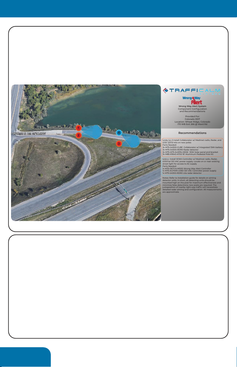
In anticipation of your project we supplied design guides (example
shown below) that itemized the hardware used per specific road
section (typically a ramp) and per post. This guide is critical to the
success of the installation and should be available for reference during
the planning and installation phases. After the installation, this guide
can be referenced during maintenance and, if needed, repair.
Recommendations
Units 1,2, 3 Install Collaborator w/ Meshnet radio, Radar, and
solar panel kits on new poles
Parts Needed:
3x M75-SA300-CLBE Collaborator w/ integrated 13Ah battery
3x M75-SA300-RDR0 Radar detector
3x M75-M75-SLRPN-030W 30W Solar panel and bracket
3x M85-R1640-AT00 16’ Aluminum Pedestal Pole Kit
Unit 4 Install WWA Controller w/ Meshnet radio, Radar,
external 120 VAC power supply. Locate on or near existing
street light for access to AC supply
Parts Needed:
1x M75-DETCA-M000 Wrong Way Alert Controller
1x M75-ACPWR-U060 120 VAC Controller power supply
1x M75-SA300-RDR0 Lite radar detector
Notes: Refer to installation guide for details on aiming
detector units. In short, all detecting units should be
mounted high on the post for maximum effectiveness and
minimize false detections; new posts are required. The
juxtaposition of nearby right-way trafc will necessitate
detailed radar aiming and conguration. All measurements
are approximate.
Wrong Way Alert System
Component Conguration
and Recommendations
Provided For:
Colorado DOT
Location: Wheat Ridge, Colorado
I70 WB Exit 266 @ Ward Rd
3
1
2
4
example of design guide/pictorial
The design guide portrays the functionality of our system and
how the specific components will need to be placed in order to
perform well for the given ramp.
The design guide was created remotely, with information at
hand. Locally exclusive information may dictate change orders to
the design of the system, these should be noted and updated on
the design guide.
Note that the visualized radar aiming is approximate, further in
this guide we will cover radar aiming theory.
⟨System Design⟩
5
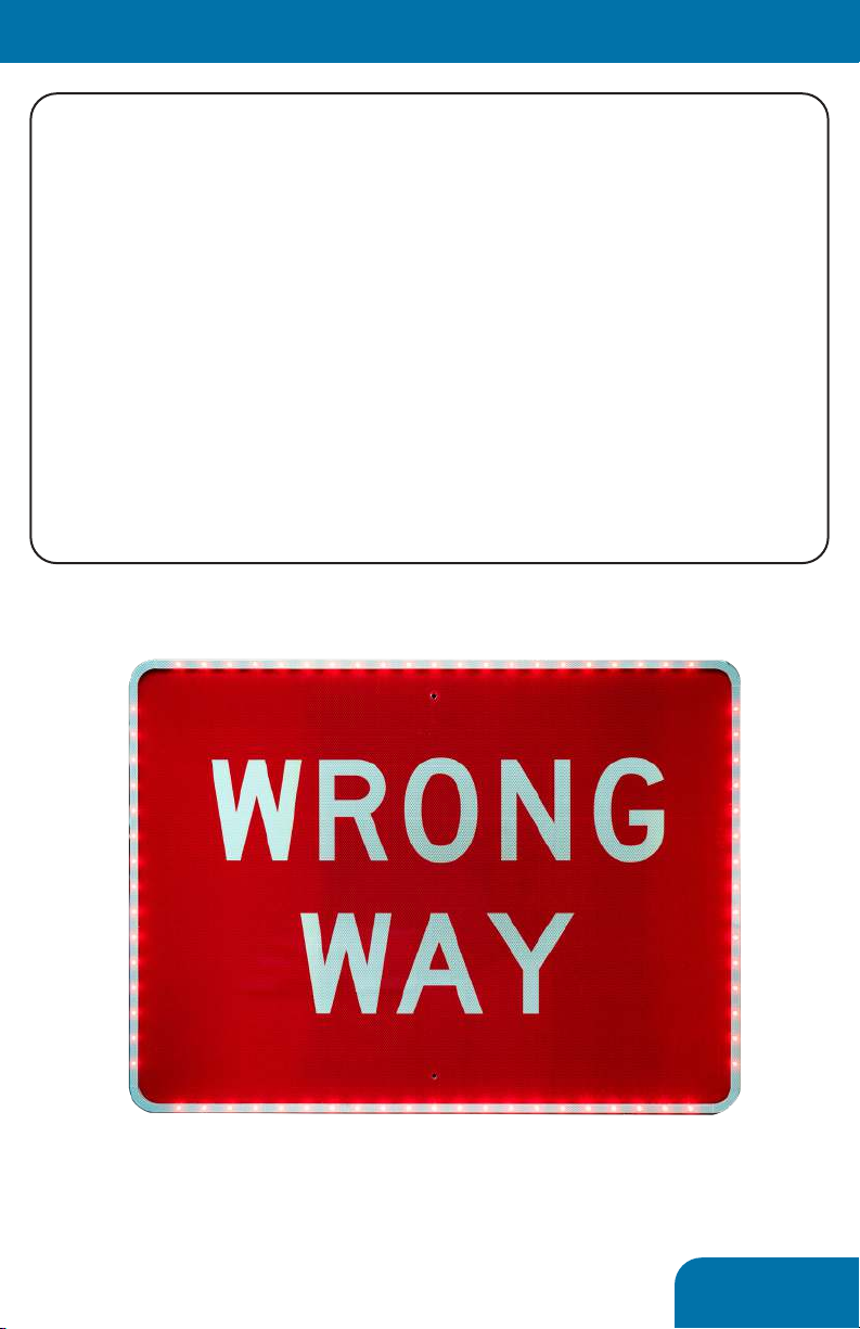
LED Sign Enhancements:
The supplied sign enhancements are made to install to any
Wrong Way or Do Not Enter sign manufactured to MUTCD
requirements. They can be highlighted in either red or white
LEDs and are designed to provide ample warning to any wrong
way driver in almost any condition, day or night.
The LED enhancements can be connected to any Controller or
Collaborator in the system. Up to 8 can be collocated with the
radars; an additional 4 sign enhancements can be added to
Collaborators in a “Flasher Only” grouping.
LED flashing will only occur upon succesful detection of a wrong
way vehicle
⟨System Design⟩
LED intensity is hard to photograph

6
Before installing the system...
The three main goals of any wrong way mitigation system:
1. Detect Wrong Way Drivers (WWDs) in any condition
2. Prompt WWDs to self correct and safely turn around
3. Notify monitoring facilities if a WWD does not self correct
(only available on the M75-DETCA-M000 model)
Trafficalm has developed a proven system that can accomplish
all three with minimal hardware and stellar performance
Performance must be measured by two factors:
1. Ability to warn any wrong way driver
2. Ability to send undeniable evidence of a WWD’s activity to a
system or person that can act upon the reported activity
Wrong Way Alert has been developed to make installation not
only easy, but nearly foolproof. However, it is still important to
understand a few core concepts...
⟨Theory of Operation⟩
RADARS
We use many “small” radar detectors to create up to 4 zones
of detection. While each zone can consist of a single radar, it is
highly recommended that two make up the zone.
The more radars and zones that are incorporated the more
accurate a system can be considered. It is entirely viable to
create a system with just one radar, but the chance for false
detections increase dramatically. Adding a second radar will
halve the occurance of false calls, a third will halve it again.
Typically, a complete system that can deliver at least a 99.5%
accuracy rate consists of 4 radars in two zones.
Somewhat counter-intuitively, our radars are aimed at a very
sharp angle down at the roadway, and a very sharp angle inward
toward the center of traffic. We will cover more of this concept in
the installation section.

7
Collaboration
The Controller wirelessly receives all the detection data from the
radars. This information is validated by a collaboration algorithm
that determines whether a notification should be sent or not.
The stages as a wrong way driver passes through the zones is as
follows:
1. First zone (flasher only) breach results in all signs flashing
2. Second zone (pre-alert or alert) breach results in notification
being sent unless a third zone is incorporated.
3. Third zone breach (alert) sends notification unless a fourth
zone is incorparated.
4. Fourth zone (confirmation) breach sends notification.
How does it work? The system’s algorithm considers the
vehicle speed and distance travelled (determined by series of
detections). A real vehicle will have a predictable signature of
detection which can be relied upon for sending notification.
⟨Theory of Operation⟩
WRONG
WAY
WRONG
WAY
WRONG
WAY
WRONG
WAY
example of typical 2 zone, 4 radar setup

8
Introduction
Typically most systems are installed at this point. However, it is
still beneficial to understand how the individual components
are deployed in the field, especially where maintenance will be
required.
In this section we will detail each component and notes on its
installation.
Typical installation procedure...
1. Affix LED enhancment ring to sign face (if needed)
2. Install Controller or Collaborator
3. Install supporting power supply (solar panel, battery box, AC
inverter, etc.)
4. Install Radar high on post
5. Install sign and LED ehnacement ring to post
6. Make all connections between devices
7. Power on Collaborators
8. Power On Controller
9. Configure System
⟨Installation⟩
Mounting Methods
Various methods can be used to mount our components. An
installation kit is supplied which contains bolts for mounting to square
posts and banding brackets for mounting to round posts or unusual
infrastructure. No banding or banding tool is supplied. Where banding
is used, it is recommended that 3/4” banding be double wrapped to
ensure maximum stability in windy and icy conditions.
Some of our solar panel brackets require large u-bolts (not supplied)
not readily available. It is highly recommended this be planned for and
purchased accordingly. They are the best possible way to mount our
solar panels to ensure years of trouble free service.
ALWAYS ensure the antennas have clear line of site
to the Controller!(!!!)
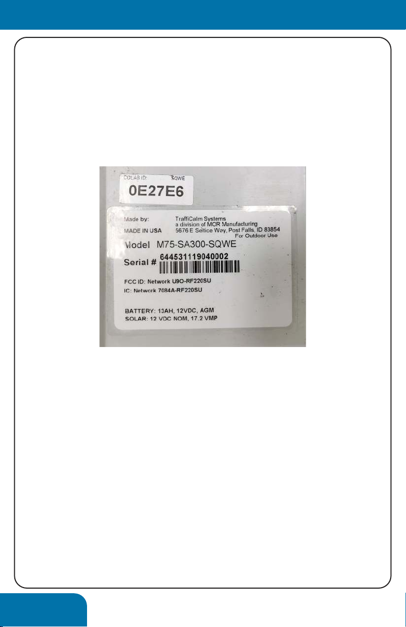
NOTE: It is prudent to take note of each Collaborator’s ID
number and location before installing on the post!
9
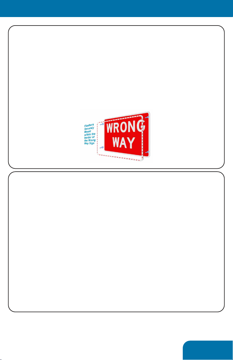
LED Enhancement Rings
The supplied LED enhancment rings (wrong way or do not
enter) are designed as a cohesive ring that affixes to the face of
the respective sign. A single wire exits the top left or right of the
ring; no hardware or cabling are visible on the back of the sign.
To attach the ring, peel and stick the addhesive backing to the
sign. It is highly recommended that the sign be cleaned with the
supplied alcohol wipes before adhering the ring.
⟨Installation⟩
⟨Installation⟩
Controller
Critical-The controller has two antennas that must be installed
before power is applied!
If utilized, the radar must be attached before power is applied
The controller should be located on the post or infrastructure
so that all supporting components can be connected with the
supplied lengths of cable and conduit.
It is also important to consider camera aiming. See the next
segment for more info
The controller features two mounting tabs, top and bottom, that
are spaced on 1” centers for mounting directly to square posts.
Alternatively, banding brackets can be used in the same location

10
Camera Aiming (applies to M75-DETCA-M000 only)
The camera provides critical information about a wrong way
event. As such, proper aiming is important to provide as much
information as possible. From our experience, the most alarming
video evidence is when a wrong way driver’s headlights are
captured; so we recommend that the camera be aimed into
wrong-way traffic. An added benefit to this aiming is the
potential to see the source of the wrong way driver. Traffic
engineers have used this data to advise and justify physical
changes to the road to prevent future incidences.
The camera is manually aimed, zoomed, and focused, but
can be hard to visualize without seeing the result. During the
configuration phase, we will explore how to locally stream the
camera’s footage.
⟨Installation⟩
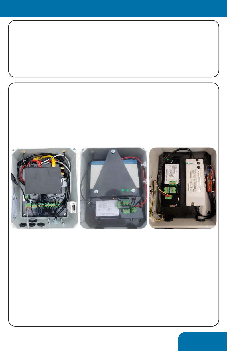
Power Supplies
It is highly advised that AC power be utilized where possible to
ensure maximum reliability. However, where AC power is not
accesible, other options are available.

11
Power Supplies, cont’d
The Controller can operate on any 12V source supplying about 6
amps of power. We spec (and supply) the following options:
• Outdoor rated AC inverter
• Battery charger kit that can operate off timed street lamps
• Large solar kits to provide completely off-grid power
Many systems use a combination of power- AC at the Controller
and solar power at the Collaborators
Unlike the Controller, the Collaborators are configured for their
specific power type and feature built-in components to support
the supplied power.
AC Collaborators receive AC power terminated directly inside the
unit.
Solar powered units feature a 13Ah extreme temperature battery
built into the unit. A 20W, 30W, or 60W panel can be supplied to
charge the battery. All charging circuitry is integrated into the
unit. A single wire runs from the solar panel into the box.
Where solar power is utilized, ensure that the solar panels are
south-facing and angled at 45 (off of level). A calculation typical
to solar installation can be utilized to measure an exact angle
specific to your latitude.
⟨Installation⟩
example of solar setup, from the ground
12
Radars
Much of the system’s success or failure relies on the radar’s
aiming and configuration. Some of this will be a matter of trial
and error on every site, but some guiding principals will help...
The radar can detect a wrong way vehicle driving toward it or
away from itself. The configuration will designate the desired
function.
The radar should be mounted as high as possible on the post or
infrastructure. Height maximizes the unit’s ability to be aimed
correctly and to exclude periphery activity not constituting
wrong way driving.
Nothing (Controller, solar panel, signage, etc.) should obstruct
the immediate face of the radar.
As much as possible the radar’s view should be minimally
obstructed by nearby signage, buildings, or foliage. Such objects
can cause dead spots, reflections,
or small motions that will
obfuscate functionality.
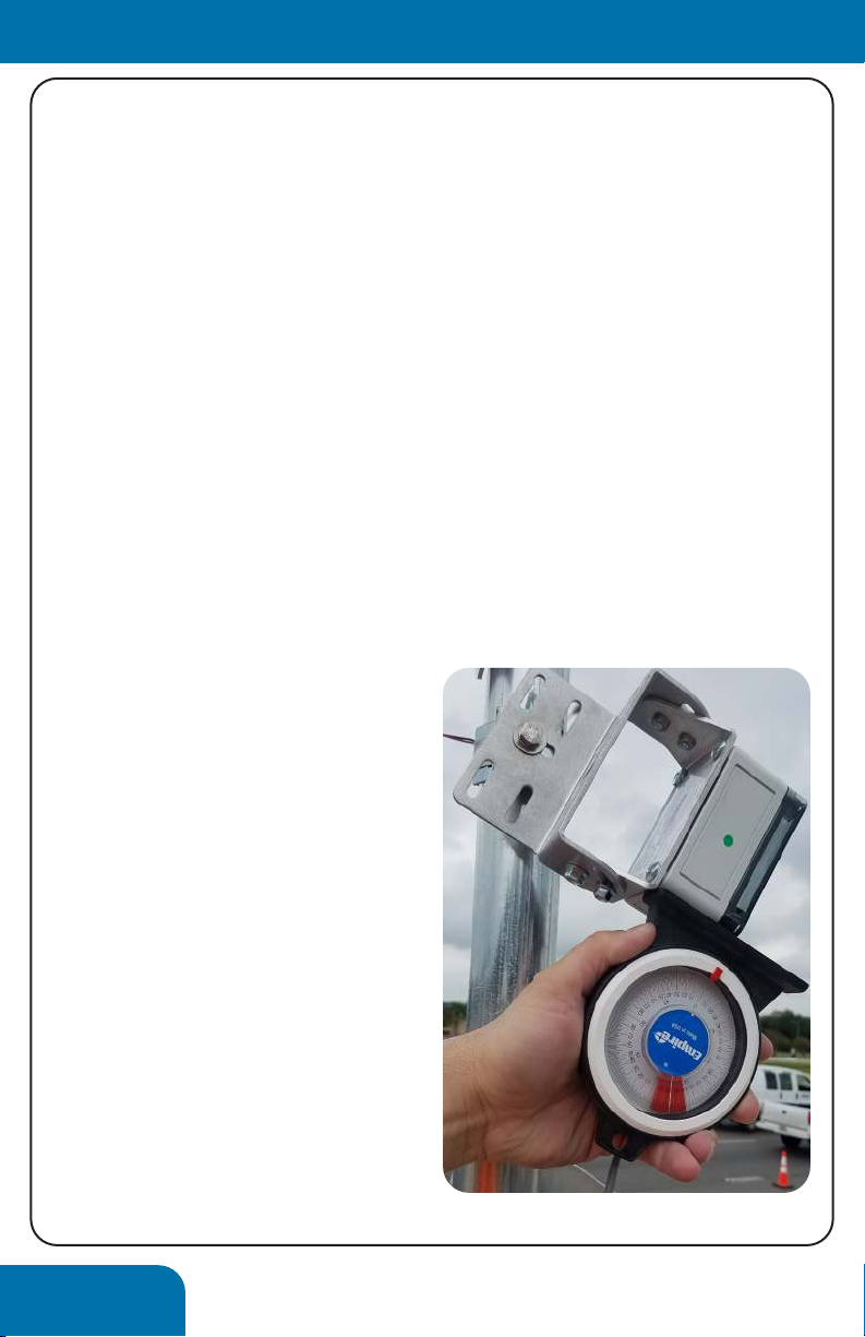
The radar mounting bracket
accomodates a great angular
adjustment of the radar. As
shown at right, it can be rotated
both up and down, as well as left
and right to achieve an accute
(45, typically) aiming at the
roadway.
You want the radar to spotlight
a small section of roadway about
60’ (183m) in front of the post.
Higher aiming (broadcast) will
produce false detections that
are difficult to exclude with
configuration settings.
⟨Installation⟩
13
Signage
With the LED enhancement applied the sign will mount as any
other road sign. It is important that the cable exit the ring at the
top left or right corner.
Hardware to mount the signs is not supplied, but readily
available at any hardware store or sign supply shop.
⟨Installation⟩
Making Connections
Within the Controller and Collaborator are labeled headers for
each connection. No other connections within the box will need
to be made, as these are all connected and tested at the time of
shipment. If applicable, the battery terminal block may need to
be connected.
Our components utilize quick capture connections. To terminate
a wire, strip the wire back 10mm, dpress the orange tab on the
terminal, insert the wire, and release the tab. The whole green
connector block may be removed to ease connections.
All the Collaborators in a group can be powered on at any
time. However, due to a 2 hour security time out, it is advised
that the Controller be powered on in the final stage of
installation.
Controller Solar Collaborator AC Collaborator

14
Overview
Configuration is compatible with any wi-fi enabled device. This
includes smartphones, tablets, and PCs.
2-5 minutes after being powered on, the Controller will activate
a wi-fi network (identified as a unique id containing WWA”)
available for connection. Connect to this network as any other,
through your device’s wi-fi settings. You will need to use the
following password:
Tr@ffiCalm (case sensitive)
The device will warn you that no internet connection is available;
this is expected and should be excused. Open the web browser
of choice (Explorer, Chrome, Safari, and Edge have been tested
functional) and navigate to:
Setup.trafficalm.com
You will be prompted for the following password:
Tr@ffiCalm
The setup wizard will take you step by step through the system
configuration and setup.
Configuration will be in the following order:
• Flashing Options
• Alert Zone Setup
• Flasher Activation Zone Setup
• Pre-Alert Zone Setup
• Confirmation Zone Setup
• Flasher Only Setup
• Advanced Options
• Camera Aiming (applies to M75-DETCA-M000 only)
The configuration wizard is fairly self explanatory, but the
following pages are the highlights...
⟨Configuration⟩
15
Setup Wizard
You will set up the Alert zone first as this contains the Controller.
The radar can be set to either approaching or receding, set in
whatever direction a wrong way driver would be detected by the
radar. The default radar sensitivity settings typically suffice. The
radar angle and zone size will need to be adjusted according to
the system’s phys properties.
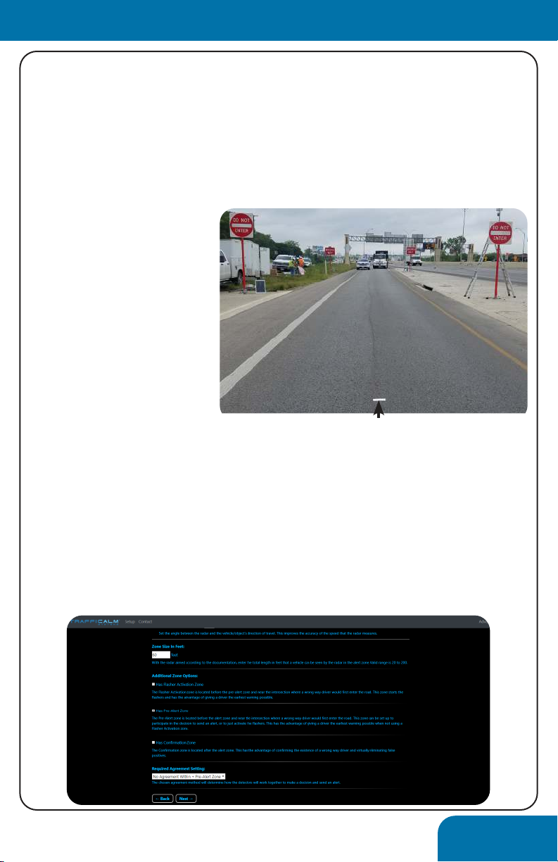
The zone size can be
measured by walking at
the radar and observing
the diagnostic lights on
its face. When the light
turns red, detection
has begun (mark
this location on the
road). When the light
extinguishes, detection
has concluded (again,
mark this location). Measure and enter the distance between the
two marks.
If present, you can add a Collaborator’s ID (ie. 0E23DB) in the
Alert Zone and set it up like the Controller.
The final selection on the Alert Zone page will be what other
zones will be utilized and how they will collaborate. Select
the radio button next to each desired zone and select the
collaboration option from the drop down menu.
⟨Configuration⟩
marker on roadway
16
Setup Wizard
Don’t be alarmed, the next screen will look exactly the same as
the previous; the exception being that it is now titled PRE-ALERT
ZONE SETUP. The settings are similar, but specific to the two
Collaborators you are setting up. An example of the Collaborator
ID is seen below. Every Collaborator has one, and they should be
noted before installation, they can prove difficult to read from
the ground
In the Pre-Alert Zone Setup, the distance of the zone (as
previously explained) must be set. Additionally, the distance
between the Pre-Alert Zone and the Alert Zone must be
designated. Measure the zones center to center to come up with
this number.
Finally, select whether the two radars within the zone require
collaboration. Leaving this box unchecked will create a zone
where a detection on either radar constitutes a collaboration.
Remember, a notification will not be sent off of a single zone
collaboration.
The Flasher Activation and Confirmation Zone Setup pages will
be identical in function. Again, each can be setup with 1 or 2
Collaborators.
⟨Configuration⟩

17
Setup Wizard
The final step in the Setup Wizard is adding “flasher only”
Collaborators. These are devices that do not connect to a radar;
they only serve the purpose of flashing connected signage. This
setup allows for expansion of the system’s warning beyond just
the 4 detections zones.
⟨Configuration⟩
Camera Aiming (applies to M75-DETCA-M000 only)
The camera’s footage can be streamed wirelessly to your PC,
phone, or tablet for aiming purposes.
To access the camera navigate to the following IP address:
192.168.0.50
The camera utility will prompt you for the following username
and password:
User: admin
Password: admin
The live feed from the camera will immediately be visible.
To adjust the camera’s aim, simply loosen the set screws
securing the elbow in place. Take care as these set screws are
small, stainless steel screws and can strip easily. Zooming and
focusing are accomplished with manual adjustments made with
the housing access panel on the bottom of the camera.
Once the desired aim is achieved, replace the desiccant packet,
close the access panel, and check all fittings for tightness.
Advanced Wizard Page
The advanced page has two options and a stream of the
system’s radar detection. A properly setup system will sit idle and
have very few radar detections. If a large number of detections
are presented, it may be required to re-aim the radars or set the
sensitivity settings to less sensitive (more filtering).

18
Validation Testing
After setup has been finalized it is important to test the system.
The first phase of testing should be to observe any sources of
radar “noise” and to adjust the settings and aim to exclude this
noise.
The system can be “reversed” to test on live “right-way” traffic.
Alternatively, and preferably, the road section should be shut
down and live wrong-way testing be performed. We have
developed the following test script for reference...
⟨Testing⟩
Wrong Way Alert Test Script
released: 20190815
Run description Pass? Time to Notify
Lane 1
Lane 2
Lane 3
Lane 1+2
Lane 2+3
Lane 1+3
Notes
This test can be expanded to as many lanes of entry as necessary, we have limited it to three (3)only for
reference. Where alternative methods of detection are utilized (loops, push buttons, etc) the test will
still be effective, though additional hardware settings may be required on the detection hardware. We
have seen this test expanded upon, with different vehicle sizes noted, expanded speeds added, and
additional environmental influences (trains in motion, for example) considered, consider this a starting
point for your own tests.
Notes
Procedure- Where RSUT closure is not permissible; it is feasible to test the system off of active, right way
traffic. The control of speed and traffic volume is inherently impossible in this scenario. System test will
rely on sufficient observation of traffic activating the system from specific lanes of entry. It is advised
that tests occur during hours that traffic is expected to be low; specifically, gaps between passing
vehicles results in improved accuracy and is most indicative of an average wrong way event. With the
assistance of TraffiCalm systems team, these tests can be performed remotely. To perform this test, the
system will be set up in “reverse” of its final configuration. For example, a system consisting of 2 radars
in the Pre-Alert Zone and 2 radars in the Alert Zone, all detecting approaching traffic (wrong way traffic)
will be configured with 2 radars in the Confirmation Zone and 2 radars in the Alert Zone, all set to detect
receding traffic. It is critical that the detection aiming remains identical throughout the test to ensure
proper operation in Wrong Way mode. Once the test is complete, the system can be configured to
wrong way mode by reversing the changes set.
Where ramp closure is not possible

19
⟨Testing⟩
Wrong Way Alert Test Script
released: 20190815
Run description Pass? Time to Notify
10mph, lane 1
25mph, lane1
35mph, lane1
45mph, lane1
10mph, lane 2
25mph, lane2
35mph, lane2
45mph, lane2
10mph, lane 3
25mph, lane3
35mph, lane3
45mph, lane3
25mph, Cross Lanes
Given the variability of ramps and roadways that Wrong Way Alert can cover, it is important to properly
test and verify system functionality. In our experience, a concise test plan results in effective
performance measures that can be relied upon for real world monitoring of dangerous wrong way
events. This script is the result of working with dozens of transportation engineers on real projects and
we feel it is comprehensive, but local knowledge and regulations should be considered when
implementing your own test plan. Note that this procedure is intended to be used after the system has
been configured. All tests should result in a full notification and warning devices being illuminated.
Procedure- Per governing guidelines, the road section under test (RSUT) shall be closed to permit
sufficient and safe passage of a single vehicle traveling the wrong direction at up to 45mph through all
potential lanes of entry; this may include medians and shoulders. The result should be twofold- complete
coverage resulting in notifications being sent from any possible wrong way driving scenario, and no false
detections after the RSUT is opened to live traffic. If a fail occurs, it is (typically) reasonably acceptable to
adjust radar aiming and configuration, and then restart the test.
Notes
Where ramp closure is feasible (recommended)

20
⟨Notification Monitoring⟩
Overview
The net result of a reliable wrong way mitigation system is
trustworthy notification, if equipped. A system that delivers false
notifications too frequently will dilute its own effectiveness.
Additionally, the effectiveness of the notification relies on the
recipient’s ability to view and interpret it. At the guidance of
two state-wide monitoring centers, we developed a network of
notifications that do not rely on constant monitoring. The three
options for notification are:
1. Email on any device and to any email address
2. BlueSentry Web Interface
3. Standalone TMC Notier
The most basic of the three is via Email. Due to its ubiquity, it is
the most commonly adopted method of notifiying. Within 20
seconds of a successfully collaborated detection a full color, 18
second video will be delivered for review. The emial subject line
contains the location and information pertinent to the event and
the attached video serves as fool-proof confirmation of an actual
event. The email also includes a link to our BlueSentry interface
Active all of the time, BlueSentry is a constant monitor of all
connected wrong way systems in your group. Individual user
permissions can be setup so that every operated appears as a
unique visitor (important when the history of detections and
whom cleared them is reviewed). BlueSentry is a straightforward
interface that makes navigating alerts and systems very intuitive.
If immediate, closed-loop monitoring is desired, our standalone
TMC Notifier is a wireless device connected directly to our server
that recieves notifications in real time. Connected to any HDMI
monitor, it can serve as dramatic audible and visual warning in
the hectic environment of a monitoring center.
This manual suits for next models
1
Table of contents
Other TraffiCalm Safety Equipment manuals


Popular Safety Equipment manuals by other brands


Dynatech
Dynatech PQ-4000 UD Instructions for use and maintenance

IKAR
IKAR HWB 2,8 DW Log book and instructions for use

APV
APV EASI-GRIP Installation instruction

TEUFELBERGER
TEUFELBERGER VBM SEIL 14MM Manufacturer's information and instructions for use

Thiele
Thiele TWN 0812 Mounting instructions

Revision
Revision WOLFSPIDER User instructions