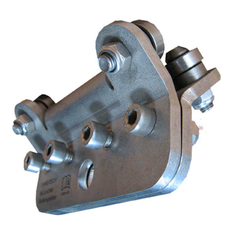
STRUMIN SYSTEMIC EDGE PROTECTION User manual

P a g e | 1
SYSTEMIC EDGE PROTECTION
SAFE WORK AT HEIGHTS

P a g e | 2
ATTENTION !
TECHNICAL DOCUMENTATION
BEFORE EVERY USE OF THE EDGE PROTECTION SYSTEM, THE USER SHALL READ THIS TECHNICAL
DOCUMENTATION AND ALWAYS STRICTLY FOLLOW THE RULES DESCRIBED HEREIN. THESE INSTRUCTIONS
WERE PREPARED FOR ALL WORKERS AND PEOPLE THAT WILL WORK ON TRANSPORTING, UNLOADING,
ASSEMBLING, DISASSEMBLING, STORING, CHECKING AND ANY OTHER WORKS CONNECTED TO THE DEVICE.
EVERY USER IS OBLIGED TO READ AND GET FAMILIAR WITH THE SYSTEM’S TECHNICAL DOCUMENTATION!
CONTENTS:
INTRODUCTION
1.0 MANUFACTURING BASIS
2.0
OPERATING MANUAL
2.1
TERMINOLOGY AND DEFINITIONS
2.2
PURPOSE AND SCOPE OF USAGE
2.3
TECHNICAL SPECIFICATION AND THE CONSTRUCTION OF THE SYSTEM
2.3.1
TECHNICAL SPECIFICATION –INTERMEDIATE BARRIER
2.3.2
TECHNICAL SPECIFICATION –TOE BOARD
2.3.3
TECHNICAL SPECIFICATION –MAIN RAILING
2.3.4
TECHNICAL SPECIFICATION –POLES
2.3.5
TECHNICAL SPECIFICATION –FILLING (INTERMEDIATE BARRIER)
2.3.6
TECHNICAL SPECIFICATION –HOLDERS
2.3.7
TECHNICAL SPECIFICATION –ADAPTERS
2.3.8
TECHNICAL SPECIFICATION –UNIVERSAL FLOOR CLAMP
2.3.9
TECHNICAL SPECIFICATION –FORMWORK CONSOLES
2.4
SYSTEM'S ELEMENTS’DIMENSIONS
2.5
USAGE
2.6
ASSEMBLY OF THE EDGE PROTECTION SYSTEM
2.7
DISASSEMBLING AND MOVING THE DEVICE BETWEEN WORKPLACES
2.8
RULES FOR SAFE OPERATION
3.0
SYSTEM'S CHECK
3.1
MAINTENANCE
4.0 DEVICE’S REGISTER
5.0 RATING PLATE
6.0
7.0 DESIGNER’S STATEMENT
EU DECLARATION OF CONFORMITY

P a g e | 3
INTRODUCTION
This technical documentation contains the guidelines concerning the proper use of THE EDGE
PROTECTION SYSTEM. Workers and other people using the system shall always observe the
guidelines contained herein. In case of any events not described in this document, the occupational
safety and health regulations and other regulations, appropriate to the specific situation, shall be
observed.
It is forbidden to modify the system in any other way than described in the Technical
Documentation. The manufacturer is not liable for any modifications in the system in a way
that is not described in the technical documentation.
1. MANUFACTURING BASIS
THE EDGE PROTECTION SYSTEM is aimed at increasing the safety of works performed at heights.
The project of the edge protection system was prepared in accordance with the current laws
and technical standards:
EN-13374 –Temporary edge protection system
+A1_2019-02E
EN 1090 –Technical requirements for the execution of steel and aluminium structures.
PN-EN ISO 3834-2 –Quality requirements for the welding of
metal materials

P a g e | 4
2.0
OPERATING MANUAL
2.1
TERMINOLOGY AND DEFINITIONS
The edge protection system:
A set of elements used to protect workers from a fall and to catch falling materials.
Main railing:
A railing or an element which makes the upper edge / surface of the edge protection
system.
A protection / intermediate barrier:
A protecting barrier (made of a net or a set of other elements) between the main railing and
a working surface.
A toe board:
A standing / vertical element used to stop materials and protect people from falling or
sliding down from the working surface.
A pole:
The main element of the edge protection system to which the main railing and the toe board
are assembled.
A holder:
An element used to assemble the pole to a given working surface.
The height of the edge protection system:
The distance from the highest point of the main railing to the working surface, measured
perpendicularly to the working surface.
A working surface:
The surface on which a worker stands, walks or works.

P a g e | 5
2.2
PURPOSE AND SCOPE OF USAGE
The edge protection system is aimed at securing the outer edges of buildings and used as a
protection measure while performing works on lower levels and to secure communication strings.
The edge protection system is used while performing constructional works for, primarily, protecting
and preventing from the falls of people an objects onto the lower working levels. The protection
system encompasses areas near the floor's edge and other areas that demand protection.
The EN-13374+A1_2019-02E standard defines three security areas between the floor and the
ceiling;
Ca1 (from the floor to min. 1 m above the floor), Ca2 (from 1 m to 2
m above the floor),
Ca3 (from 2 m to the ceiling).
This definition includes in particular the security range of the Ca1 area.
The protection system (for all three classes: Ca1, Ca2 and Ca3) was also designed on the
basis of the requirements concerning the protection from objects carrier by wind (EN-
13374+A1_2019-02E, point 6.3.4).
The system was designed on the basis of the “Class A” requirements, described in the
5.2.1 of the abovementioned standard.
The system is characterised by an easy, universal and quick assembly to the front and the upper part
of a floor, as well as to a wall. Thanks to the lightness and flexibility of the system, it is possible to
adjust it to all building conditions.
The edge protection system is an affordable and quick way to secure working areas where there is
the need to increase the level of safety.
The use of the edge protection system is allowed only on condition that the user adheres to this
Technical Documentation, as well as the proper occupational safety and health regulations.

P a g e | 6
2.3
TECHNICAL CHARACTERISTICS AND CONSTRUCTION OF THE SYSTEM
The edge protection system is a steel construction (or metal-wooden) consisting of three main parts: an
assembly holder, a pole and an intermediate barrier.
The intermediate barrier can be set in three different options, e.g. as horizontal balk, a steel panel net or a
polypropylene net with an edge line.
The system's module consists of a pole with a holder and a proper barrier, according the above
description.
Each module of the system contains also optional holders or adapters for different assemblies, e.g.
upper assembly, side assembly, assembly to stairs etc.
TOE BOARD HOLDER
INTERMEDIATE BARRIER
MAIN RAILING
TOE
BOARD
POLE

P a g e | 7
2.3.1
TECHNICAL SPECIFICATION –INTERMEDIATE BARRIER
The intermediate barrier of the Ca1 protection area is defined by the EN-
13374+A1_2019-02E standard in point 4
(Defined load classes A-static loads, B-static loads and low episodic dynamic loads, C-static loads and high
dynamic loads connected to sliding down of people and objects)
And in point 5.2, see Appendix No. 1.
The intermediate barrier of the edge protection system is also defined by such parameters, as the
“mesh density” in the “containment porosity Cp” and the wind class” Cq.
The elements of the intermediate barrier are periodically checked for its wear and suitability for the
use in a safety system. The check is performed by the manufacturer or an authorized body.
PVC MESH –1 mm, H 1.2 mPOLYPROPYLENE MESH Ø5 – H 1.2 m
BALK 32 mm –15 × 250 cmPANEL MESH Ø5 – 2.5 × 1.2 m

P a g e | 8
2.3.2
TECHNICAL SPECIFICATION –TOE BOARD
A standing / vertical element used to protect materials and people from falling or sliding down
from the working surface.
The toe board shall provide the security for the area at the height of 1 cm from the working
surface (measured perpendicularly to that surface)
Its maximum lift towards the working surface equals 2 cm.
TOE BOARD 15 cm
TOE BOARD 15 cm

P a g e | 9
2.3.3
TECHNICAL SPECIFICATION –MAIN RAILING
A railing or an element which makes the upper edge / surface of the edge protection
system.
The distance between the highest railing point and the working level cannot be smaller than 1000
mm (measured perpendicularly to the working surface).
MAIN RAILING
MAIN RAILING

2.3.4 TECHNICAL SPECIFICATION –POLES
Cat. No.: 5160 CLAMPING POLE KBW
Cat. No.: 5150 BARRICADE POLE
Cat. No.: 5140 SINGLE POLE
Cat. No.: 5120 STANDARD POLE
Cat. No.: 5130 LITE POLE
Cat. No.: 5110 H POLE
P a g e | 10

2.3.4 TECHNICAL SPECIFICATION –POLES
P a g e | 11
H POLE –Cat. No.: 5110 –with the height of 120 cm, it is used to prepare a safety barrier with a mesh
filling and a boarding. It can be used for a few types of holders that can be assembled to different surfaces
in different positions.
The pole is locked in a socket by rotating and placing in a working position towards the floor.
It is used to work with horizontal and vertical holders, 500 and 250 adapters, a holder for a
girder, Larsen, a floor clamp and a rammed holder.
LITE POLE –Cat. No.: 5130 –with the height of 120 cm, it is used to prepare a safety barrier
with a mesh filling and a boarding. It can be used for a few types of holders that can be
assembled to different surfaces in different positions.
It is equipped with a self-locking socket of the net.
The pole is locked in a socket by rotating and placing in a working position towards the floor.
It is used to work with horizontal and vertical holders, 500 and 250 adapters, a holder for a
girder, Larsen, a floor clamp and a rammed holder.
STANDARD POLE –Cat. No.: 5120 –with the height of 120 cm, it is used to prepare a safety barrier
with a mesh filling and a boarding. It can be used for a few types of holders that can be assembled to
different surfaces in different positions.
The pole is locked in a socket by rotating and placing in a working position towards the floor.
It is used to work with horizontal and vertical holders, 500 and 250 adapters, a holder for a
girder, Larsen, a floor clamp and a rammed holder.
SINGLE POLE –Cat. No.: 5140 –with the height of 120 cm, it is used to prepare a safety barrier
with a mesh filling and a boarding. It is intended for the assembly in a concrete surface with the
screws for concrete or assembly anchors.
It allows to quickly, easily and cheaply assemble the protective barrier.
BARRICADE POLE –Cat. No.: 5150 –with the height of 120 cm, it is used to prepare a safety barrier with
a mesh filling and a boarding. It is used at construction sites during renovation works, while performing
roadworks and to secure digging deep trenches. An example of usage is separating the area where works
which may cause the risk of potential accident, i.e. falling from height, dangerous wetland etc., are
performed.
CLAMPING POLE KBW –Cat. No.: 5160 –with the height of 120 cm, it is used to prepare a safety barrier
with a mesh filling and a boarding. The pole can be assembled at the edge of the floor by twisting the
lower clamping jaw. Such type of assembly can also be used in case of girders that are placed below the
floor. Thanks to the height of the pole, which is 180 cm, the users can secure the upper level to the min.
required height of 1 m. The maximum jaw’s offset is 50 cm.
The poles are made of constructional steel and are galvanized.

P a g e | 12
2.3.5
TECHNICAL SPECIFICATION –FILLING (INTERMEDIATE BARRIER)
Cat. No.: 5440 MESHWALL NET
Cat. No.: 5430 BARRICADE NET
Cat. No.: 5410 BALK 250 cm
Cat. No.: 5420 MESH PANEL 250 cm
Cat. No.: 5450 MESH PANEL 130 cm

P a g e | 13
2.3.5
TECHNICAL SPECIFICATION –FILLING (INTERMEDIATE BARRIER)
MESH PANEL 250/130 cm –Cat. No.: 5420/5450 –is made of a welded, galvanised net which
consists of three protective areas:
-
upper “shelf” (width = 12 cm) used as a supinated grip.
-
the vertical filling up to the height of 120 cm over the working surface,
-
full steel toe board (height = 12 cm).
The vertical poles are placed differently within the range of 10–20 cm, the oblique placement of the toe
board allows to stop smaller objects (e.g. hardcore) from accidental falling out of the working area.
EPS BALK 250 cm –Cat. No.: 5410 –the intermediate barrier consists of three levels (2500 × 150
× 32 balk).
It protects from falling through the edge of the working level. It is assembled in the H pole holders,
Standard and Single.
The lower balk is a protection –toe board which catches smaller objects accidentally falling from the
working level.
BARRICADE NET –Cat. No.: 5430 –is a barrier made as a non-flexible PVC net. Its main advantage is low
weight, easy assembly procedure, resistance to the weather conditions and universality.
The system is used at construction sites, during renovation works, roadworks and while digging deeper
trenches. It is a warning barrier, informing people about a dangerous area. The poles of the barrier
are made of constructional and galvanised steel.
MESHWALL NET –Cat. No.: 5440 –is a protective barrier made as a polypropylene net. Its main advantage
is low weight, easy assembly procedure and resistance to the weather conditions.
The MESHWALL barrier consists of poles, e.g. LITE, a net and an edge line which works as a supinated
grip and an element stretching the whole system.
The net is manufactured in accordance with the edge protection systems and fall arrest systems (safety
nets) standards.

P a g e | 14
2.3.6
TECHNICAL SPECIFICATION –HOLDERS
Cat. No.: 5280 TOE BOARD HOLDER
Cat. No.: 5210 VERTICAL HOLDER
Cat. No.: 5220 HORIZONTAL HOLDER
Cat. No.: 5270 PLATFORM HOLDER
Cat. No.: 5250 LARSEN HOLDER
Cat. No.: 5240 GIRDER HOLDER
Cat. No.: 5260
WALL HOLDER
Cat. No.: 5230
RAMMED HOLDER
Cat. No.: 5290
ATTIC HOLDER

P a g e | 15
2.3.6
TECHNICAL SPECIFICATION –HOLDERS
HORIZONTAL HOLDER –Cat. No.: 5220 –is used to assemble poles to a moveable surface. It is adjusted to
be assembled in a vertical position to the ground with screws for concrete or mechanical anchors. The
holder has a socket with a blockade that is used to lock the pole and protect it from accidentally taking
out. The horizontal holder contains the toe board holder used in case of using a net or boarding.
VERTICAL HOLDER –Cat. No.: 5210 –is used to assemble poles to a working surface. It is adjusted to
be assembled in a vertical position to the ground with screws for concrete or mechanical anchors.
The holder has a socket with a blockade that is used to lock the pole and protect it from accidentally
taking out. The holder contains also a toe board holder used in case of a connection to the extending
adapter 500/250. It is also used to block the net of prepare a toe board on the level of the pole or the
extending adapter.
TOE BOARD HOLDER –Cat. No.: 5280 –is used to assemble the balk (toe board) or mesh panels on
holders: horizontal, vertical, on girder, on Larsen, rammed and on attic holders.
GIRDER HOLDER –Cat. No.: 5240 –is used to prepare the protective barrier on formwork. Its main advantage
is the speed and simplicity of assembly, it does not require using power tools, anchors etc. The assembly is
limited only to placing an open clamp on the formwork and clenching it with a hammer by ramming a
wedge into the clamp’s socket. With the use of the 500/250 height adapter, in an easy way the workers
may lift the barrier to the level ensuring safety and compliance with standards. It is used during the
preparation of the concrete floor what leads to lifting the working level (while lowering the height of the
protection that was earlier provided on formwork).
LARSEN HOLDER –Cat. No.: 5250 –is used to prepare a protective barrier sheet piles. Its main advantage
is the simplicity of assembly and disassembly. It is limited to tightening the locking screw. A low
weight and the ease of storing and transport are another advantages of that system's element. The
LARSEN holder has a socket with a blockade that allows the lock the pole and secure it from an
accidental taking out.
PLATFORM HOLDER –Cat. No.: 5270 –is used to create working bridges, e.g. in shafts or any niches
where there is the need to create a temporary bridge. The holder is used with wooden balks of 10 cm
width. The assembly to the wall is performed through the Ø16 diameter slot.
ATTIC HOLDER –Cat. No.: 5290 –is used to assembly the poles to the walls and allows to move the
barrier towards and away from the wall. Thanks to this solution the user may adjust the barrier to given
constructional elements i.e. attic etc. The vertical adjustment scope is 34 cm. The height (active) of the
socket is 30 cm –is it the distance to which the holder can be lowered in relation to the working
surface, so that the barrier will keep the 120 cm height. If there is the need to further lower the
holder, the 250/500 adapters shall be used.

P a g e | 16
WALL HOLDER –Cat. No.: 5260 –is used to prepare a barrier assembled directly to the walls (i.e.
protection of window openings, doors etc.). It can be used with formwork and mesh panels.
RAMMED HOLDER –Cat. No.: 5230 –is used to prepare a protective barrier in any surface which allows
to assemble the anchor to the rammed holder. The surface must provide the stability of the barrier
pole, so that it will not deviate from the vertical position due to the influence of the weather conditions.
The holder has a socket with a blockade used to lock it and secure from an accidental taking out.
2.3.7
TECHNICAL SPECIFICATION –ADAPTERS
Cat. No.: 5320 ADAPTER 500
Cat. No.: 5310 ADAPTER 250
EXTENDING ADAPTERS 250/500 –Cat. No.: 5310/5320 –is used to lift the pole of the protective barrier
in case of an assembly e.g. of the vertical holders (where there is the lowering of the barrier in relation to
the working surface). When there is such need, the height adapter allows to lift the protection by
250/500 mm. The adapter has a lower locking socket which works with the holder and an upper socket
working with the pole's socket. The sockets are locking each other what protects from an accidental
taking out. The extending adapters are also useful while preparing barriers on girder or Larsen holders.
In case of lifting the working surface (e.g. concrete floor) they lift the barrier to the level providing safety
and compliance with standards.
The holders and adapters are made of constructional steel and are galvanised.

P a g e | 17
2.3.8
TECHNICAL SPECIFICATION –UNIVERSAL FLOOR CLAMP
FLOOR CLAMP Cat. No.: 5510 consist of:
1.
A lower arm
2.
An upper arm (moveable)
3.
A head (moveable)
4.
A pressing screw
5.
A pressing nut
The clamp is characterized by two types of arm
spacing: narrow and wide.
Based on the assembly needs, the user can configure the
clamp’s elements. The upper arm shall be rotated to the
normal position and turned upside down (180 degrees).
The moveable head shall be adjusted to the
assembled upper holder.
The head shall be place in a normal or turned by
180 degrees position in order to adjust it to the
moveable arm’s socket (see the figure.)
….. The upper arm shall be rotated to
the normal position and turned upside
down (180 degrees)……..
….. The head shall be place in a
normal or turned by 180
degrees……..
4.
2.
3.
5.
WIDE SPREAD
NARROW
SPREAD
1.

2.3.8
TECHNICAL SPECIFICATION –UNIVERSAL FLOOR CLAMP
| 18
P a g e
….. The clamp is characterized by two
types of arm spacing: narrow and wide…….
The maximum spacing 52 cm The
minimum spacing: 9 cm
UNIVERSAL FLOOR CLAMP –STAIRWAYS CONFIGURATION
….. Thanks to a moveable head it adjusts
to the shape of stairs and the soffit …….
The clamp can be adjusted to the flight of stairs.
Thanks to a moveable head it adjusts to the shape
of stairs and the soffit of each flight of stairs.
The head turns freely around the upper arm's
socket, thanks to what it automatically adjusts to a
given shape.

P a g e | 19
UNIVERSAL FLOOR CLAMP –HORIZONTAL CONFIGURATION
The socket is available in horizontal configuration,
adjusted to ledges etc. The pole is assembled to optional
sockets that are placed in the upper and lower arm.
LOWER ARM’S SOCKET
UPEPR ARM'S SOCKET

P a g e | 20
2.3.9 TECHNICAL SPECIFICATION –FORMWORK CONSOLES
THE FIXED AND MOVEABLE CONSOLES are used in the preparation of security measures on the walls’ edges which are
used to prepare formwork. The are also used as a formwork element (to assemble the formwork balk), so they
are a universal solution used in constructional works and increasing the level of safety of the works performed.
This solution uses the holes in walls made during the preparation of formwork.
The solution helps to save time on assembling the protection (no need to drill holes, anchoring etc.).
THE MOVEABLE CONSOLE is an extension of the fixed console when there was used the possibility to move the
formwork balk from the wall.
Cat. No.: 5610 FIXED CONSOLE
Cat. No.: 5620 MOVEABLE CONSOLE
Table of contents
Other STRUMIN Safety Equipment manuals
Popular Safety Equipment manuals by other brands
Summit Treestands
Summit Treestands Seat-O-The Pants Series instructions
Duct-O-Wire
Duct-O-Wire RPB Series quick start guide
MTM HYDRO
MTM HYDRO 14.0349 user manual

CanaSafe
CanaSafe TiGer manual
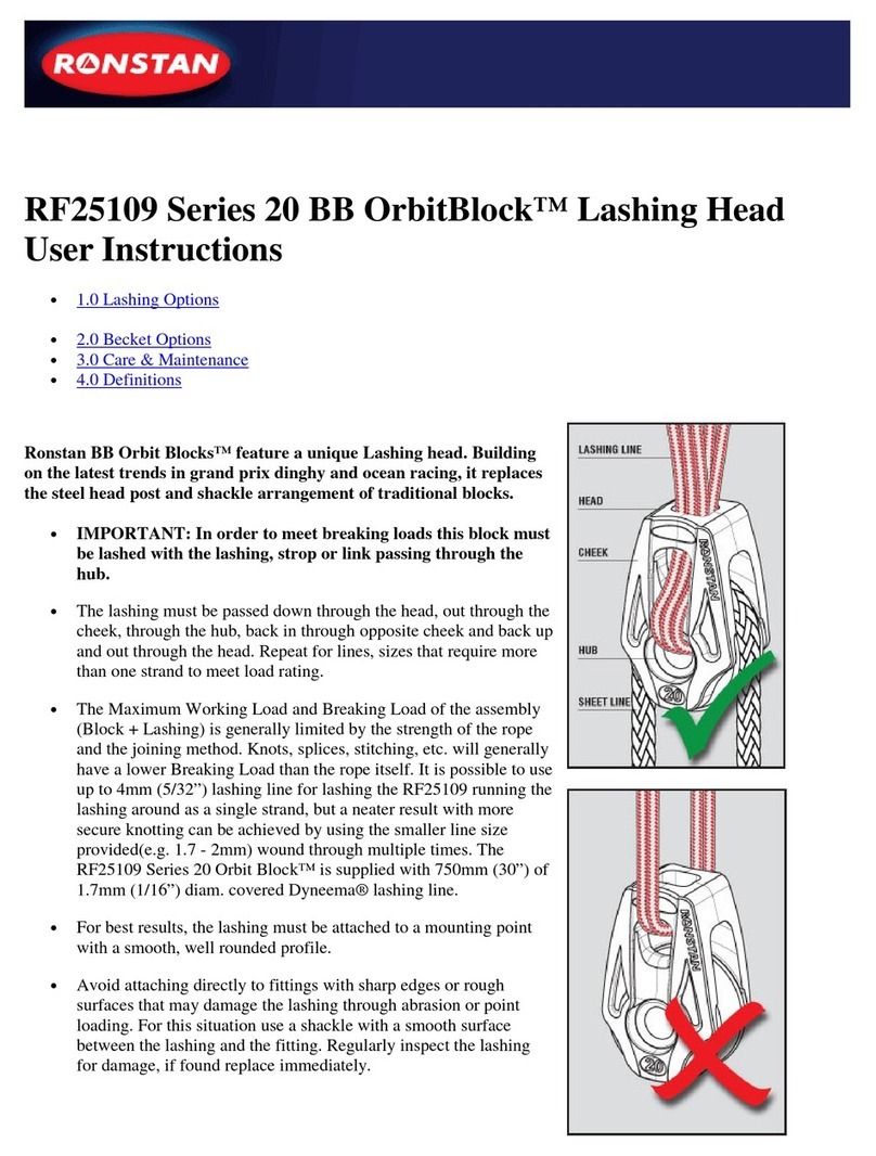
Ronstan
Ronstan BB OrbitBlock RF25109 Series User instructions
Daikin
Daikin VRV 5 Installation and operation manual
