TraffiCalm M75-DE0TS-CTLA User manual

Use and Operation Guide
PN 029-05227-0000 rev B
Applies to the following assemblies:
M75-DE0TS-CTLA
M75-DE0TS-CLTE
This guide is designed to asssist in the installation of
• System Design
• Theory of Operation
• Installation
• System Configuration
• Validation Testing
• Maintenance
In addition to this guide, installation manuals and
supplements have been delivered with the product.
These are also available at Trafficalm.com/wwa.
TraffiCalm greatly appreciates your investment in our
solutions, if at any time you require additional assistance
feel free to give us a call at 855-738-2722
Wrong Way Warning System

2
⟨System Design⟩
Components:
The TraffiCalm™Wrong Way Warning Systems consist of these
basic elements:
• Controller (M75-DE0TS-0013)
• Collaborators (M75-SA300-CLBX)
• Power Supplies
• LED Sign Enhancement Rings or RRFBs
Additional accessories include
• Expanded-use power supplies (low temp, larger solar, etc)
• Internally-illuminated signs with LED enhancement rings
• other detection methods (loops, for example)
• Third party detection systems
System Layout
A single Wrong Way Controller works in conjuction with at least
one Collaborator to create a network that cover a road section
(typically a ramp) in wireless collaboration, resulting in timely
warning to any violating drivers
Some form of detection must be connected to either the
Controller or a Collaborator. Multiple forms of detection can be
combined across the platform.
The Controller and each Collaborator can be set up as flashing or
detecting, and layed out in any orientation on the road section.
Especially consider the position of the Controller to ensure it is
easily accessed in the event maintenance is required.

3
What it all looks like
⟨System Design⟩
Radar
(if equipped)
Collaborator
Controller
Enhanced
Wrong Way Sign
Reason we need
wrong way
mitigation

4
In anticipation of your project we supplied design guides (example
shown below) that itemized the hardware used per specific road
section (typically a ramp) and per post. This guide is critical to the
success of the installation and should be available for reference during
the planning and installation phases. After the installation, this guide
can be referenced during maintenance and, if needed, repair.
Recommendations
Units 1,2, 3 Install Collaborator w/ Meshnet radio, Radar, and
solar panel kits on new poles
Parts Needed:
3x M75-SA300-CLBE Collaborator w/ integrated 13Ah battery
3x M75-SA300-RDR0 Radar detector
3x M75-M75-SLRPN-030W 30W Solar panel and bracket
3x M85-R1640-AT00 16’ Aluminum Pedestal Pole Kit
Unit 4 Install WWA Controller w/ Meshnet radio, Radar,
external 120 VAC power supply. Locate on or near existing
street light for access to AC supply
Parts Needed:
1x M75-DETCA-M000 Wrong Way Alert Controller
1x M75-ACPWR-U060 120 VAC Controller power supply
1x M75-SA300-RDR0 Lite radar detector
Notes: Refer to installation guide for details on aiming
detector units. In short, all detecting units should be
mounted high on the post for maximum effectiveness and
minimize false detections; new posts are required. The
juxtaposition of nearby right-way trafc will necessitate
detailed radar aiming and conguration. All measurements
are approximate.
Wrong Way Alert System
Component Conguration
and Recommendations
Provided For:
Colorado DOT
Location: Wheat Ridge, Colorado
I70 WB Exit 266 @ Ward Rd
3
1
2
4
example of design guide/pictorial
The design guide portrays the functionality of our system and
how the specific components will need to be placed in order to
perform well for the given road section.
The design guide was created remotely, with information at
hand. Locally exclusive information may dictate change orders to
the design of the system, these should be noted and updated on
the design guide.
Note that the visualized detection aiming is approximate, further
in this guide we will cover detection theory.
⟨System Design⟩
5
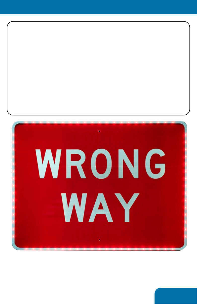
LED Sign Enhancements:
The supplied sign enhancements are made to install to any
Wrong Way or Do Not Enter sign manufactured to MUTCD
requirements. They can be highlighted in either red or white
LEDs and are designed to provide ample warning to any wrong
way driver in almost any condition, day or night.
The LED enhancements can be connected to any Controller or
Collaborator in the system.
LED flashing will only occur upon succesful detection of a wrong
way vehicle
⟨System Design⟩
LED intensity is hard to photograph, but
these things stand out when needed!

6
Before installing the system...
The three main goals of any wrong way mitigation system:
1. Detect Wrong Way Drivers (WWDs) in any condition
2. Prompt WWDs to self correct and safely turn around
Trafficalm has developed a proven system that can accomplish
all three with minimal hardware and stellar performance
Performance must be measured by two factors:
1. Ability to warn any wrong way driver
2. Ability to send undeniable evidence of a WWD’s activity to a
system or person that can act upon the reported activity
Wrong Way Alert has been developed to make installation not
only easy, but nearly foolproof. However, it is still important to
understand a few core concepts...
⟨Theory of Operation⟩
Radars and Other Detection
We use many “small” radar detectors to create up to 4 zones
of detection. While each zone can consist of a single radar, it is
highly recommended that two make up the zone.
The more radars and zones that are incorporated the more
accurate a system can be considered. It is entirely viable to
create a system with just one radar, but the chance for false
detections increase dramatically. Adding a second radar will
halve the occurance of false calls, a third will halve it again.
Typically, a complete system that can deliver at least a 99.5%
accuracy rate consists of 4 radars in two zones.
Third party detection methods can also be employed. Examples
of these systems are loop detectors, thermal cameras, and
advanced radars. System reliability is contingent on the design,
use, and user’s understanding of these devices.

7
Collaboration
The Controller wirelessly receives all the detection data from
the detectors. This information is validated by a collaboration
algorithm that determines whether a notification should be sent
or not.
How does it work? The system’s algorithm considers the
vehicle’s presence and distance travelled (determined by series
of detections). A real vehicle will have a predictable signature of
detection which can be relied upon for sending notification.
⟨Theory of Operation⟩
WRONG
WAY
WRONG
WAY
WRONG
WAY
WRONG
WAY
example of typical 2 zone, 4 radar setup
8
Introduction
It is beneficial to understand how the individual components
are deployed in the field, especially where maintenance will be
required.
In this section we will detail each component and notes on its
installation.
Typical installation procedure...
1. Affix LED enhancment ring to sign face (if needed)
2. Install Controller or Collaborator
3. Install supporting power supply (solar panel, battery box, AC
inverter, etc.)
4. Install Radar high on post, alternatively install third party
detection system according to manufacturer’s instructions
5. Install sign and LED ehnacement ring to post
6. Make all connections between devices
7. Power on Collaborators
8. Power On Controller
9. Configure System
⟨Installation⟩
Mounting Methods
Various methods can be used to mount our components. An
installation kit is supplied which contains bolts for mounting to square
posts and banding brackets for mounting to round posts or unusual
infrastructure. No banding or banding tool is supplied. Where banding
is used, it is recommended that 3/4” banding be double wrapped to
ensure maximum stability in windy and icy conditions.
Some of our solar panel brackets require large u-bolts (not supplied)
not readily available. It is highly recommended this be planned for and
purchased accordingly. They are the best possible way to mount our
solar panels to ensure years of trouble free service.
ALWAYS ensure the antennas have clear line of site
to the Controller!(!!!)
NOTE: It is prudent to take note of each Collaborator’s ID
number and location before installing on the post!
9
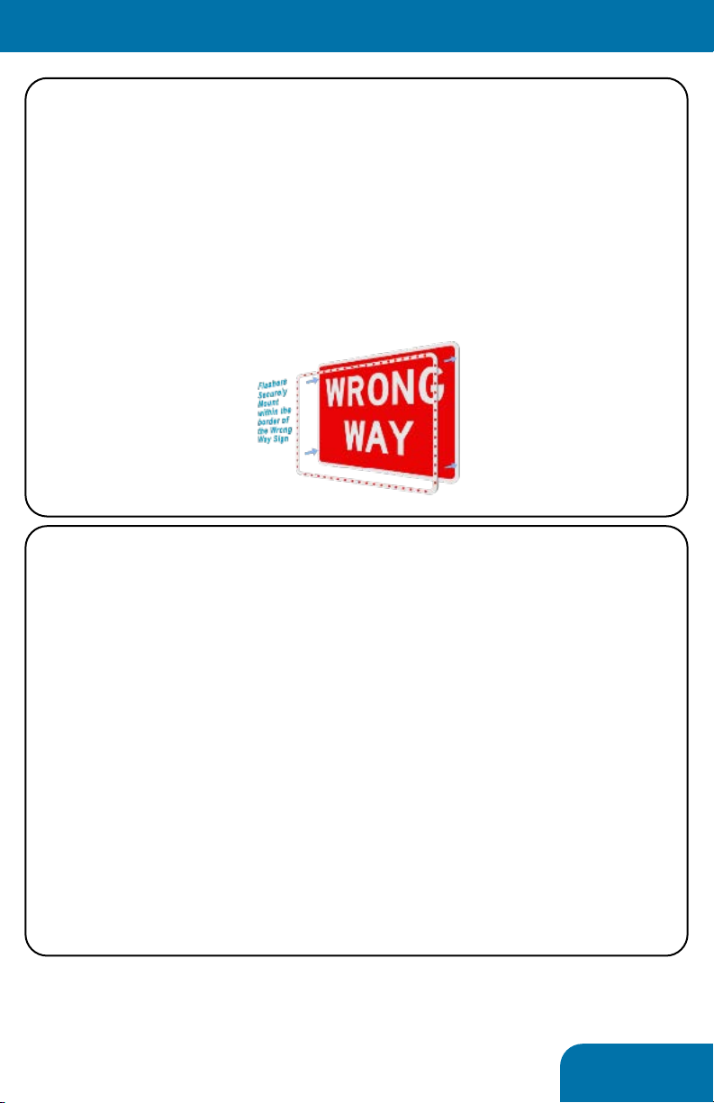
LED Enhancement Rings
The supplied LED enhancment rings (wrong way or do not
enter) are designed as a cohesive ring that affixes to the face of
the respective sign. A single wire exits the top left or right of the
ring; no hardware or cabling are visible on the back of the sign.
To attach the ring, peel and stick the addhesive backing to the
sign. It is highly recommended that the sign be cleaned with the
supplied alcohol wipes before adhering the ring.
⟨Installation⟩
⟨Installation⟩
Controller
Critical-The controller has two antennas that must be installed
before power is applied!
If utilized, the radar must be attached before power is applied
The controller should be located on the post or infrastructure
so that all supporting components can be connected with the
supplied lengths of cable and conduit.
It is also important to consider camera aiming. See the next
segment for more info
The controller features two mounting tabs, top and bottom, that
are spaced on 1” centers for mounting directly to square posts.
Alternatively, banding brackets can be used in the same location

10
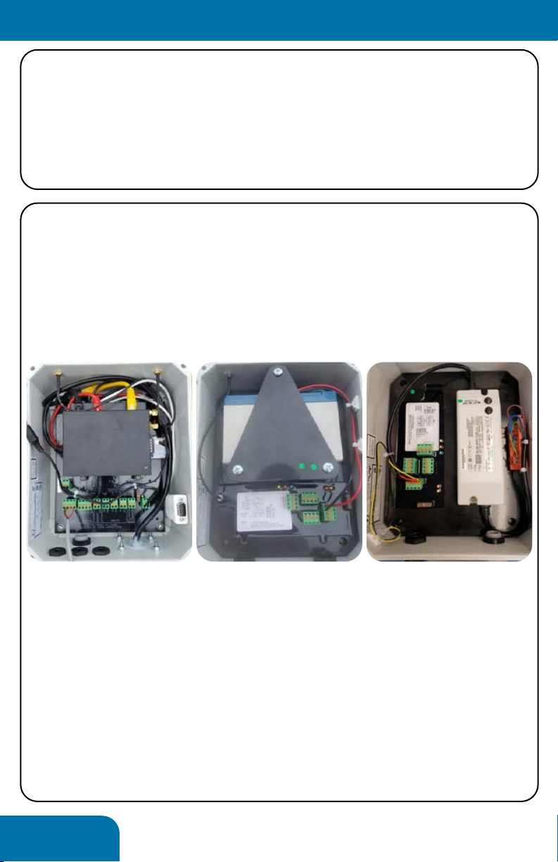
Power Supplies, cont’d
The Controller can operate on any 12V source supplying about 6
amps of power. We spec (and supply) the following options:
• Outdoor rated AC inverter
• Battery charger kit that can operate off timed street lamps
• Large solar kits to provide completely off-grid power
Many systems use a combination of power- AC at the Controller
and solar power at the Collaborators
Unlike the Controller, the Collaborators are configured for their
specific power type and feature built-in components to support
the supplied power.
AC Collaborators receive AC power terminated directly inside the
unit.
Solar powered units feature a 13Ah extreme temperature battery
built into the unit. A 20W, 30W, or 60W panel can be supplied to
charge the battery. All charging circuitry is integrated into the
unit. A single wire runs from the solar panel into the box.
Where solar power is utilized, ensure that the solar panels are
south-facing and angled at 45 (off of level). A calculation typical
to solar installation can be utilized to measure an exact angle
specific to your latitude.
⟨Installation⟩
example of solar setup, from the ground
11
Radars
Much of the system’s success or failure relies on the radar’s
aiming and configuration. Some of this will be a matter of trial
and error on every site, but some guiding principals will help...
The radar can detect a wrong way vehicle driving toward it or
away from itself. The configuration will designate the desired
function.
The radar should be mounted as high as possible on the post or
infrastructure. Height maximizes the unit’s ability to be aimed
correctly and to exclude periphery activity not constituting
wrong way driving.
Nothing (Controller, solar panel, signage, etc.) should obstruct
the immediate face of the radar.
As much as possible the radar’s view should be minimally
obstructed by nearby signage, buildings, or foliage. Such objects
can cause dead spots, reflections,
or small motions that will
obfuscate functionality.
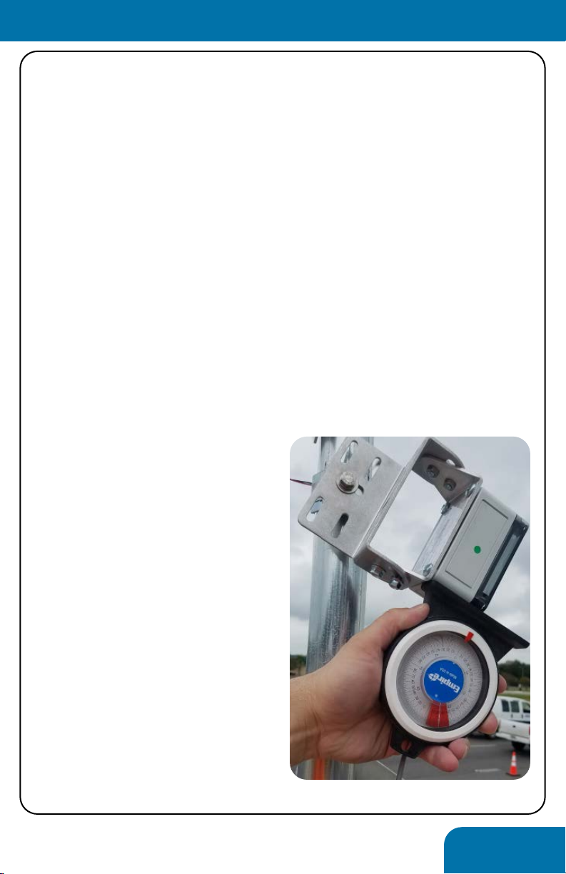
The radar mounting bracket
accomodates a great angular
adjustment of the radar. As
shown at right, it can be rotated
both up and down, as well as left
and right to achieve an accute
(45, typically) aiming at the
roadway.
You want the radar to spotlight
a small section of roadway about
60’ (183m) in front of the post.
Higher aiming (broadcast) will
produce false detections that
are difficult to exclude with
configuration settings.
⟨Installation⟩
12
Signage
With the LED enhancement applied the sign will mount as any
other road sign. It is important that the cable exit the ring at the
top left or right corner.
Hardware to mount the signs is not supplied, but readily
available at any hardware store or sign supply shop.
⟨Installation⟩
Making Connections
Within the Controller and Collaborator are labeled headers for
each connection. No other connections within the box will need
to be made, as these are all connected and tested at the time of
shipment. If applicable, the battery terminal block may need to
be connected.
Our components utilize quick capture connections. To terminate
a wire, strip the wire back 10mm, dpress the orange tab on the
terminal, insert the wire, and release the tab. The whole green
connector block may be removed to ease connections.
All the Collaborators in a group can be powered on at any
time. However, due to a 2 hour security time out, it is advised
that the Controller be powered on in the final stage of
installation.
Controller Solar Collaborator AC Collaborator

13
Overview
Configuration is compatible with any wi-fi enabled device. This
includes smartphones, tablets, and PCs.
2-5 minutes after being powered on, the Controller will activate
a wi-fi network (identified as a unique id containing WWA”)
available for connection. Connect to this network as any other,
through your device’s wi-fi settings. You will need to use the
following password:
Tr@ffiCalm (case sensitive)
The device will warn you that no internet connection is available;
this is expected and should be excused. Open the web browser
of choice (Explorer, Chrome, Safari, and Edge have been tested
functional) and navigate to:
Setup.trafficalm.com
You will be prompted for the following password:
Tr@ffiCalm
The setup wizard will take you step by step through the system
configuration and setup.
A configuration guide is supplied seperately to ensure the entire
process can be planned ahead of the installation.
⟨Configuration⟩
14
Validation Testing
After setup has been finalized it is important to test the system.
The first phase of testing should be to observe any sources of
radar “noise” and to adjust the settings and aim to exclude this
noise.
The system can be “reversed” to test on live “right-way” traffic.
Alternatively, and preferably, the road section should be shut
down and live wrong-way testing be performed. We have
developed the following test script for reference...
⟨Testing⟩
Wrong Way Alert Test Script
released: 20190815
Run description Pass? Time to Notify
Lane 1
Lane 2
Lane 3
Lane 1+2
Lane 2+3
Lane 1+3
Notes
This test can be expanded to as many lanes of entry as necessary, we have limited it to three (3)only for
reference. Where alternative methods of detection are utilized (loops, push buttons, etc) the test will
still be effective, though additional hardware settings may be required on the detection hardware. We
have seen this test expanded upon, with different vehicle sizes noted, expanded speeds added, and
additional environmental influences (trains in motion, for example) considered, consider this a starting
point for your own tests.
Notes
Procedure- Where RSUT closure is not permissible; it is feasible to test the system off of active, right way
traffic. The control of speed and traffic volume is inherently impossible in this scenario. System test will
rely on sufficient observation of traffic activating the system from specific lanes of entry. It is advised
that tests occur during hours that traffic is expected to be low; specifically, gaps between passing
vehicles results in improved accuracy and is most indicative of an average wrong way event. With the
assistance of TraffiCalm systems team, these tests can be performed remotely. To perform this test, the
system will be set up in “reverse” of its final configuration. For example, a system consisting of 2 radars
in the Pre-Alert Zone and 2 radars in the Alert Zone, all detecting approaching traffic (wrong way traffic)
will be configured with 2 radars in the Confirmation Zone and 2 radars in the Alert Zone, all set to detect
receding traffic. It is critical that the detection aiming remains identical throughout the test to ensure
proper operation in Wrong Way mode. Once the test is complete, the system can be configured to
wrong way mode by reversing the changes set.
Where ramp closure is not possible

15
⟨Testing⟩
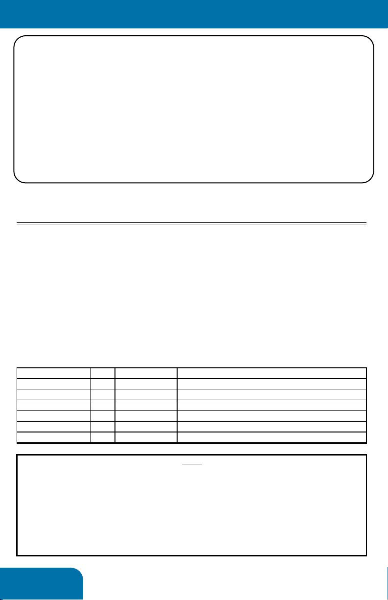
Wrong Way Alert Test Script
released: 20190815
Run description Pass? Time to Notify
10mph, lane 1
25mph, lane1
35mph, lane1
45mph, lane1
10mph, lane 2
25mph, lane2
35mph, lane2
45mph, lane2
10mph, lane 3
25mph, lane3
35mph, lane3
45mph, lane3
25mph, Cross Lanes
Given the variability of ramps and roadways that Wrong Way Alert can cover, it is important to properly
test and verify system functionality. In our experience, a concise test plan results in effective
performance measures that can be relied upon for real world monitoring of dangerous wrong way
events. This script is the result of working with dozens of transportation engineers on real projects and
we feel it is comprehensive, but local knowledge and regulations should be considered when
implementing your own test plan. Note that this procedure is intended to be used after the system has
been configured. All tests should result in a full notification and warning devices being illuminated.
Procedure- Per governing guidelines, the road section under test (RSUT) shall be closed to permit
sufficient and safe passage of a single vehicle traveling the wrong direction at up to 45mph through all
potential lanes of entry; this may include medians and shoulders. The result should be twofold- complete
coverage resulting in notifications being sent from any possible wrong way driving scenario, and no false
detections after the RSUT is opened to live traffic. If a fail occurs, it is (typically) reasonably acceptable to
adjust radar aiming and configuration, and then restart the test.
Notes
Where ramp closure is feasible (recommended)

16 www.trafficalm.com/wwa
Warranty Statement
Applies to: All TraffiCalm supplied Wrong Way Alert System devices
TraffiCalm Systems provides the following warranty for its traffic calming
solutions whether sold directly by TraffiCalm or by an authorized TraffiCalm
distribution partner.
• TraffiCalm Systems warrants the product, excluding batteries, will be
free of defect in materials and workmanship for a period of five (5) years
beginning on the day the end user receives the product. Warranty is
only valid if the product is ineffective for its intended purpose due to
defects in materials or workmanship.
• Warranty is only valid if the product is installed, operated and
maintained in accordance with the manufacturer’s instructions and
recommendations (available upon request).
• TraffiCalm’s sole responsibility, and the purchaser’s and users’
exclusive remedy, shall be that TraffiCalm will either repair or furnish
replacements for defective parts.
• Replacement parts will carry the unexpired warranty of the parts they
replace. Any repairs conducted on out-of-warranty items will carry a 90
day warranty.
• Claims made under this warranty will be honored only if TraffiCalm is
notified of a failure within the warranty period, reasonable information
requested by TraffiCalm is provided, and TraffiCalm is permitted to verify
the cause of the failure.
• TraffiCalm assumes no liability for any incidental or consequential
damages, in any way related to the product regardless of the legal
theory on which the claim is based.
• TraffiCalm Flashing Sign Systems are designed, tested, and warranted to
operate as a matched component system. The warranty is voided if all
system components for controllers, collaborators, and LED rings are not
TraffiCalm equipment and third party devices are substituted without
prior written approval from TraffiCalm.
This warranty does not cover damage resulting from:
o Accidents, vandalism, impact with a foreign object, or acts of God.
o Product modifications made by someone not authorized by TraffiCalm
o Failure of Customer to follow TraffiCalm’s published operating instructions,
o Failure to follow TraffiCalm’s published site selection and installation instructions,
o Removal or relocation of the unit,
o Electrical work external to the unit, virus/hacker activity, and external computer errors.
THIS WARRANTY IS MADE IN LIEU OF ALL OTHER WARRANTIES AND
CONDITIONS, EXPRESS OR IMPLIED, INCLUDING BUT NOT LIMITED TO THE
IMPLIED WARRANTIES AND CONDITIONS OF MERCHANTABILITY.
This manual suits for next models
1
Table of contents
Other TraffiCalm Safety Equipment manuals


Popular Safety Equipment manuals by other brands


LAHTI PRO
LAHTI PRO L30423 user manual

ASO Safety Solutions
ASO Safety Solutions Sentir Safety Contact Bumper instruction manual

Tractel
Tractel rollclamp Installation, operating and maintenance manual

Crewsaver
Crewsaver Euro 100N owner's manual

Capital Safety
Capital Safety DBI SALA PROTECTA EN361 Instructions for use and maintenance

Protecta
Protecta PRO-Line 1200101 manual


