Trailboss QTHN454L User manual
Towbar Fitting Instructions
To Suit HONDA CR-V RW CL4
Part Number QTHN454L
Rating 1500/100 kg
PLACE THESE INSTRUCTIONS IN THE VEHICLE’S GLOVEBOX AFTER INSTALLATION IS COMPLETED
Cequent Customer Service
Ph: 1800 812 017 Fax: 03 9898 3299
Post: PO Box 4050, Dandenong South VIC 3175
Rev: A Page 1 Issue Date: 04/04/2018
FOR TRAILER TOWING PURPOSES ONLY
For towing capacity details please refer to vehicle owner’s
manual or to the manufacturer. Overloading can void your
warranties.
WARNING:
1. Do not, drill, cut, weld or otherwise modify the tow bar.
2. If you are using electric welding on a motor vehicle, always check that the vehicle is not equipped with electronic
engine or instrument management equipment. Failure to do so could destroy any onboard computers. If in
doubt, check with the vehicle's manufacturer.
3. The high tensile fasteners supplied with this product were used to achieve the specified rating. If replacement is
required ensure that fasteners of the same rating & quality are used. Contact an authorised Trailboss dealer if
further information is required.
4. If TBM is used in inverted position tow ball may make contact with rear tailgate when lowered, which could cause
damage.
General:
1. Ensure all hardware items have been included refer to assembly diagram.
2. It is recommended that the instructions are read through and completely understood before making any attempt
to fit this product.
3. Be wary of any changes to vehicle designs or other accessories that may conflict with the installation of this
product.
4. Before drilling ensure that the area is clear of fuel, electrical & other components.
5. All holes drilled into the body panels shall have all burrs & swarf removed then coated with a suitable rust
preventative paint.
6. For vehicles that require the bumper to be cut. Ensure cut out area is in correct position on the vehicle prior to
cutting the bumper.
7. The high tensile fasteners supplied with this product were used to achieve the specified rating. If replacement is
required ensure that fasteners of the same rating & quality are used. Contact an authorized Trailboss dealer if
further information is required.
8. Ensure that all hardware is fastened to torque list below check fasteners on regular basis.
9. Tow bar load rating sticker provided with this product shall be conspicuously located on inside rear end of the
driver's door. (See diagram below).
10. Trailboss recommends that you check your tow ball to ensure that it complies with the Australian standards
AS 4177.2.
11. PLEASE NOTE: It is advised to remove your LUG or TBM when not actually towing so as to produce a clear view
of the vehicles registration plate if obscured, and to also provide maximum available departure angle
Tow bar Maintenance and Care.
Trailboss recommends that bolt torque’s, as listed below, are routinely and regularly inspected and checked for correct
tension. Replace any worn or defective parts.
We recommended to remove Tow Ball Mounts (TBM’s, tongues or lugs) when not being used for any considerable length
of time.
So as to avoid injury, when not towing it is suggested that the tongue, Pull Pin and R-clip are removed then stored in a
safe, clean and dry place, away from excessive moisture.
Hitch Pull Pins and spring “R” clips are regularly checked for proper installation. Replace any worn or defective parts.
Place load rating sticker
inside driver’s door here
RECOMMENDED ASSEMBLY TORQUE LISTING
Diameter Grade 8.8 Bolt
M6 9.5 Nm
M8 21.7 Nm
M10 43.4 Nm
M12 77.3Nm
M14 146 Nm
M16 189.8 Nm
Towbar Fitting Instructions
To Suit HONDA CR-V RW CL4
Part Number QTHN454L
Rating 1500/100 kg
PLACE THESE INSTRUCTIONS IN THE VEHICLE’S GLOVEBOX AFTER INSTALLATION IS COMPLETED
Cequent Customer Service
Ph: 1800 812 017 Fax: 03 9898 3299
Post: PO Box 4050, Dandenong South VIC 3175
Rev: A Page 2 Issue Date: 04/04/2018
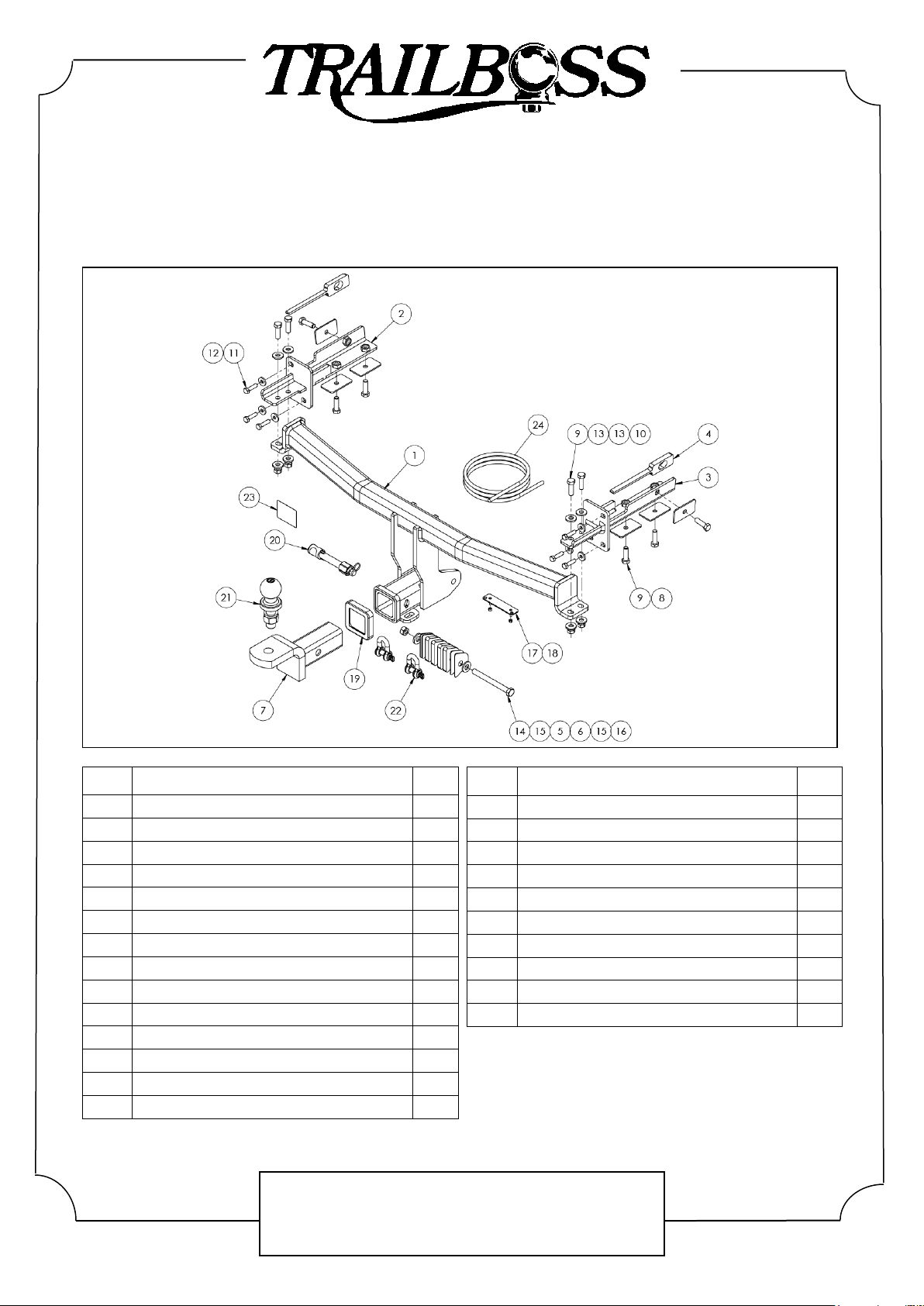
ITEM
DESCRIPTION
QTY
15
WASHER PLAIN 1/2X1-1/8X16G
2
16
NUT HEX HD M12 X 1.25P G8
1
17
VE PLUG BRACKET
1
18
NUT NYLON LOCK HEX HD M4X0.7P G8
2
19
HITCH BOX COLLAR COVER
1
20
SILENT HITCH PIN –SILVER
1
21
50MM TOWBALL
1
22
10MM “D”SHACKLE
2
23
ACRYLIC COMPLIANCE LABEL
1
24
WIRING LOOM
1
ITEM
DESCRIPTION
QTY
1
HONDA CRV WELDED ASSEMBLY
1
2
SIDE ARM LHS
1
3
SIDE ARM RHS
1
4
SIDE ARM SPACER
2
5
TOW HOOK SPACER THICK
4
6
TOW HOOK SPACER THIN
4
7
TRAILER BALL MOUNT
1
8
WASHER PLATE
6
9
SETSCREW HXHD M10X35X1.5PG8.8
10
10
NUT HEX HD M10X1.5P G8
4
11
SETSCREW HEX HD M8X30X1.25P G8.8
6
12
WASHER PLAIN M8 X 22 X 3
6
13
WASHER PLAIN M10 X 25 X 3
8
14
BOLT HEX HD M12 X 120 X 1.25P G8.8
1

Towbar Fitting Instructions
To Suit HONDA CR-V RW CL4
Part Number QTHN454L
Rating 1500/100 kg
PLACE THESE INSTRUCTIONS IN THE VEHICLE’S GLOVEBOX AFTER INSTALLATION IS COMPLETED
Cequent Customer Service
Ph: 1800 812 017 Fax: 03 9898 3299
Post: PO Box 4050, Dandenong South VIC 3175
Rev: A Page 3 Issue Date: 04/04/2018
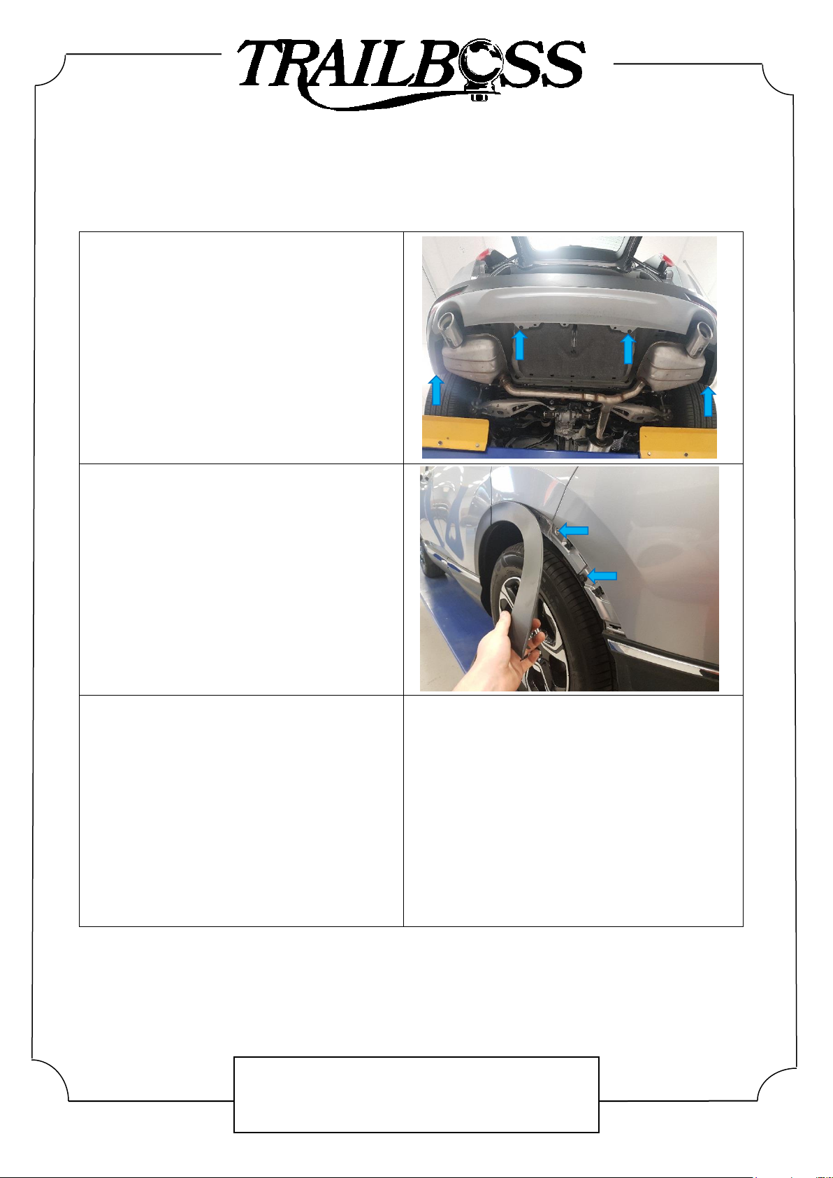
1. On the LHS of the bumper, remove 2 x torx
head screws from perimeter of boot opening.
Repeat for RHS.
2. On the LHS of vehicle, remove 2 x screws
from inside wheel arch on mudflap and 1 x
scrivet from underside of mudflap. Remove
mudflap and set aside.
Repeat for RHS.
3. On the LHS wheel arch, remove 1 x Phillips
head screw located behind mudflap (now
removed).
Repeat for RHS.
Towbar Fitting Instructions
To Suit HONDA CR-V RW CL4
Part Number QTHN454L
Rating 1500/100 kg
PLACE THESE INSTRUCTIONS IN THE VEHICLE’S GLOVEBOX AFTER INSTALLATION IS COMPLETED
Cequent Customer Service
Ph: 1800 812 017 Fax: 03 9898 3299
Post: PO Box 4050, Dandenong South VIC 3175
Rev: A Page 4 Issue Date: 04/04/2018
4. On the underside of the bumper, remove 2 x
screws and 2 x scrivets.
5. On the LHS of vehicle, carefully unclip and
remove wheel arch trim from vehicle.
Remove 1 x screw and 1 x scrivet from behind
wheel arch cover (now removed).
Repeat for RHS.
6. Carefully peel back bumper from corners and
remove, ensuring to disconnect any attached
wiring.
Set bumper aside.
Towbar Fitting Instructions
To Suit HONDA CR-V RW CL4
Part Number QTHN454L
Rating 1500/100 kg
PLACE THESE INSTRUCTIONS IN THE VEHICLE’S GLOVEBOX AFTER INSTALLATION IS COMPLETED
Cequent Customer Service
Ph: 1800 812 017 Fax: 03 9898 3299
Post: PO Box 4050, Dandenong South VIC 3175
Rev: A Page 5 Issue Date: 04/04/2018
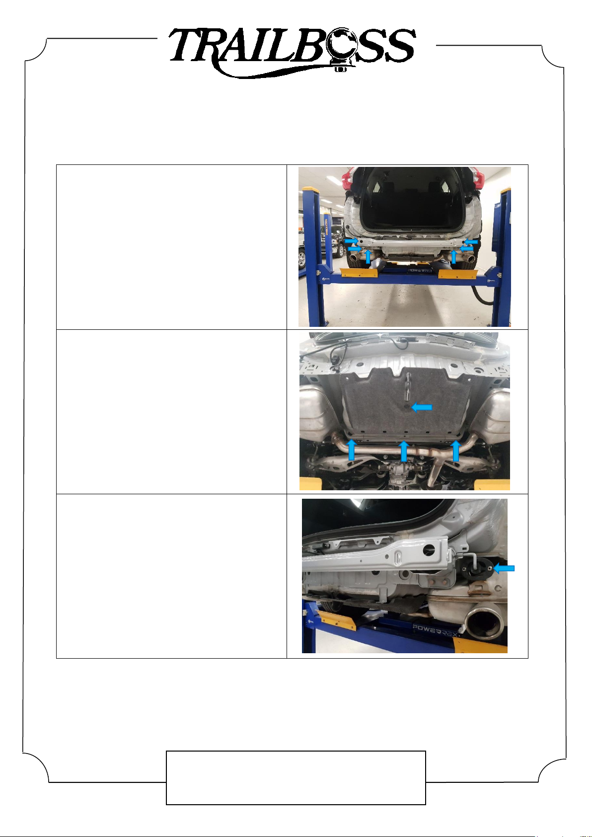
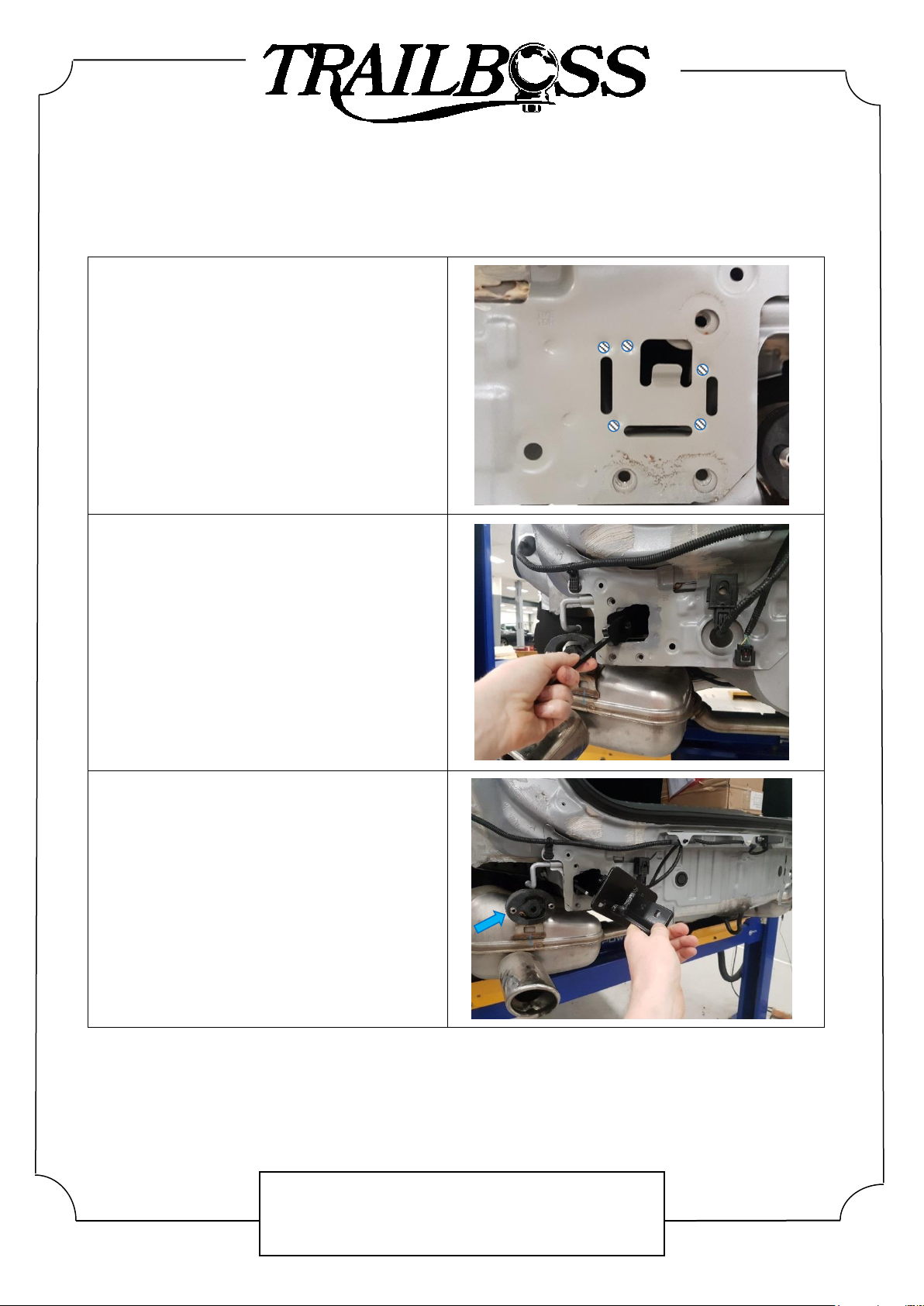
7. Remove impact beam via 3 x hex head bolts
per side. Discard impact beam and bolts.
8. Remove cover underneath vehicle via 2 x
flange nuts and 2 x scrivets.
Set aside for later.
9. Lower exhaust on both sides of vehicle (if
equipped) by removing from exhaust mounts.
Support exhaust once lowered.
Towbar Fitting Instructions
To Suit HONDA CR-V RW CL4
Part Number QTHN454L
Rating 1500/100 kg
PLACE THESE INSTRUCTIONS IN THE VEHICLE’S GLOVEBOX AFTER INSTALLATION IS COMPLETED
Cequent Customer Service
Ph: 1800 812 017 Fax: 03 9898 3299
Post: PO Box 4050, Dandenong South VIC 3175
Rev: A Page 6 Issue Date: 04/04/2018
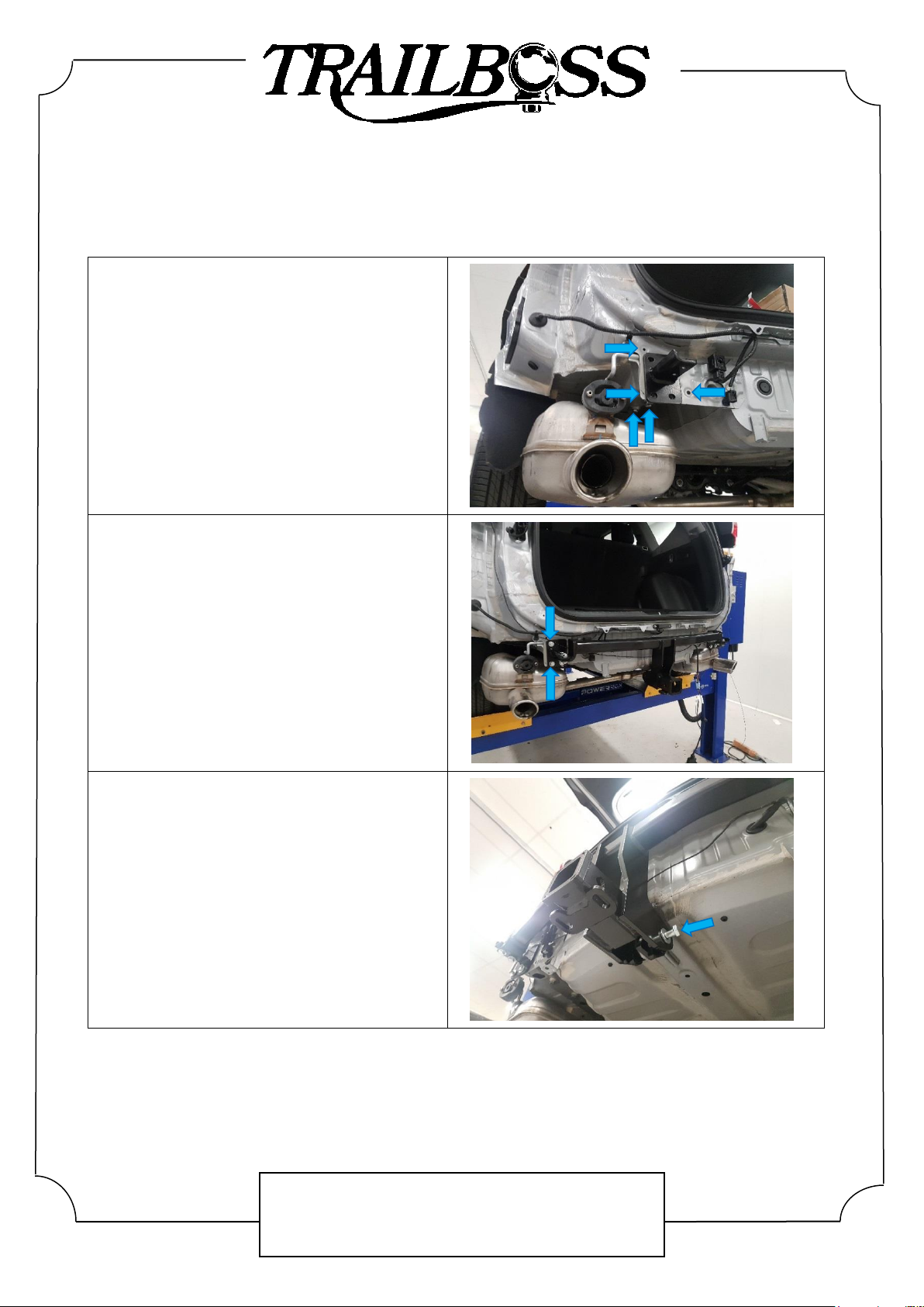
10. Using the 5 x location marks shown on the
rear panel chassis opening, drill 5 x 14mm
holes to remove metal sheeting.
Once cut, clean any burrs or sharp edges
using a file.
11. Insert spacer plate into LHS chassis rail
opening (now cut) along the LH face of
chassis.
Hold spacer in place by partially pushing M10
x 35mm bolt complete with 1 x M10 washer
plate from outside chassis rail into chassis.
12. Insert LH side arm (refer to exploded view)
into chassis rail. Align nut on the sidearm with
the spacer plate previously inserted (Step 11)
and loosely secure with the M10 bolt partially
inserted.
Repeat steps 11 and 12 for RHS.
Towbar Fitting Instructions
To Suit HONDA CR-V RW CL4
Part Number QTHN454L
Rating 1500/100 kg
PLACE THESE INSTRUCTIONS IN THE VEHICLE’S GLOVEBOX AFTER INSTALLATION IS COMPLETED
Cequent Customer Service
Ph: 1800 812 017 Fax: 03 9898 3299
Post: PO Box 4050, Dandenong South VIC 3175
Rev: A Page 7 Issue Date: 04/04/2018
13. On LH side arm, loosely secure with 3 x M8
bolts complete with 1 x M8 washer per bolt to
the rear panel.
Additionally, loosely secure LH side arm to
underside of chassis rail via 2 x M10 x 35mm
bolts complete with 1 x M10 washer plate per
bolt.
Repeat for RHS.
14. Lift towbar up to side arms and loosely secure
the LHS with 2 x M10 x 35mm bolts complete
with 2 x M10 washers and 1 x M10 nut per
bolt.
Repeat for RHS.
15. Secure towbar to centre recovery hook via 1 x
M12 bolt complete with 2 x M12 washers and
1 x M12 nut. Insert spacer plates provided
onto bolt between tow hook and dropper until
a tight fitting is achieved.
NOTE: Not all spacer plates may be used.
Tighten all fasteners to the torques listed
below:
M8 x 1.25 x G8.8: 22 N.m
M10 x 1.5 x G8.8: 44 N.m
M12 x 1.25 x G8.8: 89 N.m

Towbar Fitting Instructions
To Suit HONDA CR-V RW CL4
Part Number QTHN454L
Rating 1500/100 kg
PLACE THESE INSTRUCTIONS IN THE VEHICLE’S GLOVEBOX AFTER INSTALLATION IS COMPLETED
Cequent Customer Service
Ph: 1800 812 017 Fax: 03 9898 3299
Post: PO Box 4050, Dandenong South VIC 3175
Rev: A Page 8 Issue Date: 04/04/2018
16. Identify the centreline of the inside of the
bumper. Mark and cut a 90mm wide by 70mm
long rectangle, as measured from the bottom
edge of the bumper.
Remove any burrs after cut.
17.On the cover removed in Step 8, identify the
slot allocated for the factory tow hook. Mark
and cut a 90mm wide by 90mm long square,
as measured from the bottom edge of the
cover near the slot.
18.Mark out and drill 2 x ø5mm holes 69mm apart
on bumper skin to support plug bracket.
19.Reinstall bumper and components following
Steps 1–8 in reverse (excluding Step 7).
90mm
70mm
90mm
90mm

Wiring Loom Fitting Instructions
To Suit Honda CR-V
Part Number 101866-WL
Page 1 of 3 Issue Date 15-02-18
Cequent Customer Service
Ph: 1800 812 017 Fax: 03 9797 3299
Post: PO Box 4050, Dandenong South VIC 3175
Wiring Loom Installation Instructions
Honda CR-V
Part No: 101866-WL
Tail Harness Length Required: 400mm
RPA Override Switch Part No: 04836 (If Fitted)
Wiring Loom Installation Time: Approx 90 Mins

Wiring Loom Fitting Instructions
To Suit Honda CR-V
Part Number 101866-WL
Page 2 of 3 Issue Date 15-02-18
Cequent Customer Service
Ph: 1800 812 017 Fax: 03 9797 3299
Post: PO Box 4050, Dandenong South VIC 3175
1. Disconnect the negative battery terminal.
2. Pull the lever and fold down the rear passenger seats.
3. Remove the two cargo hooks.
4. Remove the luggage compartment front carpet trim.
5. Remove the floor carpet cover.
Note: For 7 seat variant, remove the 3rd row seats.
6. Remove the plastic trim from behind rear seats.
7. Remove the spare wheel and the jack.
8. Pull away the weatherstrip, and remove the luggage compartment rear trim.
9. Remove lower trim along RHS interior.
10. Dislodge the bottom of the RHS ‘B’ Pillar.
11. Remove lower Dash Trim.
12.Dislodge the RHS cargo trim.
13.Remove the RHS upper cargo trim.
14.Fold carpet back to access vehicle grommet.
15.Remove the RHS tail lamp.
Repeat for LHS.
16.Remove the vehicle blanking grommet.
17.Feed the trailer wiring harness from inside to outside the vehicle, starting with the blue
connector.
18.From outside the vehicle, ensure the trailer wiring harness grommet is seated correctly.
19. Route the longer T-Patch along the bottom and up the LHS tail lamp.
20.Connect the tail lamp connector to the trailer wiring mating connector.
21.Repeat for RHS with the shorter T-Patch lead.
22.In the cargo interior, route the Trailer Harness up and across to the exposed cavity on
the RHS.
23.Connect the trailer harness to the ECU (04836) and mount in the location shown.

Wiring Loom Fitting Instructions
To Suit Honda CR-V
Part Number 101866-WL
Page 3 of 3 Issue Date 15-02-18
Cequent Customer Service
Ph: 1800 812 017 Fax: 03 9797 3299
Post: PO Box 4050, Dandenong South VIC 3175
Note: Ensure ECU connector is facing down.
24.Connect the trailer wiring ground ring terminal to the vehicle grounding point.
25.Continue routing the trailer harness toward the front of the vehicle.
26.Route the Trailer Wiring Harness along the lower RHS interior of the vehicle, following
existing wiring where possible.
27.Under the vehicle dash, locate the 22-way green connector above the fuse panel.
28.Disconnect it and connect the vehicle T-Patch in between.
29.Remove the indicated 20A fuse (1) and discard.
30.Insert the two supplied fuses into the Add-A-Fuse Adapter.
31.Insert the Add-A-Fuse Adapter into the previously removed fuse location.
Note: Ensure lead is pointing down.
32.Connect the trailer wiring harness to the Add-A-Fuse.
33.At the rear of the vehicle, secure the 7-pin Socket from the tail (400mm) to the towbar.
34.Route the tail harness up and across to the mating blue connector on the trailer wiring
harness.
35.Connect the tail harness 8-way connector to the trailer patch 8-way mating connector.
36.Apply silicone grease to waterproof the connector.
37.Test the trailer wiring harness function using a light board or multi-meter. Secure all
harnesses using cable ties (not supplied).
38.Re-fit all removed parts and secure all fasteners, ensuring there are no squeaks or
rattles.
39.Place the fitting instructions in the glove box after fitment.

FITTING INSTRUCTIONS
Silent Anti-Rattle Hitch Pin (PRO001)
Pro Series
PO BOX 4050, Dandenong South, VIC 3164
[email protected] I 1800 812 017
www.pro-series.com.au
• These fitting instructions are supplied to ensure
understanding of how the HITCH PIN should be fitted and
used correctly.
•Once installed, we recommend ALL instructions are kept and
placed in the vehicle glove box.
NOTE: Routine maintenance and inspection of the towbar &
HITCH PIN is required. Regularly inspect for wear and check
the tightness of the Hitch Pin. Follow instructions below to
retighten the nut when necessary.
*Do not tow with your vehicle if the R CLIP or the HITCH PIN is
loose or missing. Replacement parts are available from your
Pro Series Distributor.
Hitch Pin Nut
R-Clip
Hitch Pin
Fig 1. Silent Anti-Rattle Hitch Pin assembly
Fig 2. Installation of Trailer Ball Mount Fig 3. Silent Anti-Rattle Hitch Pin orientation
Insert Trailer Ball Mount (TBM) into towbar HITCHBOX, aligning hole in TBM SHANK with hole in HITCHBOX
(Fig 2).
Insert HITCH PIN through hole in HITCHBOX and hole in TBM SHANK; ensure
the LOCATORS are inserted into the NOTCHES in the HITCHBOX (Fig. 3).
STEP 1
STEP 2
Screw HITCH PIN NUT onto HITCH PIN ; tighten HITCH PIN NUT until finger
STEPSTEP 3
3 tight, ensuring TBM is restrained from movement.
Tighten HITCH PIN NUT by turning nut a further 1/8th of a turn in the
clockwise direction using a 24mm spanner (Fig. 4).
STEP 4
Install HITCH PIN R CLIP through the hole on the HITCH PIN (Fig. 1).
STEP 5
Step 4
Fig 4. Tightening of Silent
Anti-Rattle Hitch Pin Nut
Notches
Locators
STEP 3
Table of contents
Other Trailboss Automobile Accessories manuals

Trailboss
Trailboss TT163L User manual

Trailboss
Trailboss KM23L User manual

Trailboss
Trailboss QTHD519L User manual

Trailboss
Trailboss QT1122L User manual

Trailboss
Trailboss QTMA662L User manual

Trailboss
Trailboss QTBM115L User manual

Trailboss
Trailboss QTHD722L User manual

Trailboss
Trailboss QTHY263L User manual

Trailboss
Trailboss QT1134L User manual

Trailboss
Trailboss HN72L User manual


