Trailer Valet RVR12 User manual

OPERATING MANUAL
RVR12
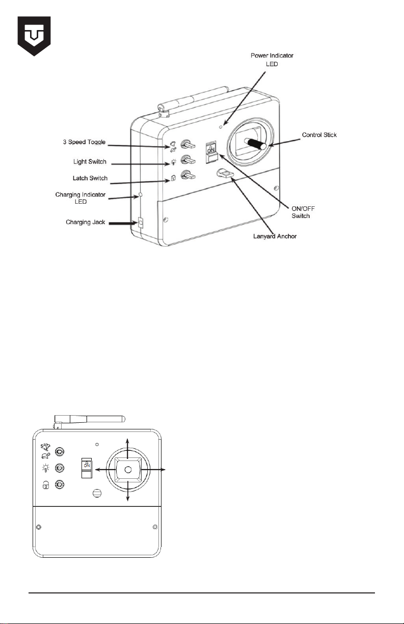
NOTE: The 3 Speed Toggle ranges from fast, moderate, and slow.
When operating the valet at slow speeds it may be necessary to switch to the moderate or fast
speed position on the toggle when turning at 90 degrees. Factors such as terrain and incline
may aect the maneuverability of the valet. Adjust the speed at your own discretion.
1. Switch the controller on and make sure the power indicator light turns on and the controller
beeps once. If this does not happen, check to make sure the batteries were installed correctly.
When the battery level in the controller becomes low the controller will begin to beep,
signaling you to replace or recharge the batteries.
2. To drive the valet, move the control stick in the desired direction.
WARNING: The control stick on the remote is
very sensitive and will cause the valet to move if
it is moved accidentally. When not using the
remote it is recommended that the power switch
is turned OFF.
NOTE: If the remote is not used for more than a
couple minutes it will start beeping as an
indicator that it is still in the ON position. This is
not an indicator of low battery level.
1
Controller Operation
1. Before turning on the valet, make sure that the tracks and bottom of the valet are free from
obstruction.
2. Turn the valet on using the ON/OFF button. There will be a short series of beeps and then
the power indicator LED around the Power button will illuminate to show the valet is on. The
Power Indicator LED may blink to indicate that the charge level of the battery is low.
3. Turn on the power switch on the radio controller and the power indicator LED will be green
and the transmit indicator LED will be red.
4. When towing, ALWAYS be cautious of the steering angle limitations of your trailer. Do not
over steer your trailer with the valet.
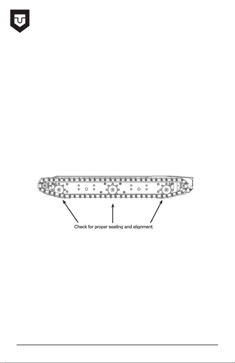
5. After lifting the valet o of the ground for any reason or taking it on and o of your trailer,
you must check to make sure that the sprockets are correctly seated on the tracks. If the
sprocket is not properly seated it could result in damage to the tracks.
6. Visually check the tracks for wear on the treads and wear on the inner plastic surfaces.
Also inspect for damaged or missing rotoclips as a result of driving over small rocks. Damaged
treads should be replaced before operating the valet.
NOTE: The circuit breaker reset button will trip if the valet is overloaded. To reset
the circuit breaker open the top cover to push the reset button down. If the reset button pops
back up wait 1 minute then try again.
2
Operating the Valet
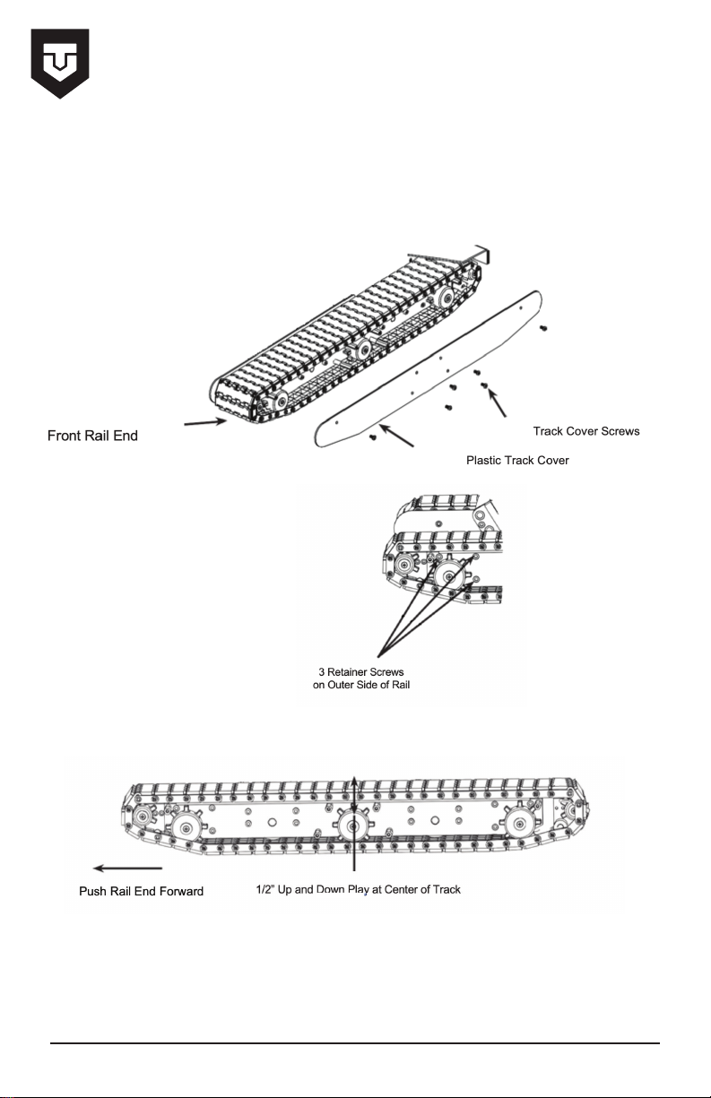
Track tension may need to be adjusted after several hours of use.
Follow the instructions below for each track.
1. Remove 6 track cover screws and remove the outside plastic track cover.
2. Loosen the three front rail end
retainer screws. It may be necessary to
rotate the large sprocket in order to gain
access to one of the retainer screws.
3. Push the rail end forward using a small pry bar to add tension to the track. There should be
about a 1/2” of play at the center of the track.
4. Tighten up all 3 retainer screws and reinstall the plastic track covers.
5. Repeat steps 1 thru 4 for the other track.
3
Adjusting The Track Tension
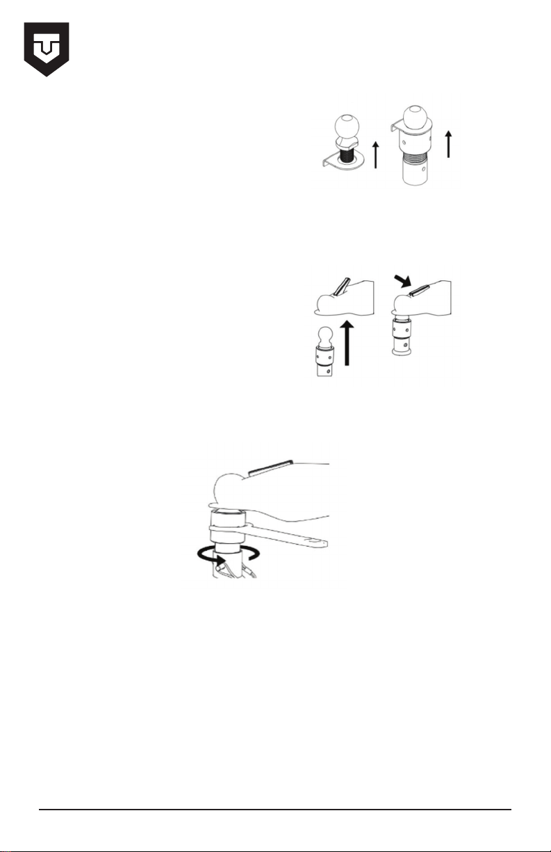
2. Place the Ball Base into the Base tower and secure with included pin. Then secure the Ball
Base Tower into the slot on top of the RVR in place of the Mount Bracket Tower.
WARNING! Failure to tighten the Locking Nut against the coupler may cause the ball to slip
out of the coupler.
4
Attach with Coupler Set
1. If the Coupling Plate is not already installed
with the Ball Base, detach the ball from the Base,
slip the Coupling Plate under the ball, and
reinsert into the Base. Secure tightly.
3. Raise the trailer tongue above the height of
the Hitch Ball in order to slip the ball into the
coupler and lock the with the coupler latch.
4. Using the Spanner Wrench, turn the Locking Nut counter clockwise until the nut is secured
flat against the coupler.
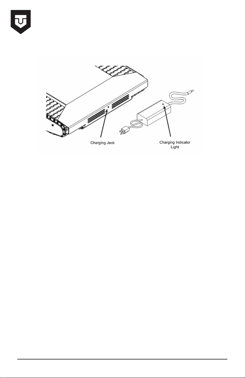
1. Before charging your valet, be sure the controller and valet are both turned OFF.
2. The charging indicator light on the charger should light up red once the charger is
connected properly. The valet will be fully charged once the charge indicator light turns green.
It is recommended to leave the valet charging when not in use.
3. Once the valet is fully charged, unplug the charger and turn the valet on. Then turn the
valet o for a few seconds and back on again. This will reset the valet. It is now ready to be
used.
5
Adjusting The Track Tension
6
Charging the Transmitter
WARNING: Only use the supplied charger to charge the transmitter when using
the supplied batteries or the following:
- 1200mAh Ni-MH or Ni-Cd ‘AA’ Rechargeable Batteries
The use of the transmitter charger with alkaline batteries installed can damage
the transmitter. Do not use the charger if alkaline batteries are installed in the
transmitter.
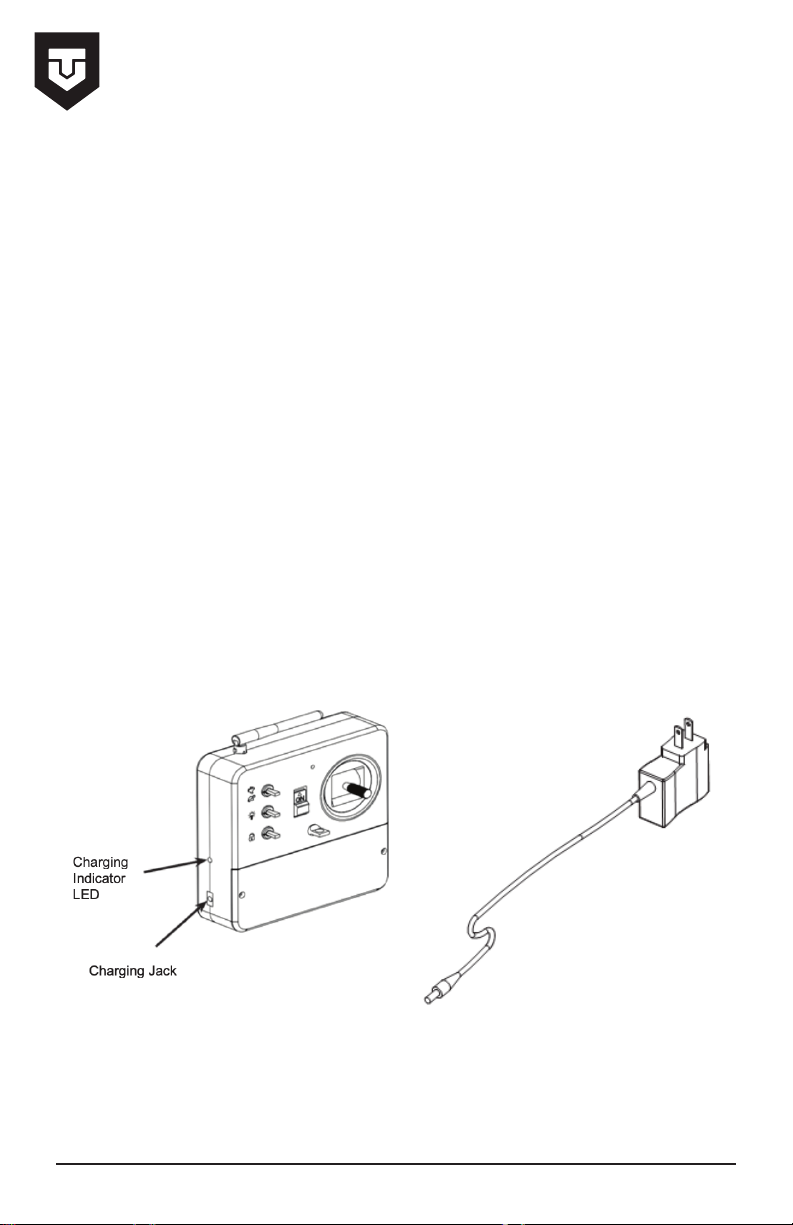
1. Plug the transmitter charger into a 110v AC wall socket.
2. Plug the connector from the charger into the charging jack on the transmitter. The
charging indicator LED, located on the side of the transmitter, will illuminate green indicating
the transmitter is charging. Once the transmitter is fully charged the charging indicator LED
will turn o.
3. The charging rate of the charger is 150mAh. When using the 1200mAh batteries that are
supplied, the controller requires a 2-4 hour charge when fully discharged (1200/150=8). If
using 2200mAh batteries, it will take approximately 4-6 hours to recharge (2200/150=14.6).

1. Remove 2 cover screws from the back of the transmitter case.
2. Replace old battery pack with a new battery pack.
NOTE: A battery tray is provided with the valet. It can be used with standard AA rechargable
batteries. Refer to section 2-9.
3A. Disconnect the shink wrapped battery
pack and remove the battery.
4A. Replace the batteries by purchasing a
new shrink wrapped battery pack or
installing the supplied battery tray and
purchasing 6 rechargeable ‘AA’ Lithium Ion
batteries.
5A. Reconnect the battery to the
transmitter circuit board.
6A. Re-install back cover and screws.
3B. Remove the 6 batteries and replace
with new rechargble ‘AA’ Lithium Ion
batteries.
4B. Re-install back cover and screws.
7
Replacing the Transmitter Batteries
AShrink Wrapped Battery Pack Battery Tray with 6 Rechargable
‘AA’ Lithium Ion Batteries
B
or
8
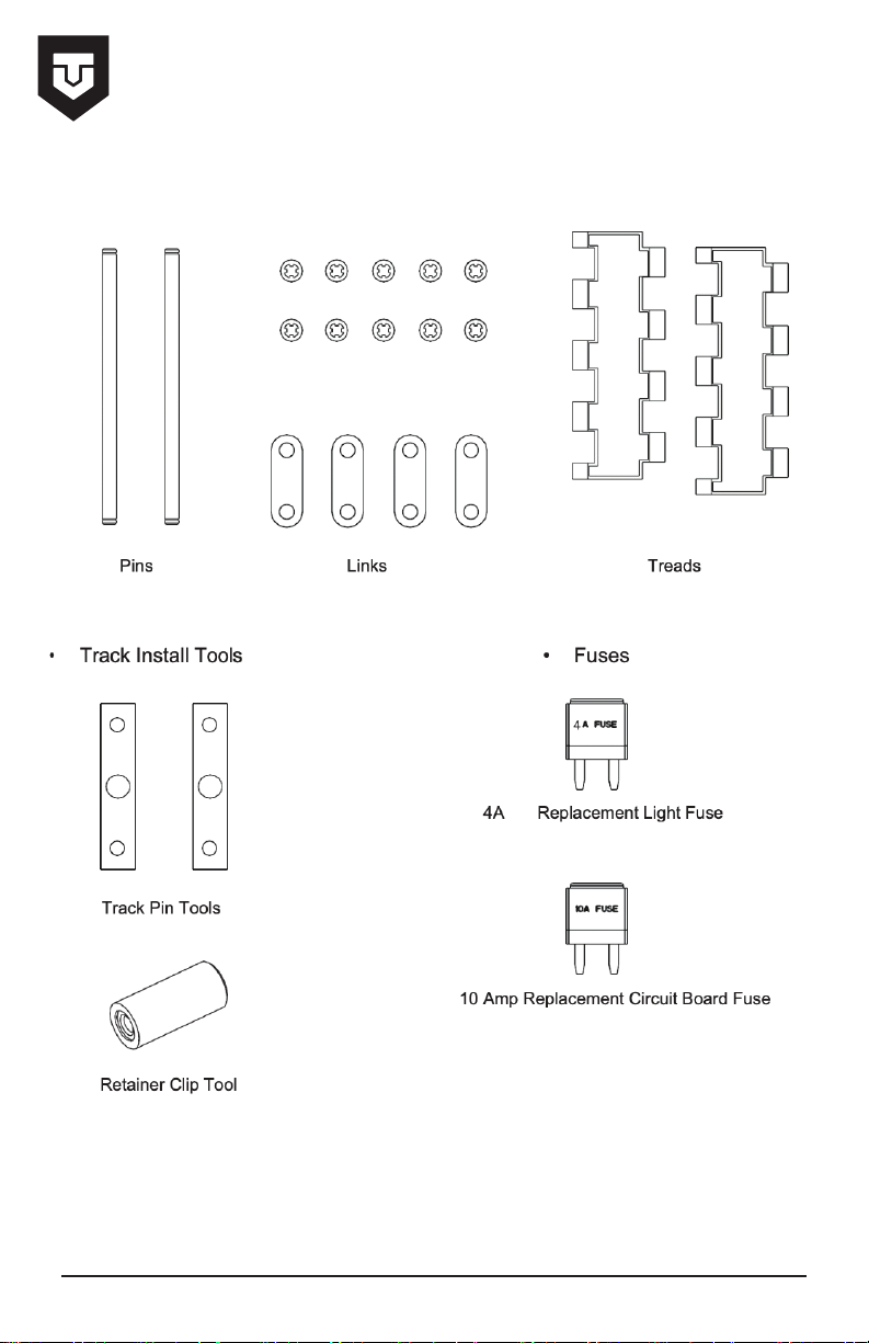
Spare TRACK Parts
Rotoclips
mp

The Track Tools are used to assist in the installation of new tracks.
NOTE: This section is intended to show how the tools are used only.
A detailed instruction guide is provided when purchasing new tracks. Refer to that instruction
guide when installing new tracks.
9
Track tools
When Rotoclip is properly installed in the track pin groove it should rotate freely inside of
the groove.
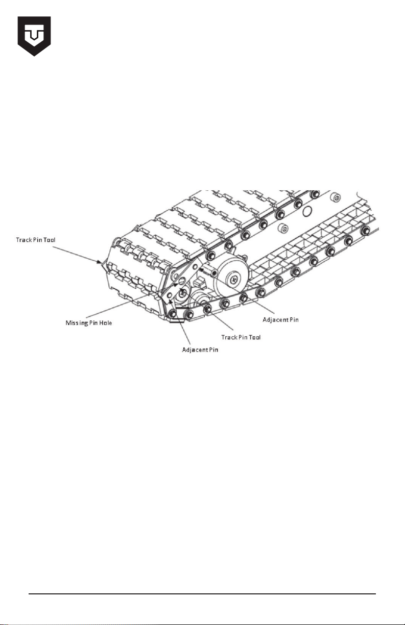
The Track Pin Tools are used to assist in the installation of new tracks when the tracks are too
tight making it dicult to align the pin holes.
Insert the Track Pin Tools on the inside and outside adjacent pins to the missing pin hole. Note: You
will need to hold these in place by hand.
10
Track tools
Other manuals for RVR12
1
Table of contents
Other Trailer Valet Automobile Accessories manuals


Popular Automobile Accessories manuals by other brands


ULTIMATE SPEED
ULTIMATE SPEED 279746 Assembly and Safety Advice

SSV Works
SSV Works DF-F65 manual

ULTIMATE SPEED
ULTIMATE SPEED CARBON Assembly and Safety Advice

Witter
Witter F174 Fitting instructions

WeatherTech
WeatherTech No-Drill installation instructions

TAUBENREUTHER
TAUBENREUTHER 1-336050 Installation instruction