manuals.online logo
Brands
  1. Home
  2. •
  3. Brands
  4. •
  5. Trane
  6. •
  7. Chiller
  8. •
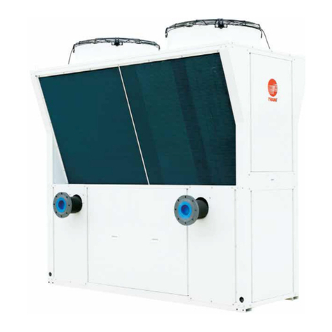
  9. Trane RAUP 250 Owner's manual

Trane RAUP 250 Owner's manual

Installation
Operation
Maintenance
Split System
Condensing Units
20-55 Tons
Models
RAUP 250
RAUP 300
RAUP 500
RAUP 600
RAUP 400
RAUP-IOM-R22/R407C
Rev.D
January 2020
690807890001
R22/R407C
- Standard Ambient
- High Ambient
(i)
Performance Data
Foreword
These installation operation and maintenance instructions are
given as a guide to good practice in the installation, putting, into
service, operation and periodic maintenance by the Trane Product
user. They do not contain the full service procedures necessary
for the continued successful operation of this equipment. The
services of a qualified service technician should be employed
through the medium of a maintenance contract with a reputable
service company.
Receiving/Handling
On arrival, inspect the unit before signing the delivery note. Specify
any damage on the delivery note, and send a registered letter of
protest to the last carrier of the goods within 72 hours of delivery.
Notify the local Trane Sales Office at the same time. The unit
should be totally inspected within 15 days of delivery.
If any concealed damage is discovered, stop unpacking the
shipment . Take photos of the damaged material if possible. Notify
the Carrier immediately by phone and registered mail. Notify the
local Trane Sales office. Concealed damage must be reported
within 15 days of delivery.
Warranty
Warranty is based on the general terms and conditions of The
Trane Company. The warranty is void if the equipment is repaired
or modified without the written approval of Trane, if the operating
limits are exceeded or if the control system or the electrical wiring
is modified. Damage due to misuse, lack of maintenance or failure
to comply with the manufacturer’s instructions or recommendations
is not covered by the warranty obligation.
(ii)
Contents
Performance Data
(i )
(i )
(i )
droweroF
ytnarraW
gnildnaH/gnivieceR
1erutalcnemoN
2 to 6tinUgnisnednoCnoT55-02ataDlareneG
Installation
7noitamrofnIlareneG
7etalpemaNtinU
7stnemeriuqeRnoitallatsnImooRenihcaM
7
snoitcennoClacirtcelE 10
10pu-tratStinU
Operation / Maintenance
12noitarepOtinU
12erudecorppu-tratslanosaeS
Maintenance
12ecnanetniaM
12ecnanetniaMylkeeW
13snoitcepsnIecnanetniaM
Compressor
14tatsomrehTgnidniWrotoM
14gnipiPdlofinaMrosserpmoC
15 to 17
Dimensional Data
Dimensional Data Condensing Unit
Trouble Analysis
Installation Checklist
Commissioning Log Sheet
Wiring Diagram
04 ot 23 margaiDnoitanimreT&citamehcS
18 to 22
41
42
Electrical Data 9
Isolation and Sound Emission (option)
1
MODEL NOMENCLATURE
1 2 3 4 5 6 7 8 9 10 11 12
R A U P 2 5 0 D 1 B 0 A
Digit No.1 = Product Type
R = Remote Condensing Unit
Digit No.2 = Product Type
A = Air Cooled
Digit No.3 = Product Type
U = Unit Up-Flow Air Flow
Digit No.4 = Development Sequence
P = Major Development
Digit No.5, 6, and 7 = Nominal Gross Capacity (MBH)
(Note: The alphabetic letter “O” is not used in Digit 6 or 7, only the number “0” is used.)
250 = 250 MBH 400 = 400 MBH 600 = 600 MBH
300 = 300 MBH 500 = 500 MBH
Digit No.8 = Electrical Rating / Utilization Range
D = 380-415V / 3Ph / 50Hz 3 = 230V / 3Ph / 60Hz
K = 380V / 3Ph / 60Hz 4 = 460V / 3Ph / 60Hz
Digit No.9 = Motor / Compressor Controls
1 = DOL (3-wire) Starter
Digit No.10 = Additional Design Sequence
B = Micro-P controller with R22
E = Micro-P controller with R407C
F = Carel pCO5 controller with R22
G = Carel pCO5 controller with R407C
H = Carel pCO5 controller with R410A (not for High Ambient)
J = Micro-P controller with R410A (not for High Ambient)
K = Micro-P controller + VFD Low Ambient Control with R22
L = Micro-P controller + VFD Low Ambient Control with R407C
M = Carel pCO5 controller + VFD Low Ambient Control with R22
N = Carel pCO5 controller + VFD Low Ambient Control with R407C
Digit No.11 = Factory Installed Options
(Note: The alphabetic letter “O” is not used in Digit 11, only the number “0” is used.)
0 = None 3 = Crankcase Heater
1 = Blue fin 4 = Copper fin
2 = Suction/Liquid shut off valve
D = Serviceable Filter Drier + Shut-off Sight Glass+ Ship Loose Solenoid V+ Crankcase + Coil Standard
E = Serviceable Filter Drier + Shut-off Sight Glass+ Ship Loose Solenoid V+ Crankcase + Coil Blue Fin
F = Serviceable Filter Drier + Shut-off Sight Glass+ Ship Loose Solenoid V+ Crankcase + Coil Copper Fin
S = Special (Write additional option in PO note)
Digit No.12 = Ambient Indicator
A = Standard Ambient with R22, R407C for 50 and 60 Hz, Standard Ambient with R410A for 50 Hz only
B = High Ambient (R22, R407c) for 50 Hz only.
Note
“K”, “3”, and “4” in Digit No. 8 cannot applicable with “B” in Digit No.12
“H” and “J” in Digit No.10 cannot applicable with “B” in Digit No.12
2
General Data (380-415V)(50Hz)
Air Cooled Outdoor Unit
UNIT MODELS
RAUP250D
RAUP300D
RAUP400D
RAUP500D
RAUP600D
POWER CONNECTION
V/ph/Hz
380-415/3/50
380-415/3/50
380-415/3/50
380-415/3/50
380-415/3/50
MCA
1
A53.9 58.1 91.6 102.1 110.1
PERFORMANCES
2
Gross Cooling Capacity
2
kW (MBH) 73.9 (253)90.3 (308)113.9 (389)147.9 (505) 180.5 (617)
Unit Capacity Steps (%)
100-50
100-50
100-75-50-25
100-75-50-25
100-75-50-25
Total Compressor Power Input
2
kW 25.2 26.8 36.2 50.4 53.6
Sound Power Level
dB (A)
87
89
89
90
92
SYSTEM DATA
Refrigerant Type
R22 / R407C
R22 / R407C
R22 / R407C
R22 / R407C
R22 / R407C
No. Refrigerant Circuits
1
1
2
2
2
Refrigerant Connection Type
Sweat
Sweat
Sweat
Sweat
Sweat
Refrigerant Charge approximate per circuit
lb (kg)
44 (20)
60.6 (27.5)
43 (19.5)
44 (20)
60.6 (27.5)
Suction Line OD
in (mm)
2-1/8
2-1/8
1-5/8
2-1/8
2-1/8
Liquid line OD
in (mm)
7/8
7/8
7/8
7/8
7/8
COMPRESSOR
Compressor Type
Scroll
Scroll
Scroll
Scroll
Scroll
No. Used
2
2
4
4
4
Model
13T+13T
15T+15T
2x(10T+10T)
2x(13T+13T)
2x(15T+15T)
Speed Number
1
1
1
1
1
Motor Number
1
1
1
1
1
V/ph/Hz
380-415/3/50
380-415/3/50
380-415/3/50
380-415/3/50
380-415/3/50
RLA/LRA (each)
2
A22.9/14524.2/17520.7/13022.9/14524.2/175
Motor RPM
rpm
2900
2900
2900
2900
2900
COIL
Coil Size (HxL)
in
63x71
63x80
46x71
58x71
50x96
mm
1,600x1,803
1,600x2,032
1,168x1,803
1,473x1,803
1,270x2,444
No. Used
1
1
2
2
2
Face Area
sq ft (m
2
)
31.06 (2.88)35.00 (3.25)45.36 (4.21)57.19 (5.31)66.66 (6.21)
8/3)5.9(8/3)5.9(8/3)5.9(8/3)mm(niDOeziSebuT (9.5) 3/8 (9.5)
Tube Type Plain Plain Plain Plain Plain
Rows 33333
Fin Type
Fins per inch 12 12 12 12 12
Refrigerant Flow Control -----
FAN
Fan Type
Propeller
Propeller
Propeller
Propeller
Propeller
No. used
2
3
3
4
6
)82(017)82(017)82(017)82(017)82()mm(niretemaiD 710
No. of Blade44444
9292929292eergedelgnAhctiP
Drive Type Direct Direct Direct Direct Direct
Nominal Airflow
3
cfm (cmh)
11,500 (19,539)
15,000 (25,485)
17,100 (29,053)
22,280 (37,853)
29,400 (49,950)
MOTOR
No. of Motor 23346
.0)3.0(4.0)3.0(4.0)3.0(4.0)Wk(ph)hcae(phrotoM 4 (0.3) 0.4 (0.3)
No. of Speed11111
578578578578578mprdeepSrotoM
V/ph/Hz 380-415/3/50 380-415/3/50 380-415/3/50 380-415/3/50 380-415/3/50
RLA/LRA (each) 1.2/3.40 1.2/3.40 1.2/3.40 1.2/3.40 1.2/3.40
DIMENSION (HxWxD)
x7758x311x5665x621x7665x301x76ni)gnippihS(detarC 113x85 73x128x85
mm
1,700x2,620x1,420
1,700x3,200x1,420
1,650x2,880x2,160
1,960x2,880x2,160
1,850x3,240x2,160
7x201x8667x201x6584x611x8584x09x85ni)teN(detarcnU 6 60x117x76
mm
1,465x2,294x1,222
1,465x2,952x1,222
1,414x2,583x1,920
1,718x2,583x1,920
1,515x2,980x1,920
WEIGHT
2)067(5.576,1)446(8.914,1)gk(bl)gnippihS(detarC ,284 (1,036) 2,824 (1,281) 2,745 (1,245)
02,2)047(4.136,1)426(7.573,1)gk(bl)teN(detarcnU 7 (1,001) 2,747 (1,246) 2,668 (1,210)
Minimum Outdoor Air Temperature for Mechanical cooling
Standard Ambient Operating Range
F
59-133
59-133
59-133
59-133
59-133
C 15-45 15-45 15-45 15-45 15-45
High Pressure (cut out / cut in)
psig
Low Pressure (cut out / cut in)
psig
1
MCA - Minimum Circuit Ampacity is 125% of the largest compressor RLA plus 100% of the other compressor RLA plus the sum of the motor RLA.
2
At 7 deg C SST and 35 deg C Ambient, 400V, Subcooling 8.3 K, Superheat 11.1 K.
3
Nominal Airflow is rated with standard air-dry coil.
Uncoat Corrugated Fin
398 14 / 313 21
27 7 / 45.5 7
± ±
±±
3
General Data (230V)(60Hz)
Air Cooled Outdoor Unit
UNIT MODELS
RAUP2503
RAUP3003
RAUP4003
RAUP5003
RAUP6003
POWER CONNECTION
V/ph/Hz
230/3/60
230/3/60
230/3/60
230/3/60
230/3/60
MCA
1
A86.3 111.7 145.3 163.6 212.0
PERFORMANCES
2
Gross Cooling Capacity
2
kW (MBH) 73.9 (253)90.3 (308)113.9 (389)147.9 (505) 180.5 (617)
Unit Capacity Steps (%)
100-50
100-50
100-75-50-25
100-75-50-25
100-75-50-25
Total Compressor Power Input
2
kW 25.2 26.8 36.2 50.4 53.6
Sound Power Level
dB (A)
87
89
89
90
92
SYSTEM DATA
Refrigerant Type
R22 / R407C
R22 / R407C
R22 / R407C
R22 / R407C
R22 / R407C
No. Refrigerant Circuits
1
1
2
2
2
Refrigerant Connection Type
Sweat
Sweat
Sweat
Sweat
Sweat
Refrigerant Charge approximate per circuit
lb (kg)
44 (20)
60.6 (27.5)
43 (19.5)
44 (20)
60.6 (27.5)
Suction Line OD
in (mm)
2-1/8
2-1/8
1-5/8
2-1/8
2-1/8
Liquid line OD
in (mm)
7/8
7/8
7/8
7/8
7/8
COMPRESSOR
Compressor Type
Scroll
Scroll
Scroll
Scroll
Scroll
No. Used
2
2
4
4
4
Model
13T+13T
15T+15T
2x(10T+10T)
2x(13T+13T)
2x(15T+15T)
Speed Number
1
1
1
1
1
Motor Number
1
1
1
1
1
V/ph/Hz
230/3/60
230/3/60
230/3/60
230/3/60
230/3/60
RLA/LRA (each)
2
A35.7/23745.7/25532.1/23735.7/23745.7/255
Motor RPM
rpm
2900
2900
2900
2900
2900
COIL
Coil Size (HxL)
in
63x71
63x80
46x71
58x71
50x96
mm
1,600x1,803
1,600x2,032
1,168x1,803
1,473x1,803
1,270x2,444
No. Used
1
1
2
2
2
Face Area
sq ft (m
2
)
31.06 (2.88)35.00 (3.25)45.36 (4.21)57.19 (5.31)66.66 (6.21)
Tube Size OD
in (mm)
3/8 (9.5)
3/8 (9.5)
3/8 (9.5)
3/8 (9.5)
3/8 (9.5)
Tube Type
Plain
Plain
Plain
Plain
Plain
Rows
3
3
3
3
3
Fin Type
Fins per inch
12
12
12
12
12
Refrigerant Flow Control
-
-
-
-
-
FAN
Fan Type
Propeller
Propeller
Propeller
Propeller
Propeller
No. used
2
3
3
4
6
Diameter
in (mm)
(28) 710
(28) 710
(28) 710
(28) 710
(28) 710
No. of Blade
4
4
4
4
4
Pitch Angle
degree
29
29
29
29
29
Drive Type
Direct
Direct
Direct
Direct
Direct
Nominal Airflow
3
cfm (cmh)
11,500 (19,539)
15,000 (25,485)
17,100 (29,053)
22,280 (37,853)
29,400 (49,950)
MOTOR
No. of Motor
2
3
3
4
6
Motor hp (each)
hp (kW)
0.92 (0.685)
0.92 (0.685)
0.92 (0.685)
0.92 (0.685)
0.92 (0.685)
No. of Speed
1
1
1
1
1
Motor Speed
rpm
925
925
925
925
925
V/ph/Hz
230/3/60
230/3/60
230/3/60
230/3/60
230/3/60
RLA/LRA (each)
2.97/3.5
2.97/3.5
2.97/3.5
2.97/3.5
2.97/3.5
DIMENSION (HxWxD)
Crated (Shipping)
in
67x103x56
67x126x56
65x113x85
77x113x85
73x128x85
mm
1,700x2,620x1,420
1,700x3,200x1,420
1,650x2,880x2,160
1,960x2,880x2,160
1,850x3,240x2,160
Uncrated (Net)
in
58x90x48
58x116x48
56x102x76
68x102x76
60x117x76
mm
1,465x2,294x1,222
1,465x2,952x1,222
1,414x2,583x1,920
1,718x2,583x1,920
1,515x2,980x1,920
WEIGHT
Crated (Shipping)
lb (kg)
1,419.8 (644)
1,675.5 (760)
2,284 (1,036)
2,824 (1,281)
2,745 (1,245)
Uncrated (Net)
lb (kg)
1,375.7 (624)
1,631.4 (740)
2,207 (1,001)
2,747 (1,246)
2,668 (1,210)
Minimum Outdoor Air Temperature for Mechanical cooling
Standard Ambient Operating Range
F
59-133
59-133
59-133
59-133
59-133
C
15-45
15-45
15-45
15-45
15-45
High Pressure (cut out / cut in)
psig
Low Pressure (cut out / cut in)
psig
1
MCA - Minimum Circuit Ampacity is 125% of the largest compressor RLA plus 100% of the other compressor RLA plus the sum of the motor RLA.
2
At 7 deg C SST and 35 deg C Ambient, 400V, Subcooling 8.3 K, Superheat 11.1 K.
3
Nominal Airflow is rated with standard air-dry coil.
Uncoat Corrugated Fin
398 14 / 313 21
27 7 / 45.5 7
± ±
±±
4
Air Cooled Outdoor Unit
UNIT MODELS
RAUP250K
RAUP300K
RAUP400K
RAUP500K
RAUP600K
POWER CONNECTION
V/ph/Hz
380/3/60
380/3/60
380/3/60
380/3/60
380/3/60
MCA
1
A51.5 65.9 87.0 97.6 125.1
PERFORMANCES
2
Gross Cooling Capacity
2
kW (MBH) 73.9 (253)90.3 (308)113.9 (389)147.9 (505) 180.5 (617)
Unit Capacity Steps (%)
100-50
100-50
100-75-50-25
100-75-50-25
100-75-50-25
Total Compressor Power Input
2
kW 25.2 26.8 36.2 50.4 53.6
Sound Power Level
dB (A)
87
89
89
90
92
SYSTEM DATA
Refrigerant Type
R22 / R407C
R22 / R407C
R22 / R407C
R22 / R407C
R22 / R407C
No. Refrigerant Circuits
1
1
2
2
2
Refrigerant Connection Type
Sweat
Sweat
Sweat
Sweat
Sweat
Refrigerant Charge approximate per circuit
lb (kg)
44 (20)
60.6 (27.5)
43 (19.5)
44 (20)
60.6 (27.5)
Suction Line OD
in (mm)
2-1/8
2-1/8
1-5/8
2-1/8
2-1/8
Liquid line OD
in (mm)
7/8
7/8
7/8
7/8
7/8
COMPRESSOR
Compressor Type
Scroll
Scroll
Scroll
Scroll
Scroll
No. Used
2
2
4
4
4
Model
13T+13T
15T+15T
2x(10T+10T)
2x(13T+13T)
2x(15T+15T)
Speed Number
1
1
1
1
1
Motor Number
1
1
1
1
1
V/ph/Hz
380/3/60
380/3/60
380/3/60
380/3/60
380/3/60
RLA/LRA (each)
2
A21.4/16027.1/15519.3/16021.4/16027.1/155
Motor RPM
rpm
2900
2900
2900
2900
2900
COIL
Coil Size (HxL)
in
63x71
63x80
46x71
58x71
50x96
mm
1,600x1,803
1,600x2,032
1,168x1,803
1,473x1,803
1,270x2,444
No. Used
1
1
2
2
2
Face Area
sq ft (m
2
)
31.06 (2.88)35.00 (3.25)45.36 (4.21)57.19 (5.31)66.66 (6.21)
Tube Size OD
in (mm)
3/8 (9.5)
3/8 (9.5)
3/8 (9.5)
3/8 (9.5)
3/8 (9.5)
Tube Type
Plain
Plain
Plain
Plain
Plain
Rows
3
3
3
3
3
Fin Type
Fins per inch
12
12
12
12
12
Refrigerant Flow Control
-
-
-
-
-
FAN
Fan Type
Propeller
Propeller
Propeller
Propeller
Propeller
No. used
2
3
3
4
6
Diameter
in (mm)
(28) 710
(28) 710
(28) 710
(28) 710
(28) 710
No. of Blade
4
4
4
4
4
Pitch Angle
degree
29
29
29
29
29
Drive Type
Direct
Direct
Direct
Direct
Direct
Nominal Airflow
3
cfm (cmh)
11,500 (19,539)
15,000 (25,485)
17,100 (29,053)
22,280 (37,853)
29,400 (49,950)
MOTOR
No. of Motor
2
3
3
4
6
Motor hp (each)
hp (kW)
0.64 (0.48)
0.64 (0.48)
0.64 (0.48)
0.64 (0.48)
0.64 (0.48)
No. of Speed
1
1
1
1
1
Motor Speed
rpm
900
900
900
900
900
V/ph/Hz
380/3/60
380/3/60
380/3/60
380/3/60
380/3/60
RLA/LRA (each)
1.65/3.21
1.65/3.21
1.65/3.21
1.65/3.21
1.65/3.21
DIMENSION (HxWxD)
Crated (Shipping)
in
67x103x56
67x126x56
65x113x85
77x113x85
73x128x85
mm
1,700x2,620x1,420
1,700x3,200x1,420
1,650x2,880x2,160
1,960x2,880x2,160
1,850x3,240x2,160
Uncrated (Net)
in
58x90x48
58x116x48
56x102x76
68x102x76
60x117x76
mm
1,465x2,294x1,222
1,465x2,952x1,222
1,414x2,583x1,920
1,718x2,583x1,920
1,515x2,980x1,920
WEIGHT
Crated (Shipping)
lb (kg)
1,419.8 (644)
1,675.5 (760)
2,284 (1,036)
2,824 (1,281)
2,745 (1,245)
Uncrated (Net)
lb (kg)
1,375.7 (624)
1,631.4 (740)
2,207 (1,001)
2,747 (1,246)
2,668 (1,210)
Minimum Outdoor Air Temperature for Mechanical cooling
Standard Ambient Operating Range
F
59-133
59-133
59-133
59-133
59-133
C
15-45
15-45
15-45
15-45
15-45
High Pressure (cut out / cut in)
psig
Low Pressure (cut out / cut in)
psig
1
MCA - Minimum Circuit Ampacity is 125% of the largest compressor RLA plus 100% of the other compressor RLA plus the sum of the motor RLA.
2
At 7 deg C SST and 35 deg C Ambient, 400V, Subcooling 8.3 K, Superheat 11.1 K.
3
Nominal Airflow is rated with standard air-dry coil.
Uncoat Corrugated Fin
398 ± ±
±±
14 / 313 21
27 7 / 45.5 7
General Data (380-415V)(60Hz)
5
± ±
±±
General Data (460V)(60Hz)
Air Cooled Outdoor Unit
UNIT MODELS
RAUP2504
RAUP3004
RAUP4004
RAUP5004
RAUP6004
POWER CONNECTION
V/ph/Hz
460/3/60
460/3/60
460/3/60
460/3/60
460/3/60
MCA
1
A49.1 55.3 70.5 93.0 104.8
PERFORMANCES
2
Gross Cooling Capacity
2
kW (MBH) 73.9 (253)90.3 (308)113.9 (389)147.9 (505) 180.5 (617)
Unit Capacity Steps (%)
100-50
100-50
100-75-50-25
100-75-50-25
100-75-50-25
Total Compressor Power Input
2
kW 25.2 26.8 36.2 50.4 53.6
Sound Power Level
dB (A)
87
89
89
90
92
SYSTEM DATA
Refrigerant Type
R22 / R407C
R22 / R407C
R22 / R407C
R22 / R407C
R22 / R407C
No. Refrigerant Circuits
1
1
2
2
2
Refrigerant Connection Type
Sweat
Sweat
Sweat
Sweat
Sweat
Refrigerant Charge approximate per circuit
lb (kg)
44 (20)
60.6 (27.5)
43 (19.5)
44 (20)
60.6 (27.5)
Suction Line OD
in (mm)
2-1/8
2-1/8
1-5/8
2-1/8
2-1/8
Liquid line OD
in (mm)
7/8
7/8
7/8
7/8
7/8
COMPRESSOR
Compressor Type
Scroll
Scroll
Scroll
Scroll
Scroll
No. Used
2
2
4
4
4
Model
13T+13T
15T+15T
2x(10T+10T)
2x(13T+13T)
2x(15T+15T)
Speed Number
1
1
1
1
1
Motor Number
1
1
1
1
1
V/ph/Hz
460/3/60
460/3/60
460/3/60
460/3/60
460/3/60
RLA/LRA (each)
2
A20.7/13022.9/14515.7/13020.7/13022.9/145
Motor RPM
rpm
2900
2900
2900
2900
2900
COIL
Coil Size (HxL)
in
63x71
63x80
46x71
58x71
50x96
mm
1,600x1,803
1,600x2,032
1,168x1,803
1,473x1,803
1,270x2,444
No. Used
1
1
2
2
2
Face Area
sq ft (m
2
)
31.06 (2.88)35.00 (3.25)45.36 (4.21)57.19 (5.31)66.66 (6.21)
8/3)5.9(8/3)5.9(8/3)5.9(8/3)mm(niDOeziSebuT (9.5) 3/8 (9.5)
Tube Type Plain Plain Plain Plain Plain
Rows 33333
Fin Type
Fins per inch 12 12 12 12 12
Refrigerant Flow Control -----
FAN
Fan Type
Propeller
Propeller
Propeller
Propeller
Propeller
No. used
2
3
3
4
6
)82(017)82(017)82(017)82(017)82()mm(niretemaiD 710
No. of Blade44444
9292929292eergedelgnAhctiP
Drive Type Direct Direct Direct Direct Direct
Nominal Airflow
3
cfm (cmh)
11,500 (19,539)
15,000 (25,485)
17,100 (29,053)
22,280 (37,853)
29,400 (49,950)
MOTOR
No. of Motor 23346
.0(1.1)518.0(1.1)518.0(1.1)Wk(ph)hcae(phrotoM 815) 1.1 (0.815) 1.1 (0.815)
No. of Speed11111
009009009009009mprdeepSrotoM
V/ph/Hz 460/3/60 460/3/60 460/3/60 460/3/60 460/3/60
RLA/LRA (each) 1.25/2.62 1.25/2.62 1.25/2.62 1.25/2.62 1.25/2.62
DIMENSION (HxWxD)
x7758x311x5665x621x7665x301x76ni)gnippihS(detarC 113x85 73x128x85
mm
1,700x2,620x1,420
1,700x3,200x1,420
1,650x2,880x2,160
1,960x2,880x2,160
1,850x3,240x2,160
7x201x8667x201x6584x611x8584x09x85ni)teN(detarcnU 6 60x117x76
mm
1,465x2,294x1,222
1,465x2,952x1,222
1,414x2,583x1,920
1,718x2,583x1,920
1,515x2,980x1,920
WEIGHT
2)067(5.576,1)446(8.914,1)gk(bl)gnippihS(detarC ,284 (1,036) 2,824 (1,281) 2,745 (1,245)
02,2)047(4.136,1)426(7.573,1)gk(bl)teN(detarcnU 7 (1,001) 2,747 (1,246) 2,668 (1,210)
Minimum Outdoor Air Temperature for Mechanical cooling
Standard Ambient Operating Range
F
59-133
59-133
59-133
59-133
59-133
C 15-45 15-45 15-45 15-45 15-45
High Pressure (cut out / cut in)
psig
Low Pressure (cut out / cut in)
psig
1
MCA - Minimum Circuit Ampacity is 125% of the largest compressor RLA plus 100% of the other compressor RLA plus the sum of the motor RLA.
2
At 7 deg C SST and 35 deg C Ambient, 400V, Subcooling 8.3 K, Superheat 11.1 K.
3
Nominal Airflow is rated with standard air-dry coil.
Uncoat Corrugated Fin
398 14 / 313 21
27 7 / 45.5 7
6
± ±
±±
Air Cooled Outdoor Unit
UNIT MODELS
RAUP250
RAUP300
RAUP400
RAUP500
RAUP600
POWER CONNECTION
V/ph/Hz
380/3/50
380/3/50
380/3/50
380/3/50
380/3/50
MCA
1
A54.2
PERFORMANCES
2
Gross Cooling Capacity
2
kW (MBH) 73.9 (253)90.3 (308)113.9 (389)147.9 (505) 180.5 (617)
Unit Capacity Steps (%)
100-50
100-50
58.4
91.9
102.6
110.8
100-75-50-25
100-75-50-25
100-75-50-25
Total Compressor Power Input
2
kW 25.2 26.8 36.2 50.4 53.6
Sound Power Level
dB (A)
87
89
89
90
92
SYSTEM DATA
Refrigerant Type
R22 / R407C
R22 / R407C
R22 / R407C
R22 / R407C
R22 / R407C
No. Refrigerant Circuits
1
1
2
2
2
Refrigerant Connection Type
Sweat
Sweat
Sweat
Sweat
Sweat
Refrigerant Charge approximate per circuit
lb (kg)
44 (20)
60.6 (27.5)
43 (19.5)
44 (20)
60.6 (27.5)
Suction Line OD
in (mm)
2-1/8
2-1/8
1-5/8
2-1/8
2-1/8
Liquid line OD
in (mm)
7/8
7/8
7/8
7/8
7/8
COMPRESSOR
Compressor Type
Scroll
Scroll
Scroll
Scroll
Scroll
No. Used
2
2
4
4
4
Model
13T+13T
15T+15T
2x(10T+10T)
2x(13T+13T)
2x(15T+15T)
Speed Number
1
1
1
1
1
Motor Number
1
1
1
1
1
V/ph/Hz
380/3/50
380/3/50
380/3/50
380/3/50
380/3/50
RLA/LRA (each)
2
A20.7/13022.9/14515.7/13020.7/13022.9/145
Motor RPM
rpm
2900
2900
2900
2900
2900
COIL
Coil Size (HxL)
in
63x71
63x80
46x71
58x71
50x96
mm
1,600x1,803
1,600x2,032
1,168x1,803
1,473x1,803
1,270x2,444
No. Used
1
1
2
2
2
Face Area
sq ft (m
2
)
31.06 (2.88)35.00 (3.25)45.36 (4.21)57.19 (5.31)66.66 (6.21)
8/3)5.9(8/3)5.9(8/3)5.9(8/3)mm(niDOeziSebuT (9.5) 3/8 (9.5)
Tube Type Plain Plain Plain Plain Plain
Rows 44444
Fin Type
Fins per inch 12 12 12 12 12
Refrigerant Flow Control -----
FAN
Fan Type
Propeller
Propeller
Propeller
Propeller
Propeller
No. used
2
3
3
4
6
)82(017)82(017)82(017)82(017)82()mm(niretemaiD 710
No. of Blade44444
9292929292eergedelgnAhctiP
Drive Type Direct Direct Direct Direct Direct
Nominal Airflow
3
cfm (cmh)
11,500 (19,539)
15,000 (25,485)
17,100 (29,053)
22,280 (37,853)
29,400 (49,950)
MOTOR
No. of Motor 23346
.0(1.1)518.0(1.1)518.0(1.1)Wk(ph)hcae(phrotoM 815) 1.1 (0.815) 1.1 (0.815)
No. of Speed11111
009009009009009mprdeepSrotoM
V/ph/Hz 380/3/50 380/3/50 380/3/50 380/3/50 380/3/50
RLA/LRA (each) 1.50/5.24 1.50/5.24 1.50/5.24 1.50/5.24 1.50/5.24
DIMENSION (HxWxD)
x7758x311x5665x621x7665x301x76ni)gnippihS(detarC 113x85 73x128x85
mm
1,700x2,620x1,420
1,700x3,200x1,420
1,650x2,880x2,160
1,960x2,880x2,160
1,850x3,240x2,160
7x201x8667x201x6584x611x8584x09x85ni)teN(detarcnU 6 60x117x76
mm
1,465x2,294x1,222
1,465x2,952x1,222
1,414x2,583x1,920
1,718x2,583x1,920
1,515x2,980x1,920
WEIGHT
2)067(5.576,1)446(8.914,1)gk(bl)gnippihS(detarC ,284 (1,036) 2,824 (1,281) 2,745 (1,245)
02,2)047(4.136,1)426(7.573,1)gk(bl)teN(detarcnU 7 (1,001) 2,747 (1,246) 2,668 (1,210)
Minimum Outdoor Air Temperature for Mechanical cooling
Standard Ambient Operating Range
F
59-125
C
High Pressure (cut out / cut in)
psig
Low Pressure (cut out / cut in)
psig
1
MCA - Minimum Circuit Ampacity is 125% of the largest compressor RLA plus 100% of the other compressor RLA plus the sum of the motor RLA.
2
At 7 deg C SST and 35 deg C Ambient, 400V, Subcooling 8.3 K, Superheat 11.1 K.
3
Nominal Airflow is rated with standard air-dry coil.
Uncoat Corrugated Fin
460 14 / 360 21
27 7 / 45.5 7
General Data ( R22/R407C Hi Ambient)(50Hz)
15-52
7
Installation
General Information
(single circuit), and RAUP 400, RAUP 500, RAUP 600 (dual circuilts)
air cooled condensing units. Installation procedures should
be performed in the sequence that they appearin this manual. Do
not destroy or remove the manual from theunit. The manual should
should remain weather-protected with the unituntil all installation
procedures are complete.
Note: It is not the intention of this manual to cover all possible
variations in the systems that may occur or to provide
comprehensive information concerning every possible contingency
that may be encountered during an installation. If additional
information is required or if specific problems arise that are not
fully discussed in this manual, contact your local sales office.
Note: “Warnings” and “Cautions” appear at appropriate places in
this manual. Your personal safety and the proper operation of this
machine require that you follow them carefully. The Company
assumes on liability for installations or servicing performed by
unqualified personnel.
Unit nameplate
The unit nameplate gives the full model reference. The power
supply of the unit is specified and must not vary by more that 5%
of the specified voltage.
Machine room installation requirements
Foundation
A special base or foundation is not required when the floor is
level and of sufficient strength to support the unit's weight.
Lifting of the unit
Four lifting lugs are provided at the base of each unit for crane
lift. Attach cable slings to each lug (refer toFigure1 ) and install
a spreader bar between the cable to protect the unit. Make sure
that the lifting equipment is capable of handling the weight of the
unit.(Table 1 )
Clearances
Provide sufficient clearance around the unit for performance of
service and maintenance. Caution unit operation is a function of
the air temperature. Any recycling of the air fed out by the fans
will increase the air intake temperature over the condense fins
and result in a high temperature out. Make sure nothing prevents
air flow to run through the unit coils. Refer to dimensional drawing
recommended for detailed clearances, under “Dimensional Data”
section.
Special lifting and moving instruction
A specific lifting method is recommended as follows:
1. Four lifting points are built into the unit
2. Slings and spreader bar to be provided by rigger and attached
to the four lifting points.
3. Minimum rated lifting capacity (vertical) of each sling and
spreader bar shall be no less than the tabulated unit shipping
weight.
4. Caution :The unit must be lifted with the utmost care Avoid
shock load by lifting slowly and evenly.
Figure 1
Lifting of the unit
Isolation and Sound Emission (option)
The most effective form of isolation is to locate the unit away from
any sound sensitive area. Structurally transmitted sound can be
reduced by using spring or rubber isolators. The isolators are
effective in reducing the low frequency sound generated by
compressors and therefore are recommended for sound sensitive
installations. An acoustical engineer should always be consulated
on critical applications. For maximum isolation effect the refrigeration
lines and electrical conduct should also be isolated. Use flexible
eletrical conduit. State and local codes on sound emissions should
always be considered. Since the environment in which a sound
source is located affects sound pressure, unit placement must be
carefully evaluated.
This manual cover the installation of the RAUP 250, RAUP 300
8
Refrigerant circuit
sizes 400, 500 and 600. Single circuit units will have
two compressors manifolded. Both circuits of the four
compressorunits are manifolded. Refrigerant connections
not connected are sealed and plugged.
Refrigerant pipe connections
Determination of the size of the pipe connections.
Liquid line
Size the liquid line on the basis of:
1. Full load operating conditions.
2. A pressure drop of 100 kPa maximum.
3. A liquid velocity not exceeding 3 m/s (to avoid
hammer).
Suction line
Design the suction line to provide sufficient gas velocity
in both horizontal and vertical runs to carry the
compressor oil and ensure a uniform rate of return to
the compressor. Size the hot gas line on the basis of:
1. Producing gas velocity in horizontal runs at least
2.5 m/s at minimum operating conditions.
2. Producing gas velocity in vertical risers at least 5
m/s at minimum operating conditions.
3. Gas velocity should not exceed 20 m/s under
maximum load conditions.
4. Maximum pressure drop in suction line should not
exceed 20 kPa.
Pitch the horizontal run of suction line toward the
evaporator.
Refrigerant line isolation
Isolate the refrigerant lines from the building to prevent
normal vibration in the lines from the building structure.
Also avoid bypassing the isolation system on the unit by
attaching the refrigerant piping or electric conduit too
rigidly.
Any unit vibration can travel along rigid pipes or conduits
to the building.
Pressure and leak testing
When pressure and leak testing, these safety precautions
must be adhered to:
1. Do not work in a closed area where refrigerant may
be leaking- a sufficient quantity of vapors may be
present to cause personal injury. Provide adequate
ventilation.
2. Do not use oxygen or ecetylene in place of refrigerant
and dry nitrogen for leak testing- a violent explosion
may result.
3. Always use a pressure regulator , valves and gauges
to control drum and line pressures when pressure
testing the system. Excessive pressures may cause
line ruptures, equipment damage or an explosion
resulting in personal injury.
Pressure test the liquid line , and suction line at pressures
dictated by local codes.
Charge enough refrigerant into the system to raise the
pressure to 1 bar. Using oil-pumped dry nitrogen, build
the system pressure to 7 bar.
Check the piping and the evaporator unit for leaks with
a leak detector. Be very thorough in this test, checking
every possible point of leakage. If leaks are found
during the testing, release the test pressure, break the
connection and make a new joint. Retest to make sure
the connection is solid.
Field evacuation
For field evacuation , use a rotary-style vacuum pump.
Determine the pump size required for proper unit
evacuation.
Caution: Do not exceed the high pressure control
setting plus 0.7 bar. Test pressures on liquid line and
on suction line must comply with local and national
codes.
Installation
One circuit on sizes 250 and 300, and two circuits on
9
Installation
1MCA = Minimum circuit ampacity = 125% of the largest compressor RLA plus 100% of the other compressor(s) RLA plus the sum of the condenser fan RLA.
2Maximum fuse size = 225% of the largest compressor RLA plus 100% of the other compressor(s) RLA plus the sum of the condenser fan RLA.
Note:
Power
Voltage
MCA
Max. Fuse Size
Connection
Range
@380V
@380
Qty
RLA@380V(each)
LRA@380V(each)
Qty
Hp (each)
RLA@380V (each)
RAUP 250
380V/3ph/50Hz
380-415
53.9
76.8
2
22.9
145
2
0.50
1.20
RAUP 300
380V/3ph/50Hz
380-415
58.1
82.3
2
24.2
175
3
0.50
1.20
RAUP 400
380V/3ph/50Hz
380-415
91.6
112.3
4
20.7
130
3
0.50
1.20
RAUP 500
380V/3ph/50Hz
380-415
102.1
125.0
4
22.9
145
4
0.50
1.20
RAUP 600
380V/3ph/50Hz
380-415
110.1
134.3
4
24.2
175
6
0.50
1.20
Power
Voltage
MCA
Max. Fuse Size
Connection
Range
@380V
@380
Qty
RLA@380V(each)
LRA@380V(each)
Qty
Hp (each)
RLA@380V (each)
RAUP 250
380V/3ph/60Hz
380-415
52.1
73.8
2
21.7
160
2
0.50
1.65
RAUP 300
380V/3ph/60Hz
380-415
65.9
93.0
2
27.1
155
3
0.50
1.65
RAUP 400
380V/3ph/60Hz
380-415
87.0
106.3
4
19.3
160
3
0.50
1.65
RAUP 500
380V/3ph/60Hz
380-415
97.6
119.0
4
21.4
160
4
0.50
1.65
RAUP 600
380V/3ph/60Hz
380-415
125.1
152.2
4
27.1
155
6
0.50
1.65
Power
Voltage
MCA
Max. Fuse Size
Connection
Range
@460V
@460
Qty
RLA@460V(each)
LRA@460V(each)
Qty
Hp (each)
RLA@460V (each)
RAUP 250
460V/3ph/60Hz
460-480
49.1
69.8
2
20.7
130
2
0.50
1.25
RAUP 300
460V/3ph/60Hz
460-480
55.3
78.2
2
22.9
145
3
0.50
1.25
RAUP 400
460V/3ph/60Hz
460-480
70.5
86.2
4
15.7
130
3
0.50
1.25
RAUP 500
460V/3ph/60Hz
460-480
93.0
113.7
4
20.7
130
4
0.50
1.25
RAUP 600
460V/3ph/60Hz
460-480
104.8
127.7
4
22.9
145
6
0.50
1.25
Power
Voltage
MCA
Max. Fuse Size
Connection
Range
@230V
@230V
Qty
RLA@230V(each)
LRA@230V(each)
Qty
Hp (each)
RLA@230V (each)
RAUP 250
230V/3ph/60Hz
220-240
86.3
122.0
2
35.7
237
2
0.50
2.90
RAUP 300
230V/3ph/60Hz
220-240
111.7
157.4
2
45.7
255
3
0.50
2.90
RAUP 400
230V/3ph/60Hz
220-240
145.3
177.4
4
32.1
237
3
0.50
2.90
RAUP 500
230V/3ph/60Hz
220-240
163.6
199.3
4
35.7
237
4
0.50
2.90
RAUP 600
230V/3ph/60Hz
220-240
212.0
257.7
4
45.7
255
6
0.50
2.90
Model
Model
Model
Model
Motor Data
Unit
Unit Motor Data
resnednoCrosserpmoC
Unit Motor Data
resnednoCrosserpmoC
resnednoCrosserpmoC
Unit Motor Data
resnednoCrosserpmoC
Table 1A : Electrical data 380-415V 50Hz
Table 1B : Electrical data 380-415V 60Hz
Table 1C : Electrical data 460V 60Hz
Table 1D : Electrical data 230V 60Hz
10
Installation
When hooking a vacuum pump to a refrigeration system,
it is important to connect the pump to both the high and
low side of the system.
Follow the pump manufacturer’s directions as to the
proper methods of using the vacuum pump .
The lines used to connect the pump to the system should
be copper and of the largest diameter that can pratically
be used. Using larger line sizes with minimum flow
resistance can significantly reduce evacuation time.
Rubber or synthetic hoses are not acceptable for unit
evacuation because they have moisture absorbing
characteristics which result in excessive rates of
outgassing and pressure rise during standing vacuum
test. This makes it impossible to determine if the unit has
a leak.
An electronic thermopile vacuum gauge should be installed
in the common line ahead of the vacuum pump shutoff
valve as shown in Figure 2 . Close Valve B and open
Valve A. After several minutes, the gauge reading will
indicate the minimum blank-off pressure the pump is
capable of pulling . Rotary pump should produce vacuum
of less than 100 microns.
Open Valve B and evacuate the system to a pressure of
500 microns or less. Valve A must be closed when taking
this reading. Once 500 microns or less is obtained, with
Valve A closed, a time versus pressure rise should be
performed. The maximum allowable rise over a 15 minute
period is 200 microns. If pressure rise is greater than
200 microns but levels off to a constant value, excessive
moisture is present. If the pressure steadily continues to
rise, a leak is indicated.
Figure 2
Vacuum pump connection.
Electrical Connections
Wiring diagrams are furnished with the units, but extra
copies may be obtained from the local Trane sales office.
The installing contractor is to provide and install fused
disconnect switches and the wiring up to the unit control
panel. Check all wiring connections and trace the circuits
to make sure that they agree with the wiring diagrams.
Caution :
1. All wiring should comply with local and national
codes. Type and location of disconnect switches
should comply with local and national codes. Install
disconnect switch near unit, within sight, for safety.
2. Use copper conductors only for installation wiring.
Unit terminals are not designed to accept other type
of wiring. The use of aluminium wire may cause
galvanic corrosion and/or overheating at the
connection points with resultant equipment failure.
Unit Start-Up
Preparation for start-up
Before starting the unit, use the following procedures
to ensure that the unit is completely and
properly installed and ready for start-up.
The installer must make sure that the following points
are checked before the initial start-up.
1. Inspect all wiring connections. Connections should
be clean and tight. Trace circuits to ensure that wiring
agrees with wiring diagrams provided with the unit.
Information in the title block of the wiring diagram
should match the data that appears on the unit
nameplate.
2. Close the unit power fused disconnect switch and
the manual disconnect switch.
3. Check the unit supply voltage to ensure that the
voltage is within the utilization range.
4. Check the compressor oil level.
5. Check with a phase-meter the direction of rotation
of scroll Trane compressors or check the good
operation of the discharge and suction pressures.
6. As the various motors of the system are started,
check the direction of rotation and make sure that
the driven equipment is operating satisfactorily.
7. Ensure sufficient cooling load available at day of
start-up (minimum of 50% of design load).
Preparation
Before putting the system into operation, perform these
service and check-out procedures :
1. Before making any electrical power connections make
sure that the insulation resistance of all power terminal
to earth is in accordance with the international electrical
codes. Measure the insulation of all electrical motors
using a 500 V DC tester and refer to the manufacturer’s
specifications.
Warning :
No motor should be started if the insulation resistance
is less than 2 mega ohms. Under no circumstances
should any voltage be applied to a motor while it is
under vacuum.
2. Check the unit supply voltage to ensure that the voltage
is within the utilization range.
Caution :
Phase unbalance must not exceed 2% . Supply for all
motors is to be within plus or minus 5% of the voltages
specified on the compressor nameplate.
3. Place all refrigerant circuit valves in operating position.
4. Reset all controls equipped with a manual reset function.
High side
Valve A
Vacuum
pump
11
Installation
Refrigerant charging
After the refrigeration pipework system has been pressure
tested and evacuated, and meets the vacuum pressure
requirements of paragraph <<Field evacuation>>, the
refrigerant may be charged as follows. Be sure to follow the
start-up procedure at the same as charging the refrigerant.
1. Loosely connect a cylinder of refrigerant to the 1/4” OD
Charging Valve Located on the liquid line.
2. Open and close the valve on the refrigerant cylinder to
purge the connection. Tighten the coupling nut.
3. Invert the refrigerant cylinder so that only liquid will enter
the system
4. Allow the compressor to continue running throughout the
remainder of the charging operation. Do not allow the
pressure to fall bellow 0.15 bar.
Caution:
Do not attempt to start the compressor by blocking the
safety controls. Allow the condensing unit to function
in a normal manner.
5. Allow the system to continue functioning for approximately
30 minutes. If during this period bubbles appear in the
liquid line sight glass, add refrigerant.
6.Leak-test the refrigerant circuit.
Start-up procedure
Refrigerant charge
1. Start the unit by switching to <<On>>
2. After the unit has started, allow it to operate for at least
15 minutes to stabilise operating pressures. Then check :
- compressor oil level.
- compressor and fan motor power consumption.
- suction pressure.
- discharge pressure.
- liquid line sight glass.
- superheat.
- subcooling.
All readings and measurement should be logged.
Procedures are given below.
Maximum
oil level
Minimum
oil level
WARNING
1. Do NOT run the compressor on reverse rotation
2. Do NOT perform any pump down cycle with Scroll
compressor
3. Do Not run the compressor below the setting of low
pressure switch
4. Do NOT by pass any safety devices when operating the
system.
Failure to observe any of the above will cause severe
damage to the Scroll compressors.
Oil level
Oil should be visible in the compressor, under full load, in
the compressor oil level sight glass. The unit was charged
with the proper amount of oil before shipping. Under normal
operation, compressor oil is always expected to return to
compressor oil sump, and no additional oil should be added.
For oil level indication, refer to compressor oil sight glass, as
perFigure 3 . If oil is within sight glass visibility, oil quantity
should be sufficient.
Refrigerant pressures
Observe operating pressures. If pressures are above or
below normal see <<Trouble Analysis>> section. Normal
operating pressures are in Table 2. A High & Lowpressure
settings are found in Table 1
Liquid line sight glass (Optional)
The flow of refrigerant through the sight glass should be
smooth and without bubbles. Bubbles indicate a refrigerant
shortage and probably a leak, or a restriction in the liquid
line.
Superheat
Normal Superheat is 6 to 8 deg C. Overfeeding of the
evaporator results in high suction pressure, low superheat
and possible liquid carryover. Inadequate or too high a
superheat is remedied by adjusting stem on the thermostatic
expansion valve (TEV). If this fails to correct the condition,
then the valve cage or power element of the TEV may be
defective and should be replaced.
Caution:
1. Excessive foaming indicates the presence of
refrigerant in the oil and will result insufficient
compressor lubrication. Turn off the motor and
investigate the cause.
2. An excess of the oil in the compressor can cause
problems in the same way as a lack of oil. Before
topping up , contact a qualified service technician.
Use only Tranerecommended oils.
Figure 3 - Compressor oil level
CAUTION
PHASE ROTATION IS CRITICAL
IF SUCTION PRESSURE DOSE NOT FALL TO EXPECTED
OPERTATING LEVEL WITHIN THIRTY (30) SECONDS
AFTER COMPRESSOR IS STARTED, COMPRESSOR
ROTATION MAY BE REVERED.
TO REVERSE ROTATION, DISCONNECT ALL UNIT POWER
AND REVERSE ANY TWO (2) INCOMING POWER LEAD
WIRES AT THE UNIT HIGH VOLTAGE TERMINAL BLOCK.
RECONNECT ALL UNIT POWER, RESTART UNIT, AND
RE-CHECK SUCTION PRESSURE.
Note : R-407C refrigerant charge must be liquid phase only.
Liquid pressure
Liquid
Line
Suction
Line
Suction pressure
R-22
Bottom tank
Liquid pressure
Liquid
Line
Suction
Line
Suction pressure
R-407C
Bottom tank
12
Operation / Maintenance
NOTE: REFER TO THE TRANE REFRIGERATION
MANUAL FOR COMPLETE SUCTION AND
LIQUID LINE PIPING ARRANGEMENT S.
THIS MANUAL ALSO EXPLAINS EXPAN-
SION VALVE INSTALLATION AND SUPER-
HEAT SETTING.
Method of Attaching
Thermal Bulb to Suction Line
Final checkout
Run the unit sequentially through its stages of cooling.
Once proper unit operation is confirmed, perform these final
steps:
1.Inspect the unit for debris and/or misplaced tools and
hardware.
2.If the unit is operated immediately, be sure all valves are
in operating position.
3.Secure all panels including control panel in place.
Operation
Operating the unit
Unit operation unit initialized by turning the control circuit
switch in the control panel.
Seasonal start-up procedure
1.Perform the applicable procedures outline under << Annual
Maintenance>> in the Maintenance Section
2.Test the entire refrigerant system for leaks.
3.Close the system master disconnect switch
4.Start the system
5.Check the operation of all interlocked equipment.
6.Check oil level and operating pressures after the system
has been in operation for 15 to 20 minutes.
7.Check discharge pressure against <<Normal operating
conditions>>. If the pressure is above or below the normal
level, stop the unit and correct the cause.
8.On Scrolls, compressor sightglass oil levels may be
anywhere within the sightglass. Also 2 scrolls manifolded
together will have different levels.
Table 2 - Normal operating conditions
Ambient Temperature (C)
25 30 40
Discharge pressure (bar) 14-17 17-19 22-25
Suction pressure (bar) 4-6 4-6 4-6
max. 4m
max. 4m
8 to 12m/s
4m/s
HP
LP
U-trap
4m/s
Evaporator
PIPING DETAILS OF REFRIGERANT COILS
Figure 3B
EXPANSION VALVE
CAPILLARY TUBES
SIGHT
GLASS
STRAINER
LIQUID LINE
FROM RECEIVER EXPANSION
VALVE
SOLENOID
LIQUID VALVE
EXPANSION
VALVE
EXPANSION VALVE
THERMAL BULBS
EXPANSION VALVE
EQUALIZER LINES
SUCTION LINE
TO COMPRESSOR
Figure 3A
Maintenance
The following maintenance are given as an essential part of
the required maintenance of this equipment. However the
services of a qualified services technician are required to
perform the periodic maintenance procedures as part of a
regular maintenance contact. Perform all maintenance
procedures at the scheduled intervals. This will prolong the
life of the unit and reduce the possibility of costly equipment
failure. Use an <<operator’s log>> to record a weekly
<<operator condition history>> for this machine. The operating
log for this unit can be a valuable diagnostic tool for service
personnel also, the operator, by noticing trends in the operating
conditions can often foresee and prevent problem situations
before they become serious. It may be required for inspection
in the event of warranty claim.
Weekly maintenance
1. Check the compressor oil level. The oil should cover 1/2
of the sight glass when running at full load. Before oil
is added allow the compressor to run continuously for 3-
4 hours. Check the oil level every 30 minutes. If the level
does not return to cover 1/2 of the sight glass contact a
qualified service technician.
2. Trane approved compressor oil:
R22 refrigerant - Trane oil 015E.
R-407C refrigerant - Trane oil POE.
Note:
The lubricating oils recognised by Trane have been
subjected to extensive testing in out laboratories and
have been found to give the required satisfactory results
for use with Trance compressors.
The use of any oil not conforming to Trane required
standard is at the sole responsibility of the user and
could result in warranty cancellation.
Manifolded Suction Headers
Figure 3C
13
Maintenance
Caution:
1. Excessive foaming indicates the presence of
refrigeration in the oil and will result in insufficient
compressor lubrication. Turn off the motor and
investigate the cause.
2. An excess of oil in the compressor can cause
problems in the same way as a lack of oil. Before
topping up, contact a qualified service technician.
Use only Trane recommended oil.
3. The flow of refrigerant through the sight glass should
be smooth and without bubbles. Bubbles indicate a
refrigerant shortage and probably a leak, or a restriction
in the liquid line. Contacta qualified service technician.
Each sight glass is equipped with a moisture indicator.
The colour of the indicator element changes with the
amount of moisture in the refrigerant, but also as a
function of temperature. It should indicate <<dry>>
refrigerant if it indicates <<wet>> run the unit for a
minimum of 12 hours and check again. If it remains
consistently in <<caution>> or <<wet>> zones, contact
a qualified service technician.
4. Run the compressor(s) for a minimum of two (2) hours
before taking the initial moisture level readings after a
start-up. The moisture indicator element is moisture
and temperature sensitive, so the system must be at
normal operating temperatures to obtain correct
moisture level readings.
3. Observe operating pressures. If pressures are above or
below normal, see <<Trouble Analysis>> section. Normal
operating pressures are in Table 2.
4. Inspect entire system for any unusual conditions such as
noisy compressor, loose access panels, leaky pipes of
chattering contactors.
5. Note temperatures, pressures, date and time as well as
any observation in a machine log book.
Annual maintenance
1.Remove corrosion from any surface and repaint. Check
the condition of the gasket around the control panel door.
2.Perfo r m all weekly maintenance procedures.
Maintenance inspections
If the unit does not perform properly during these
inspections, consult the <<Trouble Analysis>> section for
possible cause and recommended procedures. The
following procedures should be carried out by a qualified
service technician as part of a maintenance contract.
The first and last visit will include the seasonal shut down
and start-up procedures, when applicable as detailed on
the section on <<operation>>. The visits should include
the following procedures :
- Inspect contacts of motor contactors.
- Check setting and function of each system control.
- Perform an oil analysis to determine the acidity of the
compressor oil and record the results.
Warning / Caution :
The oil analysis procedure must be performed by a
qualified service technician. Incorrect interpretation
of analysis results can cause damage to the unit.
The use of improper analysis procedures can cause
hazardous condition that may result in injury to service
personnel.
- Refrigerant leak test.
- Check motor winding insulation (once per year).
Other procedures may be necessary, depending on the
age and usage of the equipment.
Note :
It is important that the equipment is regularly serviced
by a qualified service technician, at least once per
year /1000 hours of operation , minimum frequency.
Failure to respect this requirement may result in
cancellation of Trane warranty and liability.
A maintenance visit by a qualified service technician is
also recommended after the first 500 hours of operation
after commissioning.
LIQ
5/8
7/8
7/8
SUCT
15/8
15/8
15/8
LIQ
7/8
7/8
7/8
SUCT
15/8
21/8
21/8
LIQ
7/8
7/8
11/8
SUCT
15/8
15/8
25/8
LIQ
7/8
7/8
7/8
LIQ
7/8
7/8
7/8
SUCT
21/8
21/8
21/8
SUCT
21/8
21/8
21/8
LIQ
7/8
11/8
11/8
SUCT
21/8
21/8
21/8
LIQ
7/8
11/8
11/8
SUCT
21/8
21/8
21/8
SUCT
21/8
21/8
LIQ
7/8
11/8
SUCT
21/8
21/8
LIQ
7/8
11/8
LIQ
7/8
SUCT
21/8
Table 2A
General interconnecting line sizes.
CONDENSING
UNIT
LENGTH OF INTERCONNECTING LINES(FT)**
0-20 21-40 41-60 61-80 81-100 101-120 121-140 41-160 161- 180 181-200
RAUP 250,500
RAUP 300,600
** In shaded region, use 2 1/8 for all horizontal runs, and 1 5/8 for all vertical risers.
However, for correct and proper pipe sizing, it is
recommended to size piping based on Trane
recommended piping guide or use computer aided
software where applicable
LINE SIZE - O.D.(IN.)
RAUP 400
14
Compressor
Figure 4 :
Location Requirements for Suction
Line Filter Installation after Motor
Burnout
The scroll compressors in the RAUP
units do not unload. Instead, they are
staged on and off for various steps of
loading. This sequence is critical
and must not be changed! Altering
this sequence in any way could cause
compressor failure.
Compressor
Motor Winding Thermostat
Each motor winding thermostat is a
pilot duty control designed to stop
compressor operation if the motor
windings become hot due to rapid
cycling ,loss of charge, abnormally low
suction temper a tures, or the
compressor running backwards.
Compressor Manifold Piping
The compressor refrigerant piping
manifold system was purposely designed
to provide proper oil return to both
compressors; therefore, the original
refrigerant manifolding system should
not be modified in any way!
If a compressor replacement is required,
do not alter the compressor manifold
piping; improper oil return and
compressor failure could result.
If a suction filter is required, install it a
minimum of 18” upstream of the
compressor manifold piping.
See Figure 4
Caution :Altering the original
manifold piping may cause oil
compressor failure.
This sequence is of most importance
because it maximizes lubrication and
ensure proper oil return. Secondly, the
design of the oil return with equalizer
is critical. The lead compressor must
always be in the lead in the sequence.
Should it fail, it locks out the circuit
immediately, s aving the other
compressor.
Note:1, 2, 3 and 4 indicate which compressor in the unit is operat-
ing. (%) indicates the amount of the circuit in the operation during a
given step. Refer to dimensional data for the location of the compressors
1, 2, 3 and 4 in the RAUP unit.
Table 2B
Compressor Sequencing
Unit
Size
250
300
400
500
600
Control
Step
1
2
1
2
3
4
Circuit
Comp.1
1 (50%)
1,2 (100%)
1 (50%)
1,2 (100%)
Circuit
Comp.2
-
-
-
-
3,4 (100%)
Oil Equalizer Line
Compressor 2
Suction Line
(Compressor 1)
Compressor 1
Minimum 18 straight,
unobstructed piping
to suction line filter
Common
Suction Gas
from Evaporator
Oil Seperator Tee
Suction Line
(Compressor 2)
Note: Anytime one compressor is
replaced, the oil charge for the
remaining compressor must be
replaced.
1,2
1,2
(100%)
(100%) -
3 (50%)
15
Trouble Analysis
A. Compressor fails to start
B. Compressor stops
Problems and symptoms
High pressure control has cut out.
Thermal overload relay has cut out.
Winding thermostat has cut out.
Probable Cause
See H.
a)voltage too low
b) cooling load or condensing
temperature too high
Refrigerant shortage
Recommended action
See H.
a) contact power company.
b) see discharge pressure too.
high.
Repair leak, add refrigerant.
Problems and symptoms
Full voltage at motor terminal
but motor will not run.
Inoperative motor starter.
Open contacts of safety control of
thermal overload.
Electric circuit test shows no current
on line side of motor starter.
Electric circuit test show current
on line but not on motor side or fuse.
Voltmeter does not read proper
voltage.
Motor starter holding coil is not
energized.
Compressor will not operate.
Open contact on high pressure
switch.
Discharge pressure above cut-in
setting.
Probable cause
Burned-out motor.
Burned-out holding coil or broken
contacts.
Safety control of thermal overload
relays has cut outs.
a) Power failure.
b) Disconnect switch open.
Fuse down. Replace fuse
Low voltage
Open control circuit.
Frozen compressor due to locked
or damaged mechanism
Discharge pressure above cut-in
setting of high pressure cut-out
switch
Recommended action.
Repair or replace.
Repair or replace.
Call Trane Service.
Check for blown line fuse or
broken leak.
Determine why switch was
opened.
Check load on motor.
Call power company.
Locate open control and
determine cause.
See individual control.
Replace Compressor.
See Complaint<<Discharge
pressure too high.>>
16
Trouble Analysis
C. Compressor shortcycles
Problems and symptoms
Suction pressure too low and
frosting at driver.
Motor starts and stops frequently
Probable cause
Restricted liquid liner driver.
Faulty motor.
Recommended action
Replace driver core.
Replace compressor.
D. Compressor runs Continuously
Problems and symptoms
High temperature in conditioned
space
Bubbles in sight glass
Probable cause
Excessively high cooling load
a) Lack of refrigerant.
b) Filter driver obstructed
Recommended action
Check infiltration and insulation
of conditioned space.
a) Repair leak, add refrigerant.
b) Replace driver core.
E. Compressor loses oil
Problems and symptoms
Oil level too low (sight glass).
Gradual drop of oil level.
Excessively cold suction.
Noisy compressor
Probable cause
Insufficient oil charge.
Clogged filter drier
Liquid flooding back to compressor
Recommended action
All oil.
Replace.
Readjust superheat setting
and verify correct bulb
mounting.
F. Compressor is noisy
Problems and symptoms
Abnormally cold suction line:
compressor knocks. Valve bulb
attachment.
Compressor noisy
Probable cause
a) Liquid flood-back
b) Expansion Valve stuck in open
position
Incorrect direction of rotation
Recommended action
a) Check superheat and
expansion.
b) Repair or replace
Inverse the direction of rotation
G. System short of capacity
Problems and symptoms.
Expansion valve hissed.
High pressure drop across
filter-drier.
Superheat too high.
Superheat too high.
Probable cause.
Lack of refrigerant.
Clogged filter-driver.
Superheat set too high.
Excessive pressure drop in the
thermal expansion valve.
Recommended action
Add refrigerant.
Clean or replace.
Check superheat and adjust
expansion valve
Check superheat and reset thermal
expansion valve
17
H. Discharge pressure too high
Problems and symptoms Probable cause Recommended action
Too little or too warm condenser air. Excessively warm air leaving Clean coil, check fan andmotor
condenser. for proper operation.
Restricted air flow. Cuts out on high pressure control.
Excessive discharge pressure. Air or noncondensible Remove air or non condensibles.
gas in system.
J. Discharge pressure too high
Problems and symptoms Probable cause Recommended action
Bubbles in sight glass. Lack of refrigerant. Repair leakand charge.
K. Discharge pressure too high
Problems and symptoms Probable cause Recommended action
Compressor runs continuously. Excessive load on evaporator Check system.
Abnormally cold suction line; liquid a) Expansion valve opens too far. a) Adjust superheat and check
flood-back to compressor. bulb attachment.
b) Expansion valve stuck in open b) Repair or replace.
position.
L. Discharge pressure too high
Problems and symptoms Probable cause Recommended action
Bubbles in sight glass. Lack of refrigerant. Repair leak, add refrigerant.
High pressure drop across Clogged filter drier. Replace.
filter-drier.
No refrigerant flow through Expansion valve power element has Replace valve power element.
expansion valve. lost charge.
Loss of capacity. Obstructed expansion valve. Clean or replace.
Superheat too high. Too much pressure drop in Check external equaliser of
evaporator. expansion valve.
This is by no means a complete analysis of the scroll provide the background necessary for him to recognize
refrigeration system. Instead, its intention is to familiarize and accurately correct or report any developing problem.
the operator with the operation of the scroll unit and
Trouble Analysis

Other manuals for RAUP 250

1

This manual suits for next models

24

Other Trane Chiller manuals

Trane RTHA Installation and operating instructions

Trane

Trane RTHA Installation and operating instructions

Trane CVHE Operating instructions

Trane

Trane CVHE Operating instructions

Trane CXAJ series Installation and operating instructions

Trane

Trane CXAJ series Installation and operating instructions

Trane R Series Guide

Trane

Trane R Series Guide

Trane CGAD020C User manual

Trane

Trane CGAD020C User manual

Trane BAYECON101AA Assembly instructions

Trane

Trane BAYECON101AA Assembly instructions

Trane 4YCZ5036F1070B User manual

Trane

Trane 4YCZ5036F1070B User manual

Trane CGWH 115 Owner's manual

Trane

Trane CGWH 115 Owner's manual

Trane CONQUEST CGAX 015 Owner's manual

Trane

Trane CONQUEST CGAX 015 Owner's manual

Trane Jupiter JDAC Series Owner's manual

Trane

Trane Jupiter JDAC Series Owner's manual

Trane RTAA User manual

Trane

Trane RTAA User manual

Trane Cold Generator CICD Series Installation and operating instructions

Trane

Trane Cold Generator CICD Series Installation and operating instructions

Trane CVHH Installation and operating instructions

Trane

Trane CVHH Installation and operating instructions

Trane CenTraVac Configuration guide

Trane

Trane CenTraVac Configuration guide

Trane CCUF Owner's manual

Trane

Trane CCUF Owner's manual

Trane CVGF500 Instruction manual

Trane

Trane CVGF500 Instruction manual

Trane Mobrus RTU TR1 Series User manual

Trane

Trane Mobrus RTU TR1 Series User manual

Trane AquaStream 2 CGWN Series Owner's manual

Trane

Trane AquaStream 2 CGWN Series Owner's manual

Trane RTHD User manual

Trane

Trane RTHD User manual

Trane Water-Cooled CenTraVac S Series User manual

Trane

Trane Water-Cooled CenTraVac S Series User manual

Trane RTWB Helical-Rotary Owner's manual

Trane

Trane RTWB Helical-Rotary Owner's manual

Trane 4TXCB004DS3HCC Assembly instructions

Trane

Trane 4TXCB004DS3HCC Assembly instructions

Trane 4YCZ5024F1060A User manual

Trane

Trane 4YCZ5024F1060A User manual

Trane RTHD series Owner's manual

Trane

Trane RTHD series Owner's manual

Popular Chiller manuals by other brands

Aquacal TropiCool TC500 installation manual

Aquacal

Aquacal TropiCool TC500 installation manual

Cornelius CH750 Operator's & installation manual

Cornelius

Cornelius CH750 Operator's & installation manual

Makombi BKM 55 instruction manual

Makombi

Makombi BKM 55 instruction manual

Host HOST1210SH instruction manual

Host

Host HOST1210SH instruction manual

CIAT AquaCIAT LD Series User brochure

CIAT

CIAT AquaCIAT LD Series User brochure

Grainfather Glycol chiller instructions

Grainfather

Grainfather Glycol chiller instructions

Celli Brave 30 ES Use and maintenance manual

Celli

Celli Brave 30 ES Use and maintenance manual

Carrier 23XL installation instructions

Carrier

Carrier 23XL installation instructions

ascon 4AC20C installation manual

ascon

ascon 4AC20C installation manual

Modena CG 3180 User manual book

Modena

Modena CG 3180 User manual book

Lindab ARCHITECT Luna Service & Maintenance

Lindab

Lindab ARCHITECT Luna Service & Maintenance

Elkay ECU8*1B Installation, care & use manual

Elkay

Elkay ECU8*1B Installation, care & use manual

CIAT ILK Installation, Operation, Commissioning, Maintenance

CIAT

CIAT ILK Installation, Operation, Commissioning, Maintenance

Sterling GP Series user manual

Sterling

Sterling GP Series user manual

lancer S8E V3 Series Installation, operation & service manual

lancer

lancer S8E V3 Series Installation, operation & service manual

York YCAQ10 manual

York

York YCAQ10 manual

ICEMASTER G40 maintenance

ICEMASTER

ICEMASTER G40 maintenance

Carrier AquaEdge 19XR Controls operation and troubleshooting

Carrier

Carrier AquaEdge 19XR Controls operation and troubleshooting

manuals.online logo
manuals.online logoBrands
  • About & Mission
  • Contact us
  • Privacy Policy
  • Terms and Conditions

Copyright 2025 Manuals.Online. All Rights Reserved.