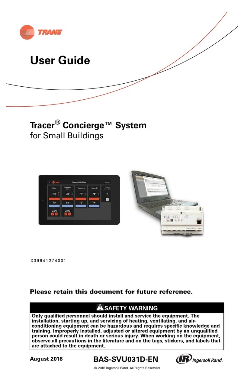
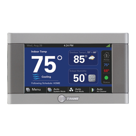
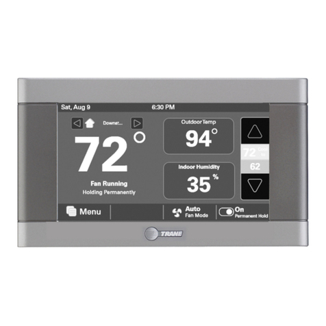
Trane Tracer Concierge User manual

SAFETY WARNING
Only qualified personnel should install and service the equipment. The installation,
starting up, and servicing of heating, ventilating, and air-conditioning equipment can
be hazardous and requires specific knowledge and training. Improperly installed,
adjusted or altered equipment by an unqualified person could result in death or
serious injury. When working on the equipment, observe all precautions in the
literature and on the tags, stickers, and labels that are attached to the equipment.
BAS-SVN208G-EN
August 2020
Order Numbers: X13760358001 Tracer 10-inch Display
Please retain this document for future reference.
Installation Instructions
Tracer Concierge™ System
Part 2 of 2: Setup for Small Buildings

©2020 Trane BAS-SVN208G-EN
Introduction
Read this manual thoroughly before operating or servicing this unit.
Warnings, Cautions, and Notices
Safety advisories appear throughout this manual as required. Your personal safety and
the proper operation of this machine depend upon the strict observance of these
precautions.
Important Environmental Concerns
Scientific research has shown that certain man-made chemicals can affect the earth’s
naturally occurring stratospheric ozone layer when released to the atmosphere. In
particular, several of the identified chemicals that may affect the ozone layer are
refrigerants that contain Chlorine, Fluorine and Carbon (CFCs) and those containing
Hydrogen, Chlorine, Fluorine and Carbon (HCFCs). Not all refrigerants containing these
compounds have the same potential impact to the environment. Trane advocates the
responsible handling of all refrigerants-including industry replacements for CFCs and
HCFCs such as saturated or unsaturated HFCs and HCFCs.
Important Responsible Refrigerant Practices
Trane believes that responsible refrigerant practices are important to the environment,
our customers, and the air conditioning industry. All technicians who handle
refrigerants must be certified according to local rules. For the USA, the Federal Clean Air
Act (Section 608) sets forth the requirements for handling, reclaiming, recovering and
recycling of certain refrigerants and the equipment that is used in these service
procedures. In addition, some states or municipalities may have additional
requirements that must also be adhered to for responsible management of refrigerants.
Know the applicable laws and follow them.
The three types of advisories are defined as follows:
WARNING Indicates a potentially hazardous situation which, if not avoided, could result
in death or serious injury.
CAUTION Indicates a potentially hazardous situation which, if not avoided, could result
in minor or moderate injury. It could also be used to alert against unsafe
practices.
NOTICE Indicates a situation that could result in equipment or property-damage only
accidents.
WARNING
Proper Field Wiring and Grounding Required!
Failure to follow code could result in death or serious injury. All field wiring MUST be
performed by qualified personnel. Improperly installed and grounded field wiring poses
FIRE and ELECTROCUTION hazards. To avoid these hazards, you MUST follow
requirements for field wiring installation and grounding as described in NEC and your
local/state electrical codes.

BAS-SVN208G-EN 3
Copyright
This document and the information in it are the property of Trane and may not be used
or reproduced in whole or in part, without the written permission of Trane. Trane
reserves the right to revise this publication at any time and to make changes to its
content without obligation to notify any person of such revision or change.
Trademarks
All trademarks referenced in this document are the trademarks of their respective
owners.
Revision History
• Updated the literature number from X39641273001F to BAS-SVN208*-EN.
• Updated the Order number in the Front Cover.
• Updated the Tracer SC to System Controller throughout the document.
• Updated the Change UC400 to XM Module in the Step 10.
• Updated the Special Recommendations for Single Zone RTU Installations section
in the Step 11.
• Updated the Tracer ES to Tracer Ensemble in the Step 17.
• Updated the potential causes for up or down arrow are disabled problem in the
Troubleshooting and Common Questions section.
WARNING
Personal Protective Equipment (PPE) Required!
Failure to wear proper PPE for the job being undertaken could result in death or serious
injury. Technicians, in order to protect themselves from potential electrical, mechanical,
and chemical hazards, MUST follow precautions in this manual and on the tags, stickers,
and labels, as well as the instructions below:
• Before installing/servicing this unit, technicians MUST put on all PPE recommended for
the work being undertaken. ALWAYS refer to appropriate MSDS sheets and OSHA
guidelines for proper PPE.
• When working with or around hazardous chemicals, ALWAYS refer to the appropriate
MSDS sheets and OSHA guidelines for information on allowable personal exposure
levels, proper respiratory protection, and handling recommendations.
• If there is a risk of arc or flash, technicians MUST put on all PPE in accordance with NFPA
70E or other country-specific requirements for arc flash protection, PRIOR to servicing
the unit.
WARNING
Follow EHS Policies!
Failure to follow instructions below could result in death or serious injury.
• All Trane personnel must follow the company’s Environmental, Health and Safety
(EHS) policies when performing work such as hot work, electrical, fall protection,
lockout/tagout, refrigerant handling, etc. Where local regulations are more
stringent than these policies, those regulations supersede these policies.
• Non-Trane personnel should always follow local regulations.

4 BAS-SVN208G-EN
Table of Contents
Installation Order . . . . . . . . . . . . . . . . . . . . . . . . . . . . . . . . . . . . . . . . . . . . . . . . 5
Step 9: Verify Package Contents . . . . . . . . . . . . . . . . . . . . . . . . . . . . . . . . . . . . 5
Step 10: Installation Checklist . . . . . . . . . . . . . . . . . . . . . . . . . . . . . . . . . . . . . . 5
Step 11: Air-Fi®Wireless Setup . . . . . . . . . . . . . . . . . . . . . . . . . . . . . . . . . . . . 6
Installation Locations . . . . . . . . . . . . . . . . . . . . . . . . . . . . . . . . . . . . . . . . . . 6
Typical Signal Range . . . . . . . . . . . . . . . . . . . . . . . . . . . . . . . . . . . . . . . . . . 6
Wireless Communicating Sensors (WCS) Height Requirements . . . . . . . 6
WCS Mounting Surfaces . . . . . . . . . . . . . . . . . . . . . . . . . . . . . . . . . . . . . . . 6
Air-Fi®Addressing . . . . . . . . . . . . . . . . . . . . . . . . . . . . . . . . . . . . . . . . . . . . 7
Establishing an Air-Fi®Network . . . . . . . . . . . . . . . . . . . . . . . . . . . . . . . . . 7
Automatic Network Formation and Sensor Association . . . . . . . . . . . . . . 7
WCS: Network Joining and Controller Association . . . . . . . . . . . . . . . . . . 8
Adding Additional WCIs to an Existing Network . . . . . . . . . . . . . . . . . . . . 8
Related Literature . . . . . . . . . . . . . . . . . . . . . . . . . . . . . . . . . . . . . . . . . . . . . 8
Step 12: Tracer UC210 Setup for Changeover Systems . . . . . . . . . . . . . . . . . 9
Step 13: System Controller Setup . . . . . . . . . . . . . . . . . . . . . . . . . . . . . . . . . . 10
Discover and Install Rooftop Units and VAV Boxes . . . . . . . . . . . . . . . . 10
Create a Tracer 10-inch Display User . . . . . . . . . . . . . . . . . . . . . . . . . . . . 10
Setup Areas (optional) . . . . . . . . . . . . . . . . . . . . . . . . . . . . . . . . . . . . . . . . 10
Coordinate Multiple HVAC Units with an Area . . . . . . . . . . . . . . . . . . . . 11
Lighting Only Control . . . . . . . . . . . . . . . . . . . . . . . . . . . . . . . . . . . . . . . . . 11
Lighting Controlled With HVAC . . . . . . . . . . . . . . . . . . . . . . . . . . . . . . . . . 12
Custom Graphics . . . . . . . . . . . . . . . . . . . . . . . . . . . . . . . . . . . . . . . . . . . . 15
Step 14: Mounting the Display . . . . . . . . . . . . . . . . . . . . . . . . . . . . . . . . . . . . 16
Step 15: Powering the Display . . . . . . . . . . . . . . . . . . . . . . . . . . . . . . . . . . . . 17
Step 16: Display Setup . . . . . . . . . . . . . . . . . . . . . . . . . . . . . . . . . . . . . . . . . . . 18
Configuring the Display . . . . . . . . . . . . . . . . . . . . . . . . . . . . . . . . . . . . . . . 18
Step 17: Project Commissioning Checklist . . . . . . . . . . . . . . . . . . . . . . . . . . . 21
Troubleshooting and Common Questions . . . . . . . . . . . . . . . . . . . . . . . . . . . 22
Troubleshooting Air-Fi®: WCI does not join network . . . . . . . . . . . . . . . 23

BAS-SVN208G-EN 5
Installation Order
Installation Order
• Hardware setup (Steps 1-8). See Tracer Concierge System Part 1 of 2: Hardware Setup
(BAS-SVN135*-EN).
• Setup System Controller and display (Steps 9-17, this document).
Step 9: Verify Package Contents
Note: Tracer Concierge 2.0 requires System Controller 4.0 as of December 2016.
Step 10: Installation Checklist
Verify that hardware installation is complete:
Verify the System Controller panel is attached to the wall and power is wired to it.
Verify XM Module I/O terminations are wired appropriately per the submittal.
Verify System Controller Air-Fi®Wireless is addressed properly and/or the Air-Fi
Wireless Network Best Practice guide BAS-SVX55. See also Step 11.
Verify that any rooftop units and VAV boxes with Air-Fi Wireless are addressed
properly per the submittal and/or the Air-Fi Wireless Network Best Practice Guide
BAS-SVX55.
Verify the Ethernet Cable for the customer’s network is connected to System Controller
Ethernet Port 1 (if applicable).
Follow this best practice for ReliaTel BCI for Constant Volume Rooftops: install a duct
temperature probe (part number 4190-7020) in the return air duct and wire the sensor
to the BCI-R's space temperature input. Unless the HVAC system is a Changeover
System, in which case place the duct temperature probe in the return air duct, before/
upstream of the bypass damper.
Table 1. Packaged contents
Item Quantity
10.1 in. Display 1
Display power cord 1
Installation Instructions 1
User Guide 1
USB-to-Ethernet Adapter 1
VESA Mounting Bracket 1
Ethernet Cable 1

6 BAS-SVN208G-EN
Step 11: Air-Fi®Wireless Setup
Installation Locations
To provide the best signal quality between wireless devices, mount WCIs and WCSs in
direct, unobstructed, line-of-sight paths. Where this is not possible, try to minimize the
number of barriers between a WCS and a WCI. In general, sheetrock walls and ceiling
tiles offer little restriction to the transmission of the radio signal throughout the building.
General guidelines are as follows:
• Locate wireless devices so that they are easily accessible and their covers can be
removed.
• Locate wireless devices in direct line of sight when possible.
• Avoid metal, concrete, and brick obstructions between wireless devices.
• Avoid placing devices inside metal enclosures.
• Locate wireless receivers in elevated space.
• Vertically mount wireless devices.
When selecting a WCS location, avoid the following:
• Areas of direct sunlight
• Areas in the direct airstream of air diffusers
• Exterior walls and other walls that have a temperature differential between the two
sides
• Areas that are close to heat sources such as sunlight, appliances, concealed pipes,
chimneys, or other heat-generating equipment
• Drafty areas
• Dead spots behind doors, projections screens, or corners
• Walls that are subject to high vibration
• Areas with high humidity
• High traffic areas (to reduce accidental damage or tampering)
• Placing the sensor inside metal enclosures
Typical Signal Range
The WCI has a typical signal range (radius) of 200 ft—potentially more for line-of-sight
installations, less for obstructed installations. The exception is for WCIs mounted inside
the return plenum of a rooftop unit (RTUs), which have a range limited to 100 ft.
Special Recommendations for Single Zone RTU Installations
In RTU/VAV systems, there is adequate network density, which minimizes the need for
repeaters. The recommended mounting location for RTU installations is in the return
plenum, above the roof penetration. This location provides the best overall sensor and
communication link quality.
Trane has special recommendations for coordinator and repeater placement on sites
without VAV boxes. We recommend relocating the WCI below the roof deck in a
serviceable location on these applications.
Wireless Communicating Sensors (WCS) Height
Requirements
The recommended maximum mounting height is 54 inches from the bottom of the back
plate to the floor. If a parallel approach by a person in a wheelchair is required, reduce
the maximum height to 48 inches.
WCS Mounting Surfaces
Using the hardware provided, mount the back plate of the sensor to a flat surface such
as sheetrock or plaster, or ton an electrical junction box. The sensor must be mounted
plumb for accurate temperature control and to ensure proper air movement through the

BAS-SVN208G-EN 7
Step 11: Air-Fi®Wireless Setup
sensor.
• If mounting onto sheetrock or plaster, use the plastic threaded anchors (pre-drilling
holes is not usually necessary) and the two M3.5 x 20 mm mounting screws.
• For mounting onto an electrical junction box, use the two 6-32 x 3/4 in. screws.
Air-Fi®Addressing
Air-Fi addressing of WCS and WCI determines which devices can communicate on an
Air-Fi network. GRP and NET must be set the same for all WCS and WCI on the
Air-Fi network. WCS address is configured on the sensor’s display. WCS Address
must match the appropriate unit controller rotary address setting. See Air-Fi
WCS Configuration Instructions X3964126601 or Air-Fi WCS Quick Reference Guide
BAS-SVU029*-EN for more information.
Figure 1. Air-Fi addressing example: WCIs and WCSs
Establishing an Air-Fi®Network
When all aspects of hardware installation are complete, you are ready to power up the
system and establish the wireless network.
Best Practice: Power up all devices in the network at the same time. If you are
unable to do this, power them up in the following order:
1. All WCIs.
2. All unit controllers: UC210, UC400, UC600, BCI-I, BCI-R.
3. The System Controller.
4. WCSs, if present.
Note: If the coordinator WCI is powered up 1 hour or more before the other devices on
the network, then you must open the network manually or with Tracer TU.
Automatic Network Formation and Sensor Association
A WCI that is connected to a System Controller is auto-assigned as the network
coordinator. The coordinator WCI allows all WCIs and WCSs having matching addresses
to automatically join the network. (For more details about the process of network
establishment, see the Air-Fi®Wireless System IOM (BAS-SVX40).
After the network is formed, WCSs automatically associate with their designated
controllers.
UC/BCI
System
Controller
UC/BCI
WCI WCI
GRP NET
NET
GRP NET
111
11
WCI
12
GRP
1
Sn: 1
UC: 101
Network 1
101 102
Sn: 1
UC: 102
gn: 11 gn: 11
Group and
network
addresses
must match.
UC/BCI
addresses
must
match.
WCS WCS
1
2
3
4
5
6
7
8
9
0
NET
GRP
1
2
3
4
5
6
7
8
9
0
WCI addressing

8 BAS-SVN208G-EN
Step 11: Air-Fi®Wireless Setup
Note: The network must be open for a WCS to join the network, but does not need to
be open for the WCS to be manually assigned to a controller.
WCS: Network Joining and Controller Association
After addresses are set, the WCS will immediately attempt to join the network and
associate with the controller.
• Error code E2 will appear on the sensor display until the WCS successfully joins the
network. Until network joining is successful, the WCS will repeat its attempt to join
every 60 minutes.
• Association between the WCS and the controller will automatically be initiated. The
WCS will repeat its attempt to associate every 15 minutes until successful. Error
code E1 will be displayed until association is successful.
• You can press the center button twice at any time to cause the WCS to re-attempt
to join the network and to associate with the WCI.
Adding Additional WCIs to an Existing Network
1. Press the OPEN_NET button on the System Controller WCI to open the network for
joining for one hour. Every member WCI will indicate that the network is open. Any
WCI with a correct rotary address setting that is located within radio range of a
network member, will join the network.
Note: Pressing the OPEN_NET button on a member WCI will open only that one WCI.
2. Observe the green NWK LED illuminate on a WCI that joins the network.
Related Literature
• BAS-SVX40: Air-Fi®Wireless System Installation, Operation, and Maintenance:
Describes how to address, install, modify, and troubleshoot an Air-Fi®Wireless
system.
• X39641264001: Air-Fi®Wireless Communications Interface (WCI) Installation
Instructions: A quick-start guide to addressing and installing a WCI.
• X39641265001: Air-Fi®Wireless Communications Sensor (WCS) Installation
Instructions: A quick-start guide to addressing and installing a WCS.
• X39641266001: Air-Fi®Wireless Communications Sensor (WCS) Configuration
Instructions: A quick-start guide to configuring a WCS.

BAS-SVN208G-EN 9
Step 12: Tracer UC210 Setup for Changeover Systems
Step 12: Tracer UC210 Setup for Changeover
Systems
Best Practice: Install a duct temperature probe (part number 4190-7020) in the return
air duct, before/upstream of the bypass damper. This temperature is used in the
changeover application of System Controller to control the VAS AHU member. Wire the
sensor to the rooftop's space temperature input.
Note: It is important that the sensor be located upstream of the bypass, so that it reflects
the air temperature from the zones and is unaffected by the bypassed airflow.
With Tracer TU, setup Tracer UC210s for use with dampers without flow sensing:
1. Change the box type to generic.
2. Set the box size to 100 CFM.
3. Adjust setpoints to percent value.
4. Disconnect transducer from UC module (no flow ring).
5. Put binary value, index #13, “Diagram Flow Sensor Failure” out of service, normal.
6. Change analog value, index #52 “PD Mode Min Air Valve Position” from 40% to 10%
(or whatever the desired minimum cool flow is).
7. Setup Bypass Damper UC210 with correct actuator type binary value #2, “Actuator
Type.” Select Modulating Triac (default) or Modulating Linear.
Figure 2. Actuator type

10 BAS-SVN208G-EN
Step 13: System Controller Setup
This section describes how to set up your System Controller to interact with the Tracer
10-inch Display. System Controller should be setup by Trane personnel.
Note: See System Controller Installation and Setup BAS-SVX31 for further details on
setting up System Controller.
Setup the System Controller as you would typically. Ensure that you do the following:
Name the System Controller suitably, as the name appears on the display.
Set Units of measure
Set the IP Address (optional)
Set the Date/Time
Enable wireless communication
Discover and Install Rooftop Units and VAV Boxes
Discover and install rooftop units and VAV boxes. Tracer Concierge is designed for Trane
controls. Non-Trane or non-standard unit controls may not have their setpoint properly
controlled by Tracer Concierge. See Technical Support for more details.
Create a Tracer 10-inch Display User
Create a new System Controller user for Tracer Concierge. Tracer 10-inch Display will use
these credentials to authenticate with System Controller. Below is an example System
Controller user. You may choose to set your own user name and password rather than
use the example.
User name: LocalDisplay
Password: Tr4cer#
First Name: Local
Last Name: Display
Role: Tracer Concierge or Tracer Concierge without Schedules. In most cases, choose
the “Tracer Concierge” role. If you do not want Schedules to appear on the display,
choose “Tracer Concierge without Schedules” role.
Note: If the system will include a VAV system (VAV, changeover, or changeover bypass)
and therefore a VAS, then set the user preference for default priority level to 11 or 8. This
allows the display user to override the individual VAV boxes to occupied.
Figure 3. Override priority
Setup Areas (optional)
Tracer 10-inch Display shows spaces and areas. Areas are optional, and can be used to

BAS-SVN208G-EN 11
Step 13: System Controller Setup
coordinate lights with HVAC or multiple HVAC units together. Areas can also be used to
show lighting BOPs on the display.
Name areas suitably, as area names are shown on the Tracer Display main screen.
Note: Spaces and area names will that are longer than 12 characters will wrap on the
main screen.
Coordinate Multiple HVAC Units with an Area
To coordinate or share setpoints among multiple HVAC units, do the following with area
control:
When adding the HVAC member, check that the space will participate in calculations.
This is required to calculate the average Space Temperature (even if there is only one
RTU in the area) to be shown on the display.
Figure 4. Configure area members
Important: For every space that is a member of an Area, create Global Referencers
to send setpoints from area (as adjusted on the display) to its members. This ensures
that the points are synchronized between the space and area, so the user sees the
setpoints accurately on the display. For example, the offset must be the same for the
display to show the actual setpoint for the space.
Figure 5. Global referencers
Table 2. Global referencers
Lighting Only Control
To control lights from the main screen, setup an area with Lighting member types.
Source (Area) Destination (RTU)
Space Temperature Setpoint Space Temperature Setpoint BAS
Occupied Offset Occupied Offset
Standby Offset Occupied Standby Offset
Unoccupied Heating Setpoint Unoccupied Heating Setpoint
Unoccupied Cooling Setpoint Unoccupied Cooling Setpoint

12 BAS-SVN208G-EN
Step 13: System Controller Setup
Figure 6. Assign lighting member types
After creating an area for only lighting members:
1. Click the Configuration tab.
2. Set Unoccupied Heating and Cooling to Disable.
Figure 7. Unoccupied operations
Important: This will prevent the area from turning on the lights during unoccupied
heating and cooling.
When an area has only lighting members, the Tracer Display main screen shows a light
bulb and override button. No up/down arrows are shown. See the “Parking Lot Lights”
example in Figure 8.
Figure 8. Lighting only area
Lighting Controlled With HVAC
When lighting is to be controlled with HVAC, include lighting BOPs as Lighting member
types with the RTU in the area. When an area has a lighting member, a light bulb icon
appears on the Tracer Display main screen for that area. See the “Office” example in
Figure 9.

BAS-SVN208G-EN 13
Step 13: System Controller Setup
Figure 9. HVAC-only area and HVAC lighting area
Changeover Systems
Create a Variable Air system
1. Click the Enable Changeover checkbox.
2. Select either Variable Air System or Constant Volume Air System.
3. Enable the optional Optimization functions and click Next.
Figure 10. Create VAS
Note: Duct Static Optimization is not supported for Constant Volume systems.
4. Select the Air Handler, VAV boxes, and Ventilation members. Ensure that you do not
have the Constant Volume AHU in an area.
5. Check the appropriate boxes for tagging and priority heat. See System Controller
online help for more information.

14 BAS-SVN208G-EN
Step 13: System Controller Setup
Figure 11. Create VAS
6. Under Functions, define the number of normal and strong opposite callers required
for the system to changeover. Define the minimum changeover time or use the
default.
7. Choose the device controlling the bypass damper, such as the UC210 with Bypass
Damper Control programming.
Note: To set the bypass configuration, an Air Handler member must be defined.
8. Set the Discharge Temperature limits and deadbands.
9. If the Air Handler does not have a Discharge Air Temperature (DAT) sensor, do the
following:
• For the VAVs, provide a source temperature from elsewhere in the system.
Reference a value from elsewhere in the system to the source temperature of the
VAV members.
Figure 12. VAS setup - Source temperature reference
• For the Air Handler, manually set the DAT of the Air Handler to a reasonable value,
even if the point is out of service Note that the Discharge Air Temperature (DAT) of
the Air Handler has an effect on the VAS system based on the DAT High and Low
Limit definition. Using Reliatel controls as an example, when there is no DAT sensor,
the BCI-R will set the value for DAT to “65,535” and put the point out of service.When
the point is out of service, it's no longer “in fault” and therefore VAS uses the value
for the sequence. Because 65,535 is greater than the DAT High Limit, VAS puts the
unit in Fan Only mode. To avoid this issue when there is no DAT sensor, leave the
DAT point out of service and set it to a value within the limit range so that the system
will operate correctly.
Schedules
• Tracer Concierge only supports System Controller schedules that are type: HVAC
and Binary. Analog and multi-state schedules will not appear on the Tracer 10-inch
Display.
• Schedule names will appear on the Tracer 10-inch Display, so name schedules
suitably.Best practices for schedule names:
•Name schedules with 24 characters or less.
•End the name with the word Schedule. For example, Store Schedule or Parking
Lot Lights Schedule.
Note: Schedule names longer than 24 characters will wrap and then end in ellipsis for
longer names.
• Schedule members should be areas, such as lighting and/or HVAC areas or spaces
such as constant volume rooftop units.

BAS-SVN208G-EN 15
Step 13: System Controller Setup
Custom Graphics
All graphics for Tracer Concierge must be custom graphics. Tracer Concierge will not
show standard or template graphics.
Order Custom Graphics from Centralized Graphics. On the Graphics Order Sheet, check
the Tracer Concierge box, so the graphics are suitable for Tracer 10-inch Display.
Graphics should be 1280x720 resolution.
• Graphic names will appear on the Tracer 10-inch Display, so name graphics suitably.
• Name graphics with 24 characters or less. There is not a fixed limit on name length,
but longer names will not display well in Tracer Concierge.
• Give graphics descriptive names. For example, First Floor Temps.
• Add property references, such as:
•Temperatures
•Flood Fill for floorplans
•Setpoints. As a best practice, use the new setpoint widget that looks like the main
screen.
•Overrides. As a best practice, use the new override widget that looks like the
main screen.
• System Controller graphic navigation buttons are not supported in Tracer
Concierge. Instead, use target or link.
Best practices for custom graphics
• Limit or do not use navigation between custom graphics. Each graphic will appear
in the menu.
• No external links to the web.
• No links to stock System Controller web pages, such as Building Summary, Status
screens, Alarms, Schedules, and Data Logs. These links will be disabled on the
Tracer 10-inch Display screen.
• Use the new setpoint and override widgets.
• Avoid elements better suited for the System Controller web interface: binary toggle,
list box, setpoint box, override buttons, and navigation buttons.
Figure 13. Setpoint and override widgets
• Check the point references by using Utilities | Resolve Graphic to ensure there are
not template point references.
•Verify the points are referenced properly.
•Verify all points have a specific Object Name and that none are left with Default
as the Object Name. Except for navigation objects, which may be left at default.
Important: Any graphic that has a point with Default as the Object Name will not be
shown on the display.

16 BAS-SVN208G-EN
Step 14: Mounting the Display
Figure 14. Resolve graphic
• Alternatively, in the graphic HTML file, check that the template flag is set to false. If
it is set to true, return to the Resolve Graphic utility.
Step 14: Mounting the Display
Note: The Display is designed for conditioned indoor environments only.
Note: The display can be connected to System Controller:
•Directly by Ethernet cable
•By the optional Wi-Fi router
•On the customer network with the System Controller
Important: If using the Trane Wi-Fi router, the Tracer 10-inch Display must be powered
up after the System Controller and router to ensure the router uses the correct default
addresses for System Controller and the display. Alternatively, the display may be
hardwired to the System Controller.
The Display mounts to the wall using a VESA mount. The required VESA mounting
bracket size is 75 mm x 75 mm. A VESA mount (Order Number X05010511010) is available
as an accessory from Trane, but any standard VESA mount should be acceptable. Brand,
tilt, swivel and any other features are acceptable.
1. Select the wall space to mount the display. Mounting constraints are as follows:
• The display must be powered continuously so mount it near an electrical outlet.
• The display communicates to the System Controller using either Wi-Fi or Ethernet
cable connection. Use standard Wi-Fi guidelines to select the display location.
• The display should be accessible for any users that are allowed to make
adjustments using the Display.
2. Disassemble the VESA mount.
3. Install the wall section onto the wall.
4. Install the display section of the VESA mount onto the Display enclosure using the
4 screws included with the VESA mount.
5. Re-assemble the VESA mount so the Display is now on the wall.

BAS-SVN208G-EN 17
Step 15: Powering the Display
1. Connect the Ethernet cable from System Controller Port 2 to the Tracer 10-inch
Display USB Port 1. Or alternatively for a Wi-Fi connection, connect the Ethernet cable
from System Controller Port 2 to the Wi-Fi router Port 1.
2. Plug in the display power adapter to an appropriate wall outlet.
3. If the display does not power up, then press the power switch on the back of the
display.
Figure 15. Back of the display
Note: The actual locations of power button and ports may vary.
Power
button

18 BAS-SVN208G-EN
Step 16: Display Setup
This section describes how to setup your Tracer 10-inch Display. This should be
performed by Trane personnel.
Important: If using the Trane Wi-Fi router, the Tracer 10-inch Display must be powered
up after the System Controller and router to ensure the router uses the correct default
addresses for System Controller and the display. Alternatively, the display may be
hardwired to the System Controller.
Configuring the Display
1. Select the Connection tab.
Figure 16. Connection tab
2. Tap Device Settings.
3. If connecting to System Controller via the wireless network:
a. Choose Wi-Fi and wait for the display to refresh available Wi-Fi networks.
b. If using the Wi-Fi router from Trane, select ciscosb1 and verify security is WPA2
PSK.
c. Enter the Wi-Fi password: Simple#Retail.
d. Verify that the display is connected to ciscosb.
Note: If there are problems connecting, forget the network and start over.
4. If connecting to System Controller directly via an Ethernet cable:
a. Choose More | Ethernet.
b. Select Use static IP and set the following:
•IP Address: 192.168.2.11 Note: This address will work when the display is
connected to System Controller Port 2, which defaults to 192.168.2.10.
•Gateway: 192.168.2.10 (System Controller Port 2 address)
•Netmask: 255.255.255.0
•DNS 1: 192.168.2.10 (System Controller Port 2 address)
•DNS 2: (blank)

BAS-SVN208G-EN 19
Step 16: Display Setup
Note: Wi-Fi must be disabled to use a wired Ethernet connection between the Tracer 10-
inch Display and System Controller.
5. To exit the Device Settings screen, use the Back button located on th back of the
display near the power button to return to the Connections tab.
6. Enter the IP Address of System Controller. It defaults to System Controller Port 2.
7. Enter the User Name and Password of the System Controller user you previously
setup. Hostname may be used in place of the IP address. However, it must be a fully
qualified hostname.
8. Click Connect.
Note: Do not add a port in the IP address field. Tracer Concierge will attempt a secure
connection (via https) first. If not available, it will establish a standard connection (http).
9. Select the Zones tab.
Figure 17. Zones tab
10.Set the zone order by dragging areas and spaces into selected positions. To hide a
zone from the display, drag it to the bottom row.If an area is controlling the space
setpoint via a global referencer, place the area in the upper row and the space in the
bottom row to hide it.
11.Select the Options tab.
12.If desired, enable Admin PIN Support. Admin PIN requires users to enter the Admin
PIN to view or modify System Controller connection settings, Zone configuration,
display options, and contact information.
13.PIN support prevents non-authorized users (new employees or the general public)
from changing a setting on the Tracer 10-inch Display.

20 BAS-SVN208G-EN
Step 16: Display Setup
Figure 18. Options tab
14.Setpoint limit defaults to +/-3 degrees. From the Options tab, you can change the
setpoint limit from 1-9 or disable it entirely.
Note: This setpoint limit applies to the setpoints on the main screen and will not apply
to any custom graphics.
15.Select the Contact tab, enter contact information for the person who supports Tracer
Concierge system.
Figure 19. Contact tab
Other manuals for Tracer Concierge
1
Table of contents
Other Trane Control System manuals

Trane
Trane CVRD User manual

Trane
Trane Tracer Summit Mounting instructions

Trane
Trane Tracer CH530 User manual

Trane
Trane ComfortLink II XL 850 User manual

Trane
Trane LCD Control Series Quick start guide

Trane
Trane Tracer TD7 User manual

Trane
Trane CCUN 205-211 User manual

Trane
Trane BAYCC24VK01A Assembly instructions

Trane
Trane ComfortLink II XL 1040 Operation manual

Trane
Trane Tracer Concierge BMTC015ABC012000 User manual