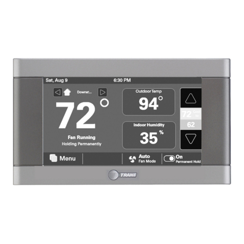
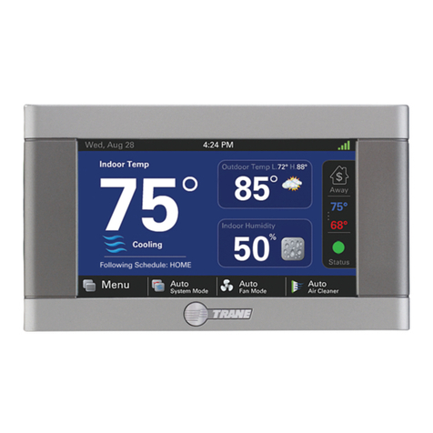
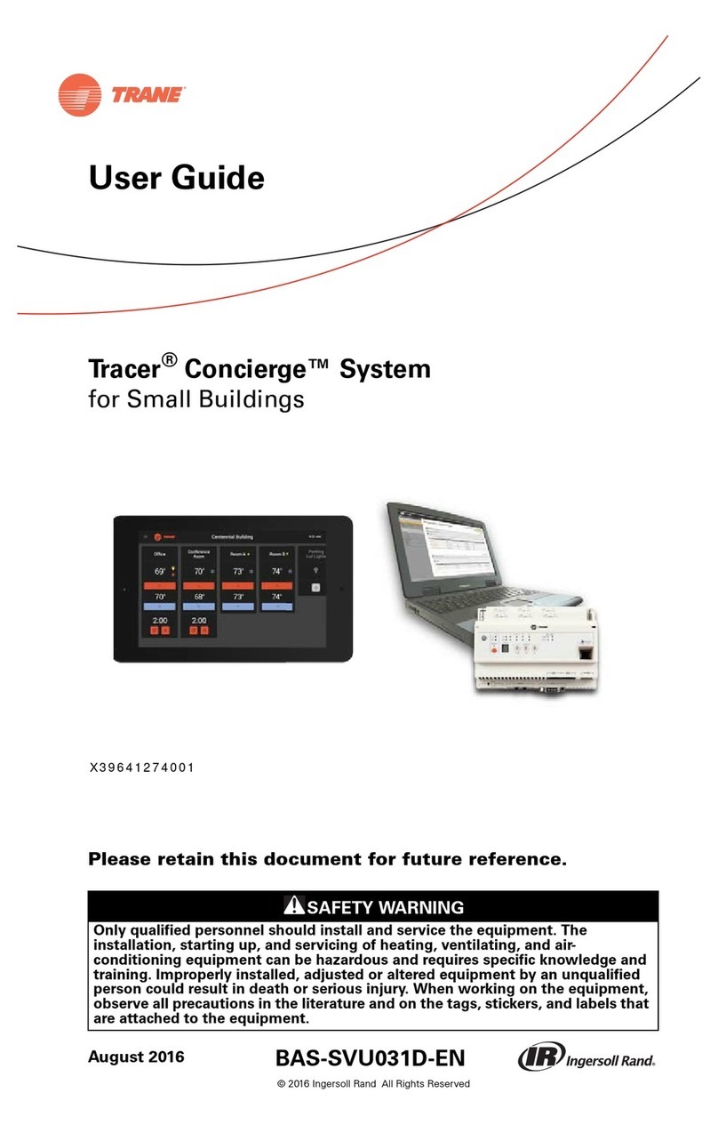
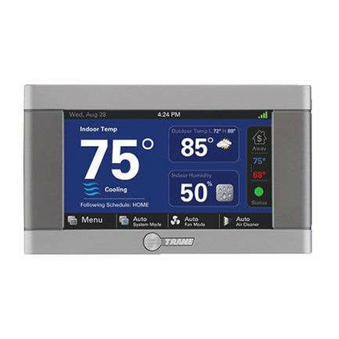
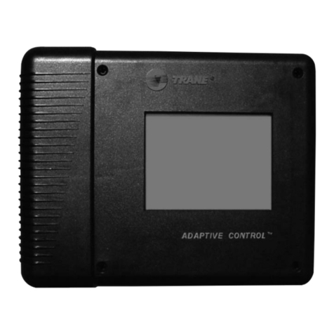
Trane Tracer Concierge BMTC015ABC012000 User manual

Tracer® Concierge™ System
Installation Instructions
May 2020 BAS-SVN040B-EN
Model Numbers: BMTC015ABC012000, BMTC015CAC012000
BMTC030ABC012000, BMTC045CBC012000
BMTC015CBC012000, BMTC060CBC012000
BMTC030CBC012000, BMTC030CAC012000
SAFETY WARNING
Only qualified personnel should install and service the equipment. The installation, starting up, and servicing of
heating, ventilating, and air-conditioning equipment can be hazardous and requires specific knowledge and training.
Improperly installed, adjusted or altered equipment by an unqualified person could result in death or serious injury.
When working on the equipment, observe all precautions in the literature and on the tags, stickers, and labels that are
attached to the equipment.

©2020 Trane BAS-SVN040B-EN
Introduction
Warnings, Cautions, and Notices
Safety advisories appear throughout this manual as required. Your personal safety and the proper
operation of this machine depend upon the strict observance of these precautions.
The three types of advisories are defined as follows:
WARNING Indicates a potentially hazardous situation which, if not avoided, could result in
death or serious injury.
CAUTIONsIndicates a potentially hazardous situation which, if not avoided, could result in
minor or moderate injury. It could also be used to alert against unsafe practices.
NOTICE Indicates a situation that could result in equipment or property-damage only
accidents.
Important Environmental Concerns
Scientific research has shown that certain man-made chemicals can affect the earth’s naturally
occurring stratospheric ozone layer when released to the atmosphere. In particular, several of the
identified chemicals that may affect the ozone layer are refrigerants that contain Chlorine, Fluorine
and Carbon (CFCs) and those containing Hydrogen, Chlorine, Fluorine and Carbon (HCFCs). Not all
refrigerants containing these compounds have the same potential impact to the environment.
Trane advocates the responsible handling of all refrigerants-including industry replacements for
CFCs and HCFCs such as saturated or unsaturated HFCs and HCFCs.
Important Responsible Refrigerant Practices
Trane believes that responsible refrigerant practices are important to the environment, our
customers, and the air conditioning industry. All technicians who handle refrigerants must be
certified according to local rules. For the USA, the Federal Clean Air Act (Section 608) sets forth the
requirements for handling, reclaiming, recovering and recycling of certain refrigerants and the
equipment that is used in these service procedures. In addition, some states or municipalities may
have additional requirements that must also be adhered to for responsible management of
refrigerants. Know the applicable laws and follow them.
WARNING
Proper Field Wiring and Grounding Required!
Failure to follow code could result in death or serious injury. All field wiring MUST be
performed by qualified personnel. Improperly installed and grounded field wiring poses FIRE
and ELECTROCUTION hazards. To avoid these hazards, you MUST follow requirements for field
wiring installation and grounding as described in NEC and your local/state electrical codes.
Failure to follow code could result in death or serious injury.

WARNING
Personal Protective Equipment (PPE) Required!
Failure to wear proper PPE for the job being undertaken could result in death or serious injury.
Technicians, in order to protect themselves from potential electrical, mechanical, and chemical
hazards, MUST follow precautions in this manual and on the tags, stickers, and labels, as well
as the instructions below:
• Before installing/servicing this unit, technicians MUST put on all PPE required for the work
being undertaken (Examples; cut resistant gloves/sleeves, butyl gloves, safety glasses, hard
hat/bump cap, fall protection, electrical PPE and arc flash clothing). ALWAYS refer to
appropriate Safety Data Sheets (SDS) and OSHA guidelines for proper PPE.
• When working with or around hazardous chemicals, ALWAYS refer to the appropriate SDS
and OSHA/GHS (Global Harmonized System of Classification and Labeling of Chemicals)
guidelines for information on allowable personal exposure levels, proper respiratory
protection and handling instructions.
• If there is a risk of energized electrical contact, arc, or flash, technicians MUST put on all PPE
in accordance with OSHA, NFPA 70E, or other country-specific requirements for arc flash
protection, PRIOR to servicing the unit. NEVER PERFORM ANY SWITCHING,
DISCONNECTING, OR VOLTAGE TESTING WITHOUT PROPER ELECTRICAL PPE AND ARC
FLASH CLOTHING. ENSURE ELECTRICAL METERS AND EQUIPMENT ARE PROPERLY RATED
FOR INTENDED VOLTAGE.
WARNING
Follow EHS Policies!
Failure to follow instructions below could result in death or serious injury.
• All Trane personnel must follow the company’s Environmental, Health and Safety (EHS)
policies when performing work such as hot work, electrical, fall protection, lockout/tagout,
refrigerant handling, etc. Where local regulations are more stringent than these policies,
those regulations supersede these policies.
• Non-Trane personnel should always follow local regulations.
Introduction
BAS-SVN040B-EN 3
Copyright
This document and the information in it are the property of Trane, and may not be used or
reproduced in whole or in part without written permission. Trane reserves the right to revise this
publication at any time, and to make changes to its content without obligation to notify any person
of such revision or change.
Trademarks
All trademarks referenced in this document are the trademarks of their respective owners.
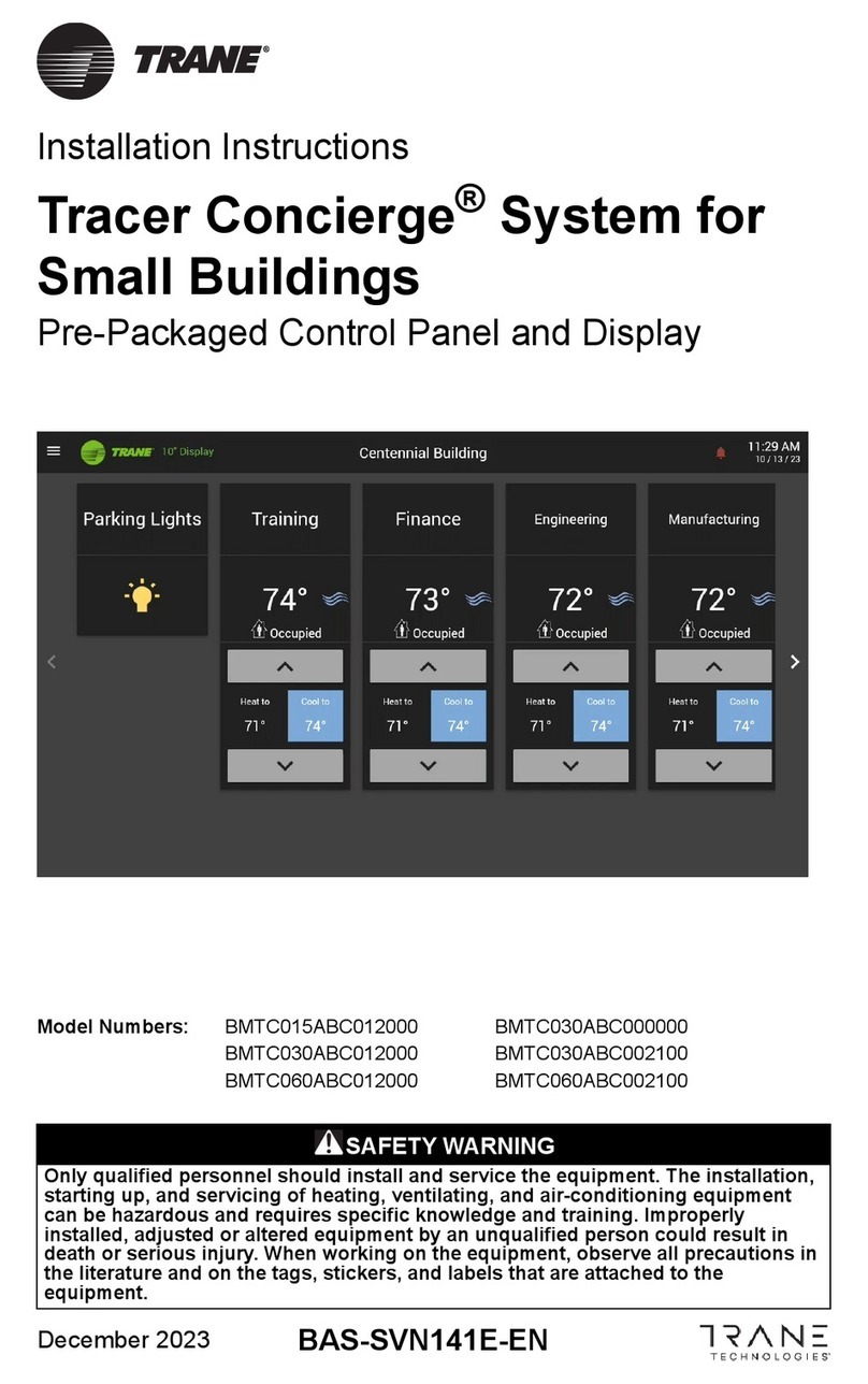

Table of Contents
4BAS-SVN040B-EN
Installation . . . . . . . . . . . . . . . . . . . . . . . . . . . . . . . . . . . . . . . . . . . . . . . . . . . . . . . 5
Step 1: Verify Package Content . . . . . . . . . . . . . . . . . . . . . . . . . . . . . . . . . . . . 5
Step 2: Install BCI-R and Air-Fi® Wireless (Optional) . . . . . . . . . . . . . . . . . . . 6
Step 3: Install the UC400 2H/2C and Air-Fi® Wireless for Non-Trane RTUs 7
Step 4: Install the UC210 Bypass Damper and Air-Fi® Wireless . . . . . . . . . . 8
Step 5: Install Tracer Concierge Panel . . . . . . . . . . . . . . . . . . . . . . . . . . . . . . 10
Dimensions and Clearances . . . . . . . . . . . . . . . . . . . . . . . . . . . . . . . . . . . . 10
Location and Mounting Guidelines . . . . . . . . . . . . . . . . . . . . . . . . . . . . . . 12
Install Enclosure Door . . . . . . . . . . . . . . . . . . . . . . . . . . . . . . . . . . . . . . . . . 14
Step 6: Wire I/O . . . . . . . . . . . . . . . . . . . . . . . . . . . . . . . . . . . . . . . . . . . . . . . . 16
Step 7: Mount the Display . . . . . . . . . . . . . . . . . . . . . . . . . . . . . . . . . . . . . . . 16
Step 8: System Startup . . . . . . . . . . . . . . . . . . . . . . . . . . . . . . . . . . . . . . . . . . 17
Step 9: Display Setup . . . . . . . . . . . . . . . . . . . . . . . . . . . . . . . . . . . . . . . . . . . 18
Step 10: Installing the Wi-Fi Router . . . . . . . . . . . . . . . . . . . . . . . . . . . . . . . . 19
Step 11: Project Commissioning Checklist . . . . . . . . . . . . . . . . . . . . . . . . . . 19
Agency Listing and Compliance . . . . . . . . . . . . . . . . . . . . . . . . . . . . . . . . . . 20

BAS-SVN040B-EN 5
Installation
Step 1: Verify Package Content
Table 1. Packaged contents
Part Number Package Contents
BMTC015ABC012000 Concierge Controller with 15 device license, Air-Fi® Wireless Communication Interface
(WCI), mounting kit (4 anchors/4 screws)
BMTC030ABC012000 Concierge Controller with 30 device license, Air-Fi® Wireless Communication Interface
(WCI), mounting kit (4 anchors/4 screws)
BMTC015CBC012000 Concierge Controller with 15 device license, XM30 Module, XM32 Module, Air-Fi® Wireless
Communication Interface (WCI), enclosure with mounting kit (4 anchors/4 screws)
BMTC030CBC012000 Concierge Controller with 30 device license, XM30 Module, XM32 Module, Air-Fi® Wireless
Communication Interface (WCI), enclosure with mounting kit (4 anchors/4 screws)
BMTC045CBC012000 Concierge Controller with 45 device license, XM30 Module, XM32 Module, Air-Fi® Wireless
Communication Interface (WCI), enclosure with mounting kit (4 anchors/4 screws)
BMTC060CBC012000 Concierge Controller with 60 device license, XM30 Module, XM32 Module, Air-Fi® Wireless
Communication Interface (WCI), enclosure with mounting kit (4 anchors/4 screws)
BMTC015CAC012000 Concierge Controller with 15 device license, XM30 Module, XM32 Module, Air-Fi® Wireless
Communication Interface (WCI), LON Module, enclosure with mounting kit
(4 anchors/4 screws)
BMTC030CAC012000 Concierge Controller with 30 device license, XM30 Module, XM32 Module, Air-Fi® Wireless
Communication Interface (WCI), LON Module, enclosure with mounting kit
(4 anchors/4 screws)
Before proceeding with installing the Tracer Concierge Panel, set up the unit controllers as
required, such as BCI-R and Air-Fi® Wireless (Step 2), UC400 and Air-Fi® Wireless (Step 3), and
UC210 and Air-Fi® Wireless (Step 4).

6BAS-SVN040B-EN
Installation
Step 2: Install BCI-R and Air-Fi® Wireless (Optional)
If required for this site, install the BCI-R and Air-Fi® Wireless. Use the wiring harness provided with
the BCI-R to wire from the RTRM(J-4, 5-pin connector) to BCI-R(J-1, 4-pin connector).For more
information see Installation guide BACnet™ Communication Interface for ReliaTel™ Controllers
(BCI-R) For use with Voyager,™ Odyssey,™ and Precedent™ rooftop units Ordering Number:
KIT15864 (RF-SVN03A-EN). Set the BCI-R and WCI rotary address switch appropriately per the
submittal.
Important: Before plugging in the Air-Fi® card, power down the rooftop controller, per
instructions in the installation instructions RF-SVN03A-EN. Then power the
controller and Air-Fi® card together.
Install the Air-Fi® Wireless Interface, per the instructions, with the wire harness provided. When
using the Air-Fi® with the BCI-R, set the BCI-R link switch as shown in the following figure. See
Integration Guide BACnet Communications Interface for ReliaTel Controllers (BCI-R) (BAS-
SVO09D-EN) for more information.
Figure 1. BCI-R and Air-Fi® wireless interface
Note: Ensure Air-Fi® Wireless and zone sensors are addressed per the submittal.

BAS-SVN040B-EN 7
Installation
Step 3: Install the UC400 2H/2C and Air-Fi® Wireless for Non-Trane
RTUs
If required for this site, install the UC400 2H/2C and Air-Fi® Wireless on non-Trane equipment. For
more information, see Tracer UC400 Pre-programmed for RTU or Heat Pump (X39641251-01B). The
point list below is for your convenience.
Table 2. Tracer® UC400 2H/2C RTU controller inputs and outputs
Inputs and Outputs Label Functions Descriptions
Analog Inputs
AI1 Space Temperature Sensor 10kΩThermistor
AI2 Space Temperature Setpoint 1kΩInput
AI3 --
AI4 Discharge Air Temperature Sensor 10kΩThermistor
AI5 Outdoor Air Temperature Sensor 10kΩThermistor
P1 -- --
P2 -- --
Universal Inputs UI1 -- --
UI2 Occupancy Input (Binary) Open = Occupied, Closed = Unoccupied
Binary Inputs
BI1 Condensate Overflow Input Open = Normal, Closed = Alarm
BI2 Heat Pump Selection Input Open = DX, Closed = Heat Pump
BI3 Supply Fan Status Open = Off, Closed = On
BI4 -- --
BI5 -- --
Analog Outputs AO1 -- --
AO2 -- --
Binary Outputs
Relays
BO1 Supply Fan Start Stop Command --
BO2 -- --
BO3 -- --
24VAC Triacs
BO4 Compressor 1 Command --
BO5 Compressor 2 Command --
BO6 Heat Stage W1 Command --
BO7 Heat Stage W2 Command --
BO8 Reversing Valve Command Off = Cooling, On = Heating
BO9 Auxiliary Heat Command --
Note: Ensure Air-Fi® Wireless and zone sensors are addressed per the submittal.

8BAS-SVN040B-EN
Installation
Step 4: Install the UC210 Bypass Damper and Air-Fi® Wireless
If required for this site, install the UC210 Bypass Damper. See the installation documentation. The point list
below is for your convenience.
Table 3. I/O points
Location Function
Pressure Input Duct Static Pressure Local
AI3/DAT Discharge Air Temperature (Optional)
Actuator Damper Actuator
Note: Ensure Air-Fi® Wireless and zone sensors are addressed per the submittal.
Addressing of the Wireless Communication Sensors (WCS) and Wireless Communication Interface
(WCI) determines which devices can communicate on an Air-Fi® network. On all WCS and WCI, the
GRP and NET are set at 1and 1. When installing, confirm that these remain at 1 and 1.
Figure 2. Air-Fi® addressing
On unit controllers, such as rooftop units, VAV boxes, and bypass dampers, set the rotary address
settings to unique numbers. Set the first to 002, and so on. It's helpful to be sequential and not to
skip numbers; however, skipping numbers will not cause problems. Duplicate numbers will cause
communication problems.

Figure 3. Unit controller rotary addressing
BAS-SVN040B-EN 9
Installation
On WCS zone sensors, set:
• GRP and NET to 1 and 1
• Address the WCS to match the corresponding unit controller
To enter the WCS address settings, press and hold the address button for 3 seconds.
Figure 4. Press the address button
For more information, see Air-Fi® Wireless Communication Sensor (WCS) Configuration
Instructions, X3964126001 that is shipped with each zone sensor.

10 BAS-SVN040B-EN
Installation
Step 5: Install Tracer Concierge Panel
Important: Do not power the display until instructed to do so in Installation Instructions.
Dimensions and Clearances
Figure 6, p. 11 shows the internal enclosure dimensions and minimum clearances. Select a
mounting location that provides adequate space for the minimum clearance dimensions. Refer to
Figure 7, p. 11 for external enclosure dimensions.
Figure 5. Internal view
Outlets are provided for Tracer Concierge
accessories including cellular router,
wifi router and the concierge display Convenience
outlet for a
laptop
Optional XM32:
Outdoor Air
Temperature
Input Module
Optional XM30:
output module for
lighting/exhaust fan
control
Optional module
for LonTalk
Communication
Concierge
Controller
Mounting holes
Mounting
holes
Mounting hole
Note: The mounting holes may be
covered if the enclosure includes
factoryinstalled devices.

Figure 6. Enclosure minimum clearances with cover
Figure 7. External dimensions
BAS-SVN040B-EN 11
Installation
1
2 in
.
(
305 mm
)
1
2 in.
(
305 mm
)
50 in.
(
1270 mm
)
Rec
o
mmen
d
e
d
12 in.
(
305 mm
)
24 in
.
(
610 mm
)
36 in
.
(
914 mm
)
15 in
(381 mm)
K
nockouts for 1 inch
(
25 mm
)
and .75 inch
(
19 mm
)
condui
t
Knockout for .50 inch
(
13 mm
)
conduit (for AC wiring
)
2.25 in
(
56 mm
)
14.75
in
(
373 mm
)
Knockout for .75 in
(
19 mm
)
condui
t
Knockout for 50 i
n
(
13 mm
)
condui
t
3.125 in
(
80 mm
)
16
.
5
i
n
)
)
)
m
m
(
418 m
m
m
m
)
5
.
5
i
n
(
140 mm
)
13.25 in
(
337 mm
)

12 BAS-SVN040B-EN
Installation
Location and Mounting Guidelines
Location
The location should meet the following operating environment requirements and clearances:
Table 4. Operating environment specifications
Temperature: From 32°F to 122°F (0°C to 50°C)
Humidity: 5–95% non-condensing
Power Requirements: 120 Vac: 9A maximum, 1 phase, 60 Hz
Weight: Mounting surface must be able to support 60 lb. (28 kg)
Dimensions: 16 ½ in. × 14 ¾ in. × 5 ½ in. (418 mm × 373 mm × 140 mm)
Installation: U.L. 840: Category 3
Pollution: U.L. 840: Degree 2
Important: The Tracer Concierge Panel enclosure must be installed indoors.
Trane recommends locating the enclosure:
• Where service personnel have easy access.
• In areas that restrict public access to minimize tampering or vandalism.
Mounting Instructions
Note: The internal enclosure panel comes with four (4) mounting holes (refer to the locations in
Figure 5, p. 10).
1. Using the enclosure as a template, mark the location of the four (4) mounting holes on the
mounting surface to accommodate the supplied #10 screws and/or #10 wall anchors.
2. Set aside the enclosure and drill the marked location holes for the screws.
Note: Use wall anchors if the mounting surface is dry wall or masonry.
3. Secure the enclosure to the mounting surface with the enclosed #10
screws and #10 wall anchors.
4. Remove the tie wraps that secure the modules to the DIN rail during shipping.
Wiring High Voltage AC Power
Read all WARNINGS, CAUTIONS, and NOTICES prior to wiring high-voltage AC power.
WARNING
Hazardous Voltage!
Failure to disconnect power before servicing could result in death or serious injury.Disconnect
all electric power, including remote disconnects before servicing. Follow proper lockout/tagout
procedures to ensure the power can not be inadvertently energized. Verify that no power is
present with a voltmeter.
WARNING
Proper Field Wiring and Grounding Required!
Failure to follow code could result in death or serious injury. All field wiring MUST be
performed by qualified personnel. Improperly installed and grounded field wiring poses FIRE
and ELECTROCUTION hazards. To avoid these hazards, you MUST follow requirements for field
wiring installation and grounding as described in NEC and your local/state/national electrical
codes.

NOTICE
Use Copper Conductors Only!
Failure to use copper conductors could result in equipment damage as the equipment was not
designed or qualified to accept other types of conductors.
BAS-SVN040B-EN 13
Installation
To ensure proper operation of the controllers, install the power supply circuit in accordance with
the following guidelines:
• The panel must receive power from a dedicated power circuit. Failure to comply could cause
panel malfunctions.
• A disconnect switch for the dedicated power circuit must be near the panel, within easy reach
of the operator, and marked as the disconnecting device for the panel.
• Do not run input or output wires in the same conduit or wire bundle with high voltage wire or
24 Vac wiring. Failure to comply could cause the controller to malfunction due to electrical
noise.
• Power wiring must comply with the National Electrical Code™ (NEC) and applicable electrical
codes.
• 120 Vac wiring requires three-wire service (Line, Neutral, Ground). Refer to Panel 10 for terminal
locations.
Note: The transformer voltage utilization range is 98–132 Vac (120 Vac nominal).
1. Lock open the supply-power disconnect switch.
2. At the top-right corner of the enclosure, remove the knockout for 0.50 inch (13 mm) conduit.
3. Open or remove the enclosure door if it is already installed.
4. Inside of the enclosure at the top-right corner, remove the line voltage area cover plate.
5. Feed the 120 Vac power wire into the enclosure.
6. Using Figure 8, p. 14, connect the line wire to the ‘L’ terminal.
7. Connect the neutral wire to the ‘N’ terminal.
8. Connect the green ground wire to the chassis ground screw.
Note: The ground wire should be continuous back to the circuit breaker panel.
WARNING
Hazardous Voltage!
Failure to follow instructions below could result in death or serious injury. Alwaysmake sure to
put the cover plate back in place before operating the controller.
9. Replace the cover plate.
10. On a field-supplied label, record the location of the circuit breaker panel and the electrical
circuit. Attach the label to the cover plate.

Figure 8. AC wiring
14 BAS-SVN040B-EN
Installation
Install Enclosure Door
1. Unpack the door and check for any missing or damaged parts.
2. Position the door at a 90 degree angle from the enclosure, as shown below.

Figure 9. Installing the enclosure door
BAS-SVN040B-EN 15
Installation
3. Align the hinge pegs on the door with the hinge holes on the enclosure and gently lower the
door until it rests securely in the hinge holes.
4. Verify that the door swings freely on the hinges and that the magnetic latches hold the door
securely when it is closed.

16 BAS-SVN040B-EN
Installation
Step 6: Wire I/O
The field I/O wiring is specific for each application.
Module Rotary Dial Terminals Name Notes
XM30 01 UI/AO 1 Outside Air
Temperature Thermistor
XM30 01 UI/AO 2 N/A Not used
XM30 01 UI/AO 3 N/A Not used
XM30 01 UI/AO 4 N/A Not used
XM32 02 BO1 XM32 Binary Output 1 Must be wired as dry contact; used for lighting
output or other (for example, exhaust fan)
XM32 02 BO2 XM32 Binary Output 2 Must be wired as dry contact; used for lighting
output or other (for example, exhaust fan)
XM32 02 BO3 XM32 Binary Output 3 Must be wired as dry contact; used for lighting
output or other (for example, exhaust fan)
XM32 02 BO4 XM32 Binary Output 4 Must be wired as dry contact; used for lighting
output or other (for example, exhaust fan)
Step 7: Mount the Display
Note: The display is designed for conditioned indoor environments only. Mount the display where
occupants can access it for comfort/setpoint control and minor schedule modifications.
The display mounts to the wall using a VESA mount. The required VESA mounting bracket size is
75 mm x 75 mm. A VESA mount is included with the display, but any standard VESA mount should
be acceptable. Brand, tilt, swivel and any other features are acceptable.
1. Select the wall space to mount the display. Mounting constraints are as follows:
•The display must be powered continuously, so mount it near an electrical outlet or near the
enclosure with the accessory outlet.
•The display communicates to the Concierge Controller using either Wi-Fi or Ethernet cable
connection. Use standard Wi-Fi guidelines to select the display location.
•The display should be accessible for any users that are allowed to make adjustments using
the display.
2. Disassemble the VESA mount.
3. Install the wall section onto the wall.
4. Install the display section of the VESA mount onto the display enclosure using the four (4)
screws included with the VESA mount.
5. Re-assemble the VESA mount so the display is now on the wall.
6. For ease of initial setup, connect an Ethernet cable between the display and Concierge
Controller’s Ethernet Port 2. Later, set up a Wi-Fi router or put both the display and Concierge
Controller on the customer’s network.
7. If mounted near the enclosure, plug the display into the accessory outlet in the enclosure.

Figure 10. Back of display with ethernet and power connector
BAS-SVN040B-EN 17
Installation
Step 8: System Startup
Important: Ensure all equipment and Air-Fi® Wireless are powered and operating before
proceeding. This is because the network will be formed on power up of Tracer
Concierge Controller.
1. Apply power to the panel. Close the supply power disconnect switch that was locked open when
connecting the 120 VAC Power Wires.
2. Press the power button on the Concierge Controller. Watch the controller go through its LED
sequence ending with dancing dashes.
Note: The network automatically stays open 1 hour. After each Air-Fi® Wireless module joins, the
1 hour timer starts over. If time expires, press the OPEN NET button on the Air-Fi® Wireless
module to re-open the network.
Figure 11. Power button
Note: For more details or troubleshooting information, see the
•Tracer Concierge Installation, Operation, and Maintenance Guide (BAS-SVX074).
•Wireless Comm Installation, Operation, and Maintenance (BAS-SVX40).
Power button

18 BAS-SVN040B-EN
Installation
3. Connect the Ethernet cable for customer’s network to Ethernet Port 1.
Step 9: Display Setup
1. Power on the display by pressing the power button on the back of the display.
2. Follow the steps in the Setup Wizard. See the Tracer Concierge Installation, Operation, and
Maintenance Guide (BAS-SVX074) for details.
Figure 12. Setup wizard

BAS-SVN040B-EN 19
Installation
Step 10: Installing the Wi-Fi Router
Note: The Concierge Controller in its pre-wired enclosure should be operating and
communicating to all the equipment before installing the Wi-Fi router.
The optional Wi-Fi router is used when the Concierge Controller and the Concierge Display cannot
both be on the customer's Wi-Fi network.The router (Order Number: X13651632010) is set up to
allow the Concierge Controller and the Display to communicate on their own small (2 device) Wi-
Fi network.
1. Install the router near the pre-wired enclosure containing the Concierge Controller.
2. Plug router into the accessory outlet in the enclosure.
NOTICE
Avoid damage to the contents of the pre-wired enclosure when opening a knockout for the
Ethernet cable.
3. Connect the Ethernet cable included with the router to the router on one end and into Concierge
Controller's Port 2 on the other. See the following figure.
Figure 13. Concierge controller ethernet ports detail
4. Connect power to the Wi-Fi router. The pre-wired enclosure containing the Concierge
Controller also contains a convenience outlet.
Step 11: Project Commissioning Checklist
Verify that hardware installation is complete:
Verify the Concierge Controller panel is attached to the wall and power is wired to it.
Verify Concierge Controller Air-Fi® Wireless is addressed properly per the submittal and/or the
Air-Fi® Wireless Network Best Practice guide BAS-SVX55C-EN.
Verify the Ethernet Cable for the customer’s network is connected to Concierge Controller
Ethernet Port 1 (if applicable).
Verify that any rooftop units with Air-Fi® Wireless are connected and addressed properly per the
submittal and/or the Air-Fi® Wireless Network Best Practice guide BAS-SVX55C-EN.

20 BAS-SVN040B-EN
Installation
Agency Listing and Compliance
United States Compliance
(Enclosure and modules are UL Listed separately)
UL Listed — UL 916 Energy Management Accessory
Canadian Compliance
(Enclosure and modules are CUL Listed separately)
CUL Listed — CSA C22.2 No. 205
Other manuals for Tracer Concierge BMTC015ABC012000
2
This manual suits for next models
7
Table of contents
Other Trane Control System manuals

Trane
Trane BAYCC24VK01A Assembly instructions

Trane
Trane CCUN 205-211 User manual

Trane
Trane Tracer Concierge User manual

Trane
Trane ComfortLink II XL 850 User manual

Trane
Trane Tracer Concierge User manual

Trane
Trane LCD Control Series Quick start guide

Trane
Trane Tracer TD7 User manual

Trane
Trane Tracer Summit Mounting instructions

Trane
Trane XL824 User manual

Trane
Trane Tracer Concierge BMTC015ABC012000 User manual