SAFETY WARNING
Only qualified personnel should install and service the equipment. The installation,
starting up, and servicing of heating, ventilating, and air-conditioning equipment can
be hazardous and requires specific knowledge and training. Improperly installed,
adjusted or altered equipment by an unqualified person could result in death or
serious injury. When working on the equipment, observe all precautions in the
literature and on the tags, stickers, and labels that are attached to the equipment.
132
4 5 6 7
©2021
Installation Instructions
0 - 50% Motorized Outside Air Damper
Foundation™ Packaged Rooftop Units
15 to 25 Tons
Model Number: Used With:
BAYDMPR300* E/GBC180-300
Warnings, Cautions, and Notices
Read this manual thoroughly before operating or servicing this unit. Safety
advisories appear throughout this manual as required. Your personal safety
and the proper operation of this machine depend upon the strict observance
of these precautions.
The three types of advisories are defined as follows:
WARNING Indicates a potentially hazardous situation which,
if not avoided, could result in death or serious
injury.
CAUTION Indicates a potentially hazardous situation which,
if not avoided, could result in minor or moderate
injury. It could also be used to alert against unsafe
NOTICE Indicates a situation that could result in
equipment or property-damage only accidents.
Important Environmental Concerns
Scientific research has shown that certain man-made chemicals can affect
the earth’s naturally occurring stratospheric ozone layer when released to
the atmosphere. In particular, several of the identified chemicals that may
affect the ozone layer are refrigerants that contain Chlorine, Fluorine and
Carbon (CFCs) and those containing Hydrogen, Chlorine, Fluorine and
Carbon (HCFCs). Not all refrigerants containing these compounds have the
same potential impact to the environment. Trane advocates the responsible
handling of all refrigerants-including industry replacements for CFCs such
as HCFCs and HFCs.
Important Responsible Refrigerant Practices
Trane believes that responsible refrigerant practices are important to the
environment, our customers, and the air conditioning industry. All
technicians who handle refrigerants must be certified according to local
rules. For the USA, the Federal Clean Air Act (Section 608) sets forth the
requirements for handling, reclaiming, recovering and recycling of certain
refrigerants and the equipment that is used in these service procedures. In
addition, some states or municipalities may have additional requirements
that must also be adhered to for responsible management of refrigerants.
Know the applicable laws and follow them.
WARNING
Proper Field Wiring and Grounding Required!
Failure to follow code could result in death or serious injury. All field wiring
MUST be performed by qualified personnel. Improperly installed and grounded
field wiring poses FIRE and ELECTROCUTION hazards. To avoid these hazards,
you MUST follow requirements for field wiring installation and grounding as
described in NEC and your local/state electrical codes.
WARNING
Personal Protective Equipment (PPE) Required!
Failure to wear proper PPE for the job being undertaken could result in death or
serious injury. Technicians, in order to protect themselves from potential
electrical, mechanical, and chemical hazards, MUST follow precautions in this
manual and on the tags, stickers, and labels, as well as the instructions below:
• Before installing/servicing this unit, technicians MUST put on all PPE
required for the work being undertaken (Examples; cut resistant
gloves/sleeves, butyl gloves, safety glasses, hard hat/bump cap, fall
protection, electrical PPE and arc flash clothing). ALWAYS refer to
appropriate Safety Data Sheets (SDS) and OSHA guidelines for proper PPE.
• When working with or around hazardous chemicals, ALWAYS refer to the
appropriate SDS and OSHA/GHS (Global Harmonized System of
Classification and Labeling of Chemicals) guidelines for information on
allowable personal exposure levels, proper respiratory protection and
handling instructions.
If there is a risk of energized electrical contact, arc, or flash, technicians MUST
put on all PPE in accordance with OSHA, NFPA 70E, or other country-specific
requirements for arc flash protection, PRIOR to servicing the unit. NEVER
PERFORM ANY SWITCHING, DISCONNECTING, OR VOLTAGE TESTING
WITHOUT PROPER ELECTRICAL PPE AND ARC FLASH CLOTHING. ENSURE
ELECTRICAL METERS AND EQUIPMENT ARE PROPERLY RATED FOR
INTENDED VOLTAGE.
WARNING
Follow EHS Policies!
Failure to follow instructions below could result in death or serious injury.
• All Trane personnel must follow the company’s Environmental, Health and
Safety (EHS) policies when performing work such as hot work, electrical, fall
protection, lockout/tagout, refrigerant handling, etc. Where local
regulations are more stringent than these policies, those regulations
supersede these policies.
• Non-Trane personnel should always follow local regulations.
Copyright
This document and the information in it are the property of Trane, and may
not be used or reproduced in whole or in part without written permission.
Trane reserves the right to revise this publication at any time, and to make
changes to its content without obligation to notify any person of such
revision or change.
Trademarks
All trademarks referenced in this document are the trademarks of their
respective owners.
Model Number Description
All products are identified by a multiple-character model number that
precisely identifies a particular type of unit. Its use will enable the
owner/operator, installing contractors, and service engineers to define the
operation, specific components, and other options for any specific unit.
When ordering replacement parts or requesting service, be sure to refer to
the specific model number and serial number printed on the unit
nameplate.
Introduction
This instruction covers installation of the motorized damper on E/GA*180-
300 units.
Parts List
1 - Motorized OA Damper Assembly
10 - Screws
1 - Blockoff; Bottom
Installation
Field Installed Damper
1. Uncrate the damper and locate all parts shown in Figure 1.
Figure 1. Damper contents
1
2
WARNING
Hazardous Voltage w/Capacitors!
Failure to disconnect power and discharge capacitors before servicing could
result in death or serious injury.
Disconnect all electric power, including remote disconnects and discharge all
motor start/run capacitors before servicing. Follow proper lockout/ tagout
procedures to ensure the power cannot be inadvertently energized. Verify with
a CAT III or IV voltmeter rated per NFPA 70E that all capacitors have discharged.
2. Remove unit end panel, retain the screws for later use.
Figure 2. Remove end panel
3. Attach block off 2 to unit by using four screws.
Figure 3. Install block off
4. Secure economizer assembly 1 to unit using ten screws.
Figure 4. Install economizer assembly
1
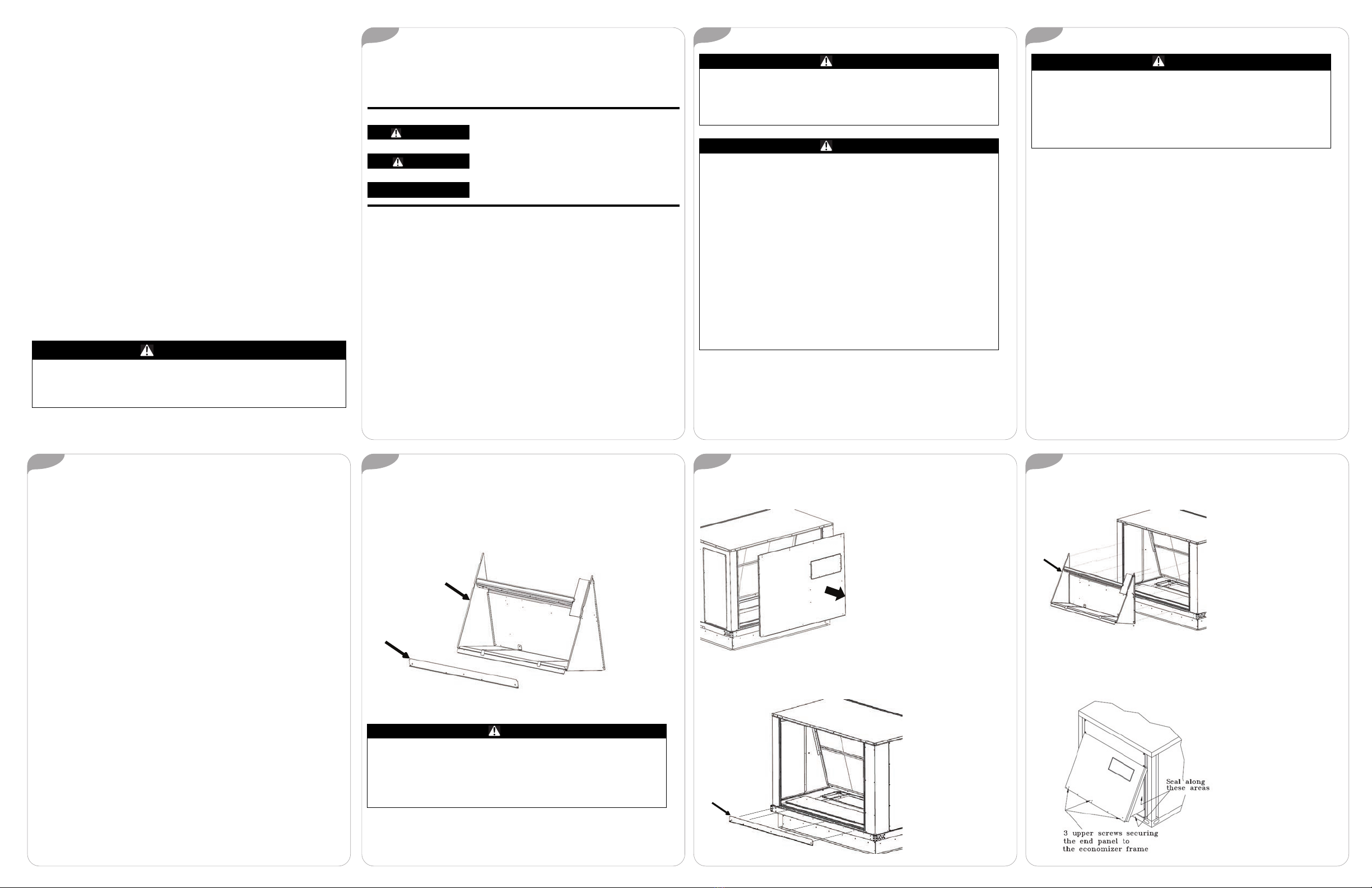
5. Attach end panel back to unit using the screws removed in Step 2 and
seal indicated areas in Figure 5, p. 1 with field supplied silicone sealant.
Figure 5. Reinstall end panel
September 2021 ACC-SVN154D-EN


