VAV-SVN04A-EN
©2002 American Standard, Inc. All rights reserved
These instructions do not cover all
variations in systems nor provide for
every possible contingency that may
arise at a jobsite installation.
INSPECTION:
Check carefully for any shipping
damage.This must be reported to and
claims made against the transportation
company immediately. Any missing
parts should be reported to your
supplier at once and replaced with
authorized parts only.
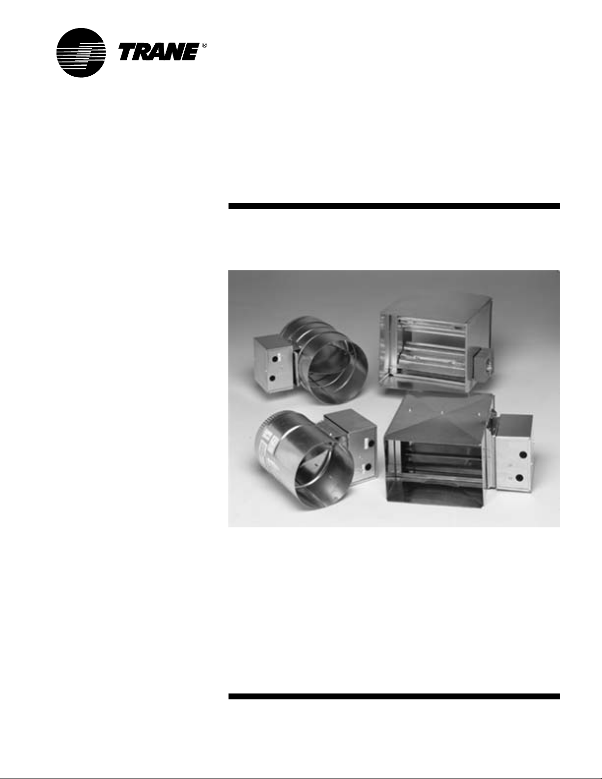
DAMPER DESCRIPTIONS
Round Dampers
Cylinder 18-gage galvanized–rolled
and seam welded
Damper 22-gage galvanized steel
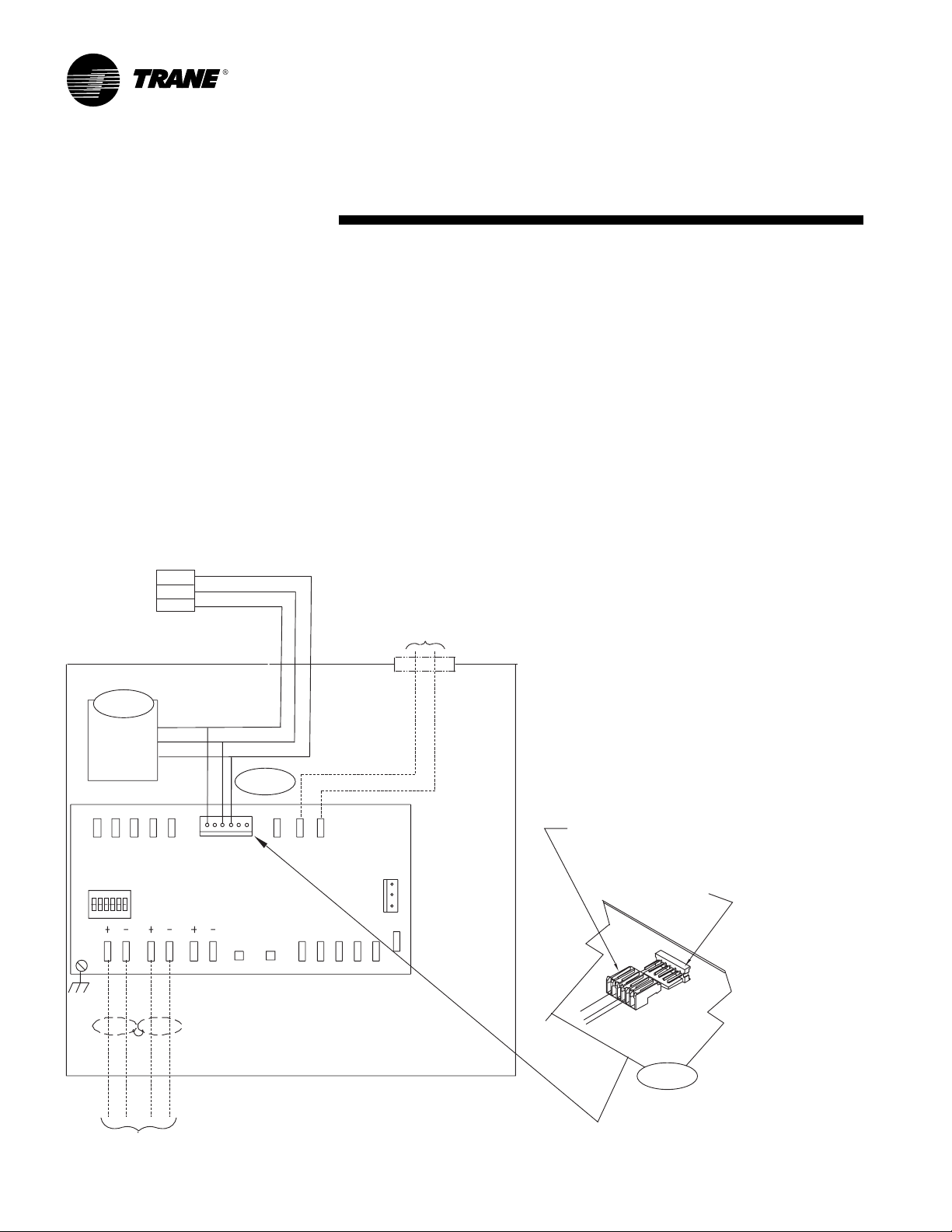
Actuator Internal actuator w/
synchronous motor and
gear reduction is direct
coupled to the damper
shaft. It has a drive time of
57 seconds. Microswitches
stop the drive motor at the
full-open and full-closed
positions.
··
··
·Electrical Rating:
Power Supply—24 VAC (20
to 30 VAC) at 50/60 Hz
Transformer Sizing—2.0 VA
maximum at nominal
voltage, Class 2
Round Bypass Dampers
Size Shipping
Diameter (in.) Length (in.) Weight
6 12 11 lbs
8 12 12 lbs
10 16 17 lbs
12 16 18 lbs
Round Zone Dampers
Size Shipping
Diameter (in.) Length (in.) Weight
6 12 11 lbs
8 12 12 lbs
10 16 17 lbs
12 16 18 lbs
14 20 27 lbs
16 20 31 lbs
Rectangular Bypass Damper
Sheet metal box 24-gage galvanized
steel
Length 16"
Damper frame 13-gage galvanized
steel
Damper blades 16-gage galvanized
steel
Blade pin 3/8"
Rectangular Bypass Dampers
Size No. of Shipping
W" x H" Blades Weight
14 x 12 2 16 lbs
16 x 16 3 21 lbs
20 x 20 3 29 lbs
30 x 20 3 40 lbs
Rectangular Zone Damper
Sheet metal box 24-gage galvanized
steel
Length 16"
Damper frame 18-gage galvanized
steel
Damper blades 18-gage galvanized
steel
Gears ABS plastic
Blade pin 3/8"
Rectangular Zone Dampers
Size No. of Shipping
H" x W" Blades Weight
08 x 12 2 8 lbs
08 x 14 2 10 lbs
08 x 16 2 12 lbs
10 x 16 3 14 lbs
10 x 20 3 16 lbs
14 x 18 4 18 lbs
Rectangular Actuator
Specification:
··
··
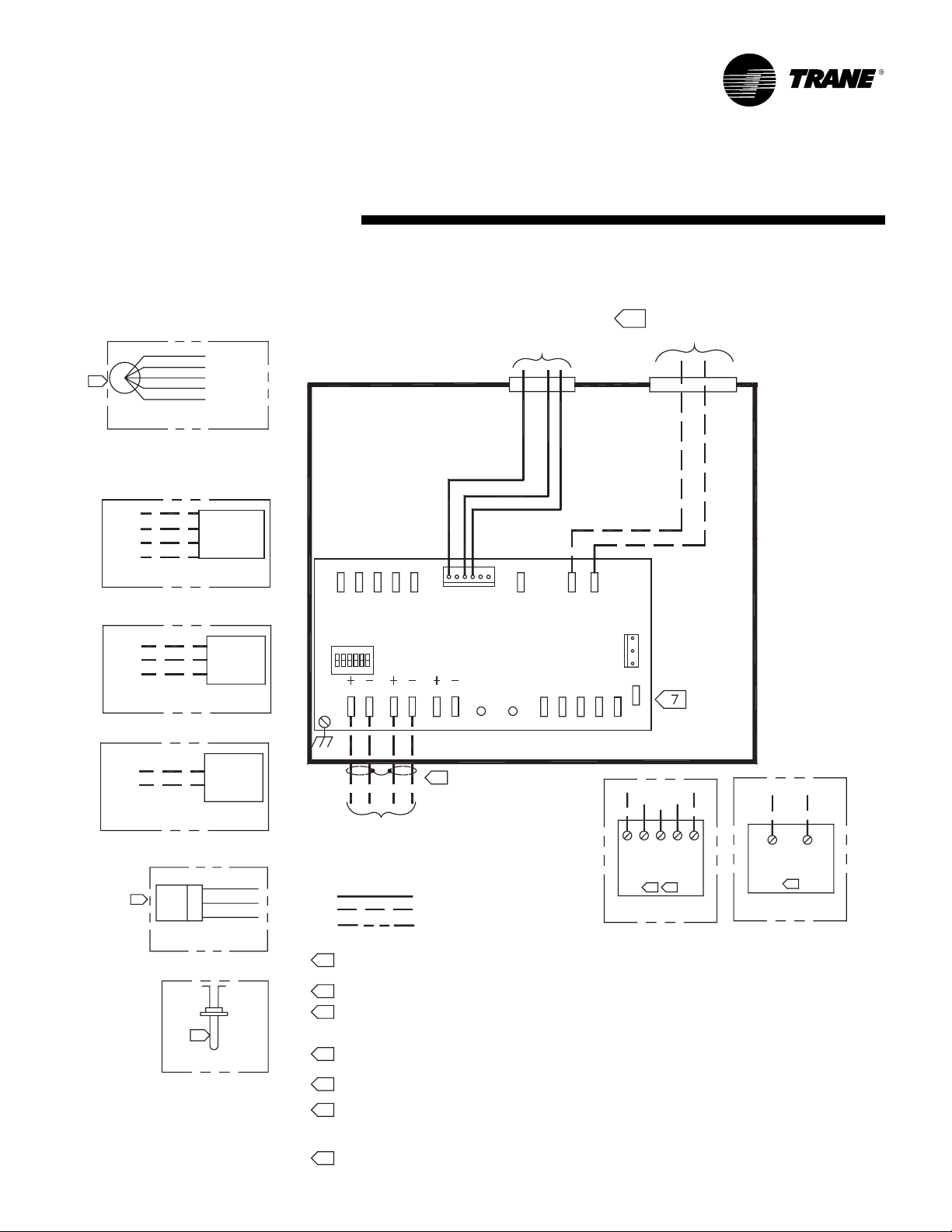
·Actuator Design:
3 Wire 18 ga 24 VAC Floating Point
Control, Non-spring return
··
··
·Actuator Housing:
HousingType—NEMA 1, IP20
··
··
·Rotation Range:
Adjustable from 30°–90°, clockwise or
counterclockwise
··
··
·Electrical Rating:
Power Supply—24 VAC (20 to 30 VAC)
at 50/60 Hz
Transformer Sizing—2.5 VA maximum
at nominal voltage, Class 2
··
··
·Manual Override:
External release lever
··
··
·Humidity:
90% RH maximum, non-condensing
··
··
·Temperature Rating:
Ambient – 35°–125°F (2°–52°C)
Shipping and Storage: -20°–150°F
(-29°–66°C)
··
··
·To r qu e :
Running: 35 lb-in (4 N-m)
Breakaway: 35 lb-in (4 N-m) minimum
Stall: 40 lb-in (4.5 N-m)
minimum
··
··
·RunningTime for 90° Rotation:
60 seconds at 60 Hz nominal
72 seconds at 50 Hz nominal
··
··
·Weight:
1.5 lb (0.68 kg)
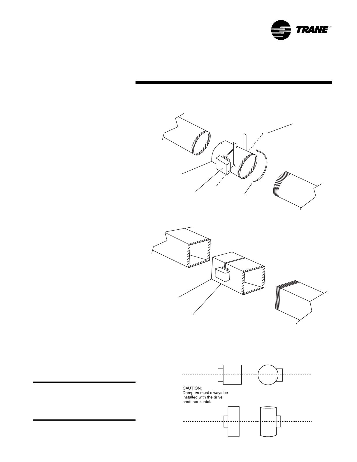
General