To Install Thermostat
NOTICE: Thermostat installation must conform to local and national building and electrical codes and
ordinances.
NOTICE: Mount the thermostat about ve feet above the oor. Do not mount the thermostat on an
outside wall, in direct sunlight, behind a door, or in an area affected by a vent or duct.
1. Turn off power by removing the fuse or switching the appropriate circuit breaker off.
2. To remove cover, remove screw and pull gently at the seam at the top.
3. Set thermostat away from working area.
4. Align thermostat base with junction box mounting holes and feed the control wires through hole.
5. Use supplied screws to mount thermostat base to junction box.
NOTICE: Be sure exposed portion of wires does not touch other wires.
6. Connect wiring harness.
7. Snap thermostat to base that is mounted on the wall. Refasten with screw.
8. Turn on power to the system at the main service panel.
9. Test thermostat operation as described in “Testing the Thermostat”.
2 or 4 Pipe
Fan Coil Thermostat, 3 Speed
Auto Changeover
18-30 VAC
Hardwired
3518-7065
• 2-pipe systems
• 4-pipe systems
• Pipe sensor compatible
•Congurable
•Largedisplaywithbacklight
•SelectableFahrenheitorCelsius
•Relayoutputs(minimumvoltagedropin
thermostat)
• Remote sensor compatible
Warnings, Cautions, and Notices
Read this manual thoroughly before operating or servicing this unit. Safety advisories
appear throughout this manual as required. Your personal safety and the proper operation
of this machine depend upon the strict observance of these precautions.
• This thermostat is for 18-30 VAC applications only; do not use on voltages over 30 VAC
• Use this thermostat only as described in this manual
Installation Guide
ACC-SVN224B-EN
©2020 TRANE
AUGUST 2020
Onlyqualiedpersonnelshouldinstallandservicetheequipment.Theinstallation,starting
up,andservicingofheating,ventilating,andair-conditioningequipmentcanbehazardous
andrequiresspecicknowledgeandtraining.Improperlyinstalled,adjustedoraltered
equipmentbyanunqualiedpersoncouldresultindeathorseriousinjury.Whenworkin9
ontheequipment,observeallprecautionsintheliteratureandonthetags,stickers,and
labelsthatareattachedtotheequipment.
SAFETY WARNING
The two types of advisories are dened as follows:
WARNING Indicates a potentially hazardous situation which, if not
avoided, could result in death or serious injury.
Indicates a situation that could result in equipment or
property-damage only accidents.
NOTICE
Important Environmental Concerns
Scientic research has shown that certain man-made chemicals can affect the earth’s
naturally occurring stratospheric ozone layer when released to the atmosphere. In
particular, several of the identied chemicals that may affect the ozone layer are
refrigerants that contain Chlorine, Fluorine and Carbon (CFCs) and those containing
Hydrogen, Chlorine, Fluorine and Carbon (HCFCs). Not all refrigerants containing these
compounds have the same potential impact to the environment. Trane advocates the
responsible handling of all refrigerants-including industry replacements for CFCs such as
HCFCs and HFCs.
Important Responsible Refrigerant Practices
Trane believes that responsible refrigerant practices are important to the environment, our
customers, and the air conditioning industry. All technicians who handle refrigerants must
be certied according to local rules. For the USA, the Federal Clean Air Act (Section 608)
sets forth the requirements for handling, reclaiming, recovering and recycling of certain
refrigerants and the equipment that is used in these service procedures. In addition, some
states or municipalities may have additional requirements that must also be adhered to for
responsible management of refrigerants. Know the applicable laws and follow them.
Wiring Diagrams
Specifications
Electricalrating: 18-30 VAC, 2 amp maximum per output
Temperaturecontrolrange:45°F to 90°F (7°C to 32°C)
Accuracy: ± 1°F (± 0.5°C)
Timing: Backlight Operation: 10 seconds
Terminations: R, C, W1, Y1,GH, GM, GL, PS, RS, SC
Package Contents/Tools Required
Packageincludes: 3518-7065 thermostat on base, thermostat
cover, screws and wall anchors, Installation
guide.
Toolsrequiredforinstallation: Drill with 3/16” bit, hammer,
screwdriver
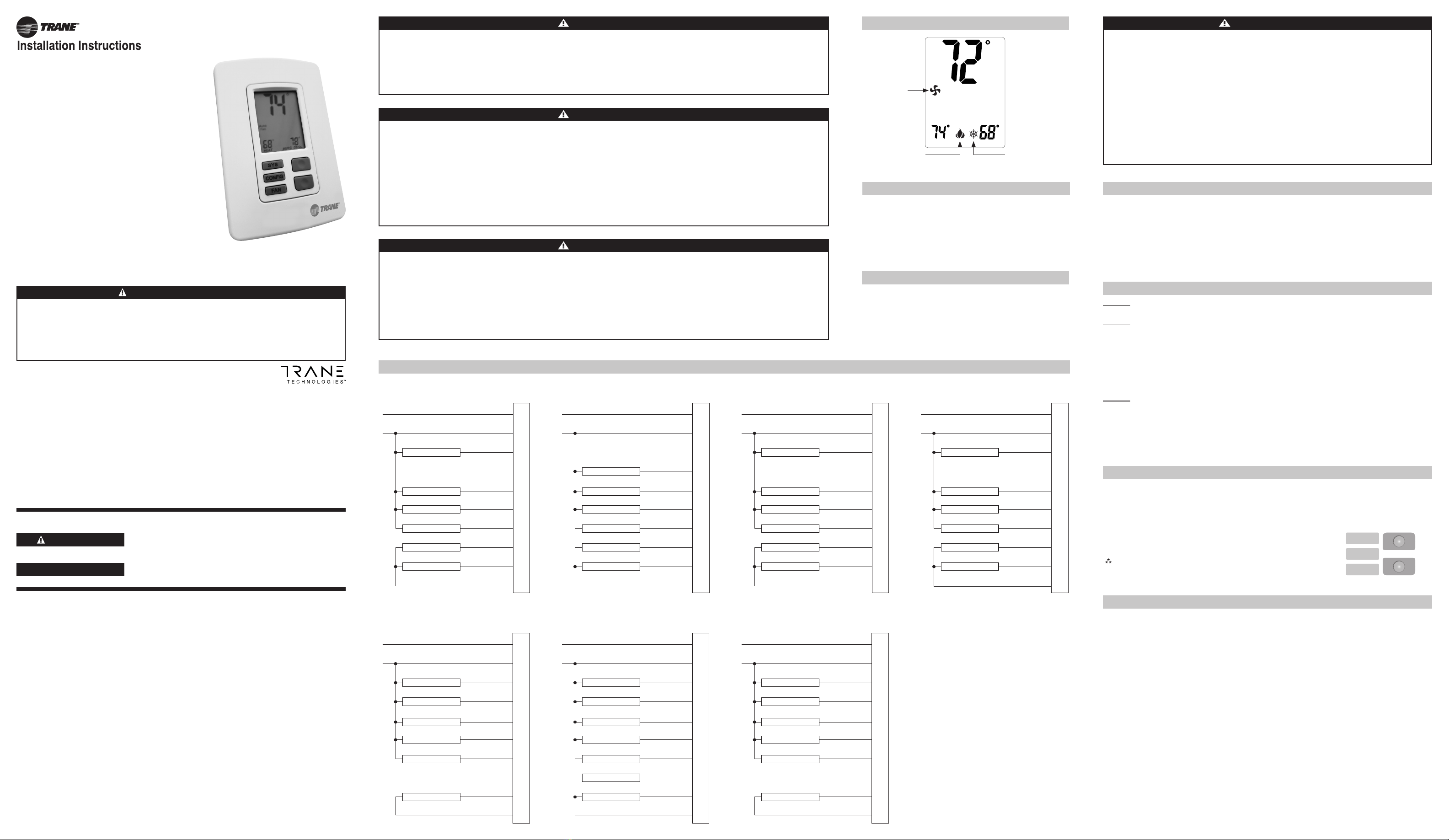
Icon Descriptions
Heating operation
icon
Cooling operation
icon
COOLHEAT
Fan
Auto
Fan
operation
icon
Proper Field Wiring and Grounding Required!
Failure to follow code could result in death or serious injury. All eld wiring MUST be performed by qualied
personnel. Improperly installed and grounded eld wiring poses FIRE and ELECTROCUTION hazards. To avoid
these hazards, you MUST follow requirements for eld wiring installation and grounding as described in NEC
and your local/state electrical codes.
WARNING
Personal Protective Equipment Required!
Installing/servicing this unit could result in exposure to electrical, mechanical and chemical hazards. Before
installing/servicing this unit, technicians MUST put on all Personal Protective Equipment (PPE) recommended
for the work being undertaken. ALWAYS refer to appropriate MSDS sheets and OSHA guidelines for proper PPE.
When working with or around hazardous chemicals, ALWAYS refer to the appropriate MSDS sheets and OSHA
guidelines for information on allowable personal exposure levels, proper respiratory protection and handling
recommendations. If there is a risk of arc or ash, technicians MUST put on all necessary Personal Protective
Equipment (PPE) in accordance with NFPA70E for arc/ash protection PRIOR to servicing the unit. Failure to
follow recommendations could result in death or serious injury.
WARNING
Follow EHS Policies!
Failure to follow instructions below could result in death or serious injury.
All Trane personnel must follow the company’s Environmental, Health and Safety (EHS) policies when
performing work such as hot work, electrical, fall protection, lockout/tagout, refrigerant handling, etc. Where
local regulations are more stringent than these policies, those regulations supersede these policies.
Non-Trane personnel should always follow local regulations.
WARNING
Wire Designator
Descriptions
R – 24 VAC Hot Black
C – 24 VAC Common White
W1 – Heat Red
Y1 – Cool Blue
GH – Fan High Purple
GM – Fan Medium Yellow
GL – Fan Low Gray
PS – Pipe Sensor (optional) Orange/White
RS – Remote Sensor Red/White
SC – Sensor Common Blue/White
C
W1
Y1
GH
GL
PS
SC
RS
R
GM
System 2
Cool Only
Gray
Blue/White
Remote Sensor
Pipe Sensor
Fan High
Cool
Fan Low
(Optional)
(Optional)
Purple
Blue
Yellow
Orange/White
Red/White
White
Black
24
VAC
Fan Medium
System 3
2-PipeManualChangeover
Blue/White
Remote Sensor
Pipe Sensor
Fan High
Heat/Cool
Fan Low
(Optional)
(Optional)
Purple
Yellow
Gray
Orange/White
Red/White
Red
White
Black
24
VAC
Fan Medium
C
W1
Y1
GH
GL
PS
SC
RS
R
GM
System 4
2-PipeSeasonalChangeover
Blue/White
Remote Sensor
Pipe Sensor
Fan High
Heat/Cool
Fan Low
(Optional)
(Required)
Purple
Yellow
Gray
Orange/White
Red/White
Red
White
Black
24
VAC
Fan Medium
C
W1
Y1
GH
GL
PS
SC
RS
R
GM
System 1
Heat Only
Remote Sensor
Pipe Sensor
Fan High
Heat
Fan Low
(Optional)
(Optional)
Purple
Yellow
Gray
Orange/White
Red/White
Blue/White
Red
White
Black
24
VAC
Fan Medium
C
W1
Y1
GH
GL
PS
SC
RS
R
GM
System 7
4-PipeAutoChangeover
Fan High
Cool
Heat
Fan Low
Purple
Yellow
Gray
Blue
Red
White
Black
24
VAC
Fan Medium
Blue/White
Red/White
Remote Sensor
(Optional)
C
W1
Y1
GH
GL
PS
SC
RS
R
GM
System 5
2-PipeManualChangeover
withAuxiliary
Remote Sensor
Pipe Sensor
Fan High
Auxiliary
Heat/Cool
Fan Low
(Optional)
(Required)
Purple
Yellow
Gray
Orange/White
Red/White
Blue
Red
White
Black
24
VAC
Fan Medium
Blue/White
C
W1
Y1
GH
GL
PS
SC
RS
R
GM
System 6
4-PipeManualChangeover
Fan High
Cool
Heat
Fan Low
Remote Sensor
(Optional)
Purple
Yellow
Gray
Blue/White
Red/White
Blue
Red
White
Black
24
VAC
Fan Medium
C
W1
Y1
GH
GL
PS
SC
RS
R
GM
Hazardous Service Procedures!
Failure to follow all precautions in this manual and on the tags, stickers, and
labels could result in death or serious injury. Technicians, in order to protect
themselves from potential electrical, mechanical, and chemical hazards, MUST
follow precautions in this manual and on the tags, stickers, and labels, as
well as the following instructions: Unless specied otherwise, disconnect all
electrical power including remote disconnect and discharge all energy storing
devices such as capacitors before servicing. Follow proper lockout/tagout
procedures to ensure the power cannot be inadvertently energized. When
necessary to work with live electrical components, have a qualied licensed
electrician or other individual who has been trained in handling live electrical
components perform these tasks.
WARNING
1. Turn off power to the heating and cooling system by removing the fuse or switching the appropriate
circuit breaker off.
2. Remove cover of old thermostat. This should expose the wires.
3. Label the existing wires with the enclosed wire labels before removing wires.
4. After labeling wires, remove wires from wire terminals or remove wire nuts.
5. Remove existing thermostat base from wall.
6. Refer to the following section for instructions on how to install this thermostat.
To Remove Existing Thermostat
Configuration Mode
The conguration mode is used to set the thermostat to match your heating/cooling system.
To congure the thermostat, perform the following steps:
1. Verify the thermostat is in the OFF mode. Press the SYS button until off mode displays.
2. Press the CONFIG button for 5 seconds while the thermostat is in OFF mode.
Press the up or down button to change settings within each screen.
Press the CONFIG button to advance to the next screen.
Note: Pressing the
SYS
button will return you to the previous screen.
To exit conguration mode, press the CONFIG switch for 5 seconds.
Configuration Mode Settings
1 – System
Select the type of operation you require.
1. Heat Only is for a system with only heating.
2. Cool Only is for a system with only cooling.
3. 2-Pipe Manual Changeover is for a 2 pipe system that handles both heating and cooling. The user
selects whether the system will be set to heating or set to cooling.
4. 2-Pipe Seasonal Changeover is for a 2 pipe system that handles both heating and cooling. The
thermostat selects whether the system will be set to heat or set to cool based on the pipe sensor
temperature. (Default)
5. 2-Pipe Manual Changeover with Auxiliary is for a 2 pipe system that handles both heating and
cooling. The user selects whether the system will be set to heat or set to cool. If set to heat and the
pipe sensor indicates there is not heat, the auxiliary output will be turned on.
6. 4-Pipe Manual Changeover is for a 4 pipe system. The user selects whether the system will be set
to heat, cool or off.
7. 4-Pipe Auto Changeover is for a 4 pipe system. The user selects whether the system will be set to
heat, cool, heat & cool or off.
FAN
SYS
CONFIG
Down
button
Up
button


