Trane Thermo King Magnum Plus User manual

Thermo King has a policy of coninuous product and data improvements and reserves the right to change design and specications without notice. We are
committed to using environmentally conscious print practices.
Thermo King – by Trane Technologies (NYSE: TT), a global climate innovator – is a worldwide leader in sustainable
transport temperature control solutions. Thermo King has been providing transport temperature control solutions
for a variety of applications, including trailers, truck bodies, buses, air, shipboard containers and railway cars since
1938. For more information, visit www.thermoking.com or www.tranetechnologies.com
©2020 Trane Technologies
TK 61110-4-OP Nov 2013
Operator’s Manual
Manuel de l’utilisateur
Manual del operador
Betriebshandbuch
Bruksanvisning
MagnumPlus
November 2013
Revision 0
TK-61110-4-OP

Magnum +
TK 61110-4-OP (Rev. 0, 11/13)
En


1
TABLE OF CONTENTS
TABLE OF CONTENTS
Table of Contents . . . . . . . . . . . . . . . . . . . . . . . . . 1
Safety Instructions . . . . . . . . . . . . . . . . . . . . . . . . 2
General Precautions .......................................... 2
Electrical Precautions ........................................ 2
Precautions ........................................................ 2
First Aid ............................................................ 3
Low Voltage ...................................................... 3
Identifying Unit Safety and Warning Decals .... 5
Locating Serial Numbers .................................. 5
Unit Inspection . . . . . . . . . . . . . . . . . . . . . . . . . . . 6
Specifications . . . . . . . . . . . . . . . . . . . . . . . . . . . . 8
System Net Cooling Capacity— Full Cool ....... 8
Evaporator Airflow Specifications .................... 8
MP-4000 Controller Specifications .................. 11
Physical Specifications ..................................... 13
Unit Description . . . . . . . . . . . . . . . . . . . . . . . . . . 14
Introduction ....................................................... 14
General Description .......................................... 14
Controller Description . . . . . . . . . . . . . . . . . . . . . 16
Controller Description ....................................... 16
Standard Display ............................................... 17
Glossary of Symbols ......................................... 18
Glossary of Mode Descriptions ........................ 19
Navigating the Controller Operating Menu . . . . . 22
Menu Scrolling Keys ........................................ 22
Initiating a Manual Defrost ............................... 23
PTI .................................................................... 24
Viewing Alarms/Warnings ............................... 24
Display Alternate Fahrenheit (F) or Celsius (C)
Temperatures .................................................. 24
Changing Setpoint ............................................ 24
Controller Back-up Battery ............................... 24
Operating Theory . . . . . . . . . . . . . . . . . . . . . . . . . 26
MAGNUM+ Operating Mode Function Chart . 26
Diagnosis: Troubleshooting, Warnings and Alarm
Codes . . . . . . . . . . . . . . . . . . . . . . . . . . . . . . . . . . 28
Introduction ....................................................... 28
Controller Diagnostics ...................................... 28
Emergency Cold Line . . . . . . . . . . . . . . . . . . . . . . 30
DECLARATION . . . . . . . . . . . . . . . . . . . . . . . . . 31

2
SAFETY INSTRUCTIONS
SAFETY INSTRUCTIONS
GENERAL PRECAUTIONS
• Always wear goggles or safety glasses.
Refrigerant liquid and battery acid can
permanently damage the eyes.
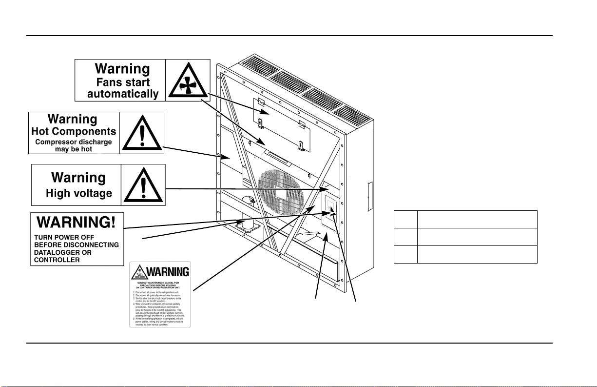
• Never operate the unit with the discharge
valve closed. Never close the compressor
discharge valve with the unit in operation.
• Keep your hands, clothing and tools clear of
the fans when the refrigeration unit is
running. If it is necessary to run the
refrigeration unit with covers removed, be
very careful with tools or meters being used
in the area.
• Never apply heat to a sealed refrigeration
system or container.
• Fluorocarbon refrigerants produce toxic
gases in the presence of an open flame or
electrical arc. The gases are severe
respiratory irritants capable of causing death.
• Firmly tighten all mounting bolts. Check
each bolt for correct length for their
particular application.
• Use caution when working around exposed
coil fins. The fins can cause painful
lacerations.
• Use caution when working with a refrigerant
or refrigeration system in any closed or
confined area with a limited air supply (for
example, a trailer, container or in the hold of
a ship). Refrigerant tends to displace air and
can cause oxygen depletion. This can result
in suffocation and possible death.
• Use caution and follow the manufacturer’s
suggested practices when using ladders or
scaffolds.
ELECTRICAL PRECAUTIONS
The possibility of serious or fatal injury from
electrical shock exists when servicing a
refrigeration unit. Extreme care must be used
when working with a refrigeration unit that is
connected to its power source. Extreme care
must be used even if the unit is not running.
Lethal voltage potentials can exist at the unit
power cord, inside the control box, inside any
high voltage junction box, at the motors and
within the wiring harnesses.
PRECAUTIONS
In general disconnect the units power cord
before repairing or changing any electrical
components.
Note that even though the controller is turned
off, one of the phases is still live and represents
a potential danger of electrocution
Where turning of the unit is not possible (for
example at voltage measuring or
troubleshooting), follow safety precautions
below.
• Turn the unit On/Off switch to Off before
connecting or disconnecting the unit power
plug. Never attempt to stop the unit by
disconnecting the power plug.
• Be certain the unit power plug is clean and
dry before connecting it to a power source.
• Use tools with insulated handles. Use tools
that are in good condition. Never hold metal
tools in your hand if exposed, energized
conductors are within reach.
• Do not make any rapid moves when working
with high voltage circuits. Do not grab a
falling tool or other object. People do not
contact high voltage wires on purpose. It
occurs from an unplanned movement.
• Treat all wires and connections as high
voltage until ammeter and wiring diagram
show otherwise.
• Never work alone on high voltage circuits on
the refrigeration unit. Another person should
always be standing by in the event of an
accident to shut off the refrigeration unit and
to aid a victim.
• Have electrically insulated gloves, cable
cutters and safety glasses available in the
immediate vicinity in the event of an
accident.

3
SAFETY INSTRUCTIONS
FIRST AID
IMMEDIATE action must be initiated after a
person has received an electrical shock. Obtain
immediate medical assistance.
The source of shock must be immediately
removed. Shut down the power or remove the
victim from the source. If it is not possible to
shut off the power, the wire should be cut with
either an insulated instrument (e.g., a wooden
handled axe or cable cutters with heavy
insulated handles). A rescuer wearing
electrically insulated gloves and safety glasses
could also cut the wire. Do not look at the wire
while it is being cut. The ensuing flash can
cause burns and blindness.
Pull the victim off with a non-conductive
material if the victim has to be removed from a
live circuit. Use the victim’s coat, a rope, wood,
or loop your belt around the victim’s leg or arm
and pull the victim off. Do not touch the victim.
You can receive a shock from current flowing
through the victim’s body.
Check immediately for the presence of a pulse
and respiration after separating the victim from
power source. If a pulse is not present, start
CPR (Cardio Pulmonary Resuscitation) and
call for emergency medical assistance.
Respiration may also be restored by using
mouth-to-mouth resuscitation.
LOW VOLTAGE
Control circuits are low voltage (24 Vac and 12
Vdc). This voltage potential is not considered
dangerous. Large amount of current available
(over 30 amperes) can cause severe burns if
shorted to ground. Do not wear jewelry, watch
or rings. These items can shortcut electrical
circuits and cause severe burns to the wearer.

4
SAFETY INSTRUCTIONS
2
BEN074
AXA0214
AXA0215
AXA0218
AXA0217
AXA0216
1
3
Nameplate and Warning Locations
1. Controller Nameplate
2. Unit Nameplate
3. Compressor Nameplate

5
SAFETY INSTRUCTIONS
IDENTIFYING UNIT SAFETY AND
WARNING DECALS
Serial number decals, refrigerant type decals
and warning decals appear on all Thermo
King®equipment. These decals provide
information that may be needed to service or
repair the unit. Service technicians should read
and follow the instructions on all warning
decals. See Figure .
LOCATING SERIAL NUMBERS
Serial numbers can be found on the
component’s nameplate.
•Electric Motor Nameplate: Attached to the
motor housing.
•Compressor Nameplate: On front of the
compressor.
•Unit Nameplate: On unit frame in power
cord storage compartment.
•MP-4000 Controller Nameplate: On top of
controller.

6
UNIT INSPECTION
UNIT INSPECTION
A closely followed maintenance program will help to keep your Thermo King unit in top operating condition.
The following service guide table should be used as a guide when inspecting or servicing components on this unit.
If a unit has been carrying cargo which contains a high level of sulphor or phosphorous (e.g. garlic, salted fish etc.), it is recommended that
clean evaporator coil after each trip.
Pretrip Inspect These Items
Electrical
• Perform a controller pretrip inspection (PTI) check.
• Visually check condenser fan and evaporator fan.
• Visually inspect electrical contacts for damage or loose connections.
• Visually inspect wire harnesses for damage or loose connections.
Refrigeration
• Check refrigerant charge.
Structural
• Visually inspect unit for damaged, loose or broken parts.
• Tighten unit, compressor and fan motor mounting bolts.

7
UNIT INSPECTION

8
SPECIFICATIONS
SPECIFICATIONS
SYSTEM NET COOLING CAPACITY— FULL COOL
EVAPORATOR AIRFLOW SPECIFICATIONS
MAGNUM+ Model — Air Cooled Condensing*
Return air to evaporator coil inlet
460/230V, 3 Phase, 60 Hz Power
Net Cooling Capacity Power Consump
60 Hz Capacity B/hr 60 Hz Capacity kW 60 Hz Power kW
21.1 C (70 F) 56,700 16.603 11.55
1.7 C (35 F) 40,945 11.990 11.03
-17.8 C (0 F) 24,785 7.258 7.57
-29 C (-20 F) 17,215 5.041 6.6
-35 C (-31 F) 14,000 4.104 6.03
*System net cooling capacity with a 38 C (100 F) ambient air temperature and R-404A.
460/230V, 3 Phase, 60 Hz Power 380/190V, 3 Phase, 50 Hz Power
Heating Capacity Heating Capacity
Watts Kcal/hr BTU/hr Watts Kcal/hr BTU/hr
MAGNUM+ normal 5,250 4,515 17,914 3,900 3,353 13,300
MAGNUM+ extended 7,250 6,234 24,738 5,550 4,772 18,937
*System net heating capacity includes electric resistance rods and fan heat.

9
SPECIFICATIONS
MAGNUM+
External Static
Pressure (water
column)
460/230V, 3 Phase, 60 Hz Power 380/190V, 3 Phase, 50 Hz Power
High Speed Low Speed High Speed Low Speed
m3/hr ft3/min m3/hr ft3/min m3/hr ft3/min m3/hr ft3/min
0 mm (0 in.) 6,560 3,860 3,170 1,865 5,480 3,225 2,710 1,595
10 mm (0.4 in.) 5,820 3,425 1,770 1,040 4,530 2,665 930 545
20 mm (0.8 in.) 5,000 2,940 — — 3,750 2,205 — —
30 mm (1.2 in.) 4,430 2,610 — — 2,930 1,725 — —
40 mm (1.6 in.) 3,520 2,070 — — 1,870 1,100 — —
Compressor Motor:
Type 460/380V, 60/50 Hz, 3 Phase
Kilowatts 4.48 kW @ 460V, 60 Hz
Horsepower 6.0 hp @ 460V, 60 Hz
RPM 3550 RPM @ 460V, 60 Hz
Locked Rotor Amps 70 amps @ 460V, 60 Hz
Condenser Fan Motor:
Type 460/380V, 60/50 Hz, 3 Phase
Kilowatts 0.55 kW @ 460V, 60 Hz
Horsepower 0.75 hp @ 460V, 60 Hz
Number: All Models 1
Motor:
RPM 1725 RPM @ 460V, 60 Hz
Full Load Amps 1.0 amps @ 460V, 60 Hz; 1.0 amps @ 380V, 50 Hz

10
SPECIFICATIONS
Locked Rotor Amps 3.9 amps @ 460V, 60 Hz; 3.7 amps @ 380V, 50 Hz
Evaporator Fan Motors:
Type 460/380V, 60/50 Hz, 3 Phase
Kilowatts 0.75 kW @ 460V, 60 Hz
Horsepower 1.0 hp @ 460V, 60 Hz
Motor:
RPM (Each): High Speed 3450 RPM @ 460V, 60 Hz
Low Speed 1725 RPM @ 460V, 60 Hz
Full Load Amps (Each): High Speed 1.6 amps @ 460V, 60 Hz
Low Speed 0.8 amps @ 460V, 60 Hz
Locked Rotor Amps: High Speed 10.5 amps @ 460V, 60 Hz
Low Speed 9.0 amps @ 460V, 60 Hz
Electrical Resistance Heater Rods:
Type 460/380V, 60/50 Hz, 3 Phase
Number
Normal Capacity
Normal Capacity
Extended Capacity
6 (18 ga wire)
3 (18 ga wire)
3 (16 ga wire)
Watts (Each):
Normal Capacity
Normal Capacity
Extended Capacity
680 Watts @ 460V, 60 Hz
1360 Watts @ 460V, 60 Hz
2000 Watts @ 460V, 60 Hz
Current Draw (Amps) 5 amps total @ 460V across each phase at heater contractor
Control Circuit Voltage:
29 Vac @ 60 Hz

11
SPECIFICATIONS
MP-4000 CONTROLLER SPECIFICATIONS
Temperature Controller:
Type MP-4000 is a controller module for the Thermo King Magnum+ Unit. Additional
requirements can be met by means of expansion modules. The MP4000 is solely
responsible for temperature regulation of the reefer container, but other monitoring
equipment can be used in conjunction with the MP 4000 - such as a chart recorder.
Setpoint Range -40.0 to +30.0 C (-31.0 to +86.0 F)
Digital Temperature Display -60.0 to +80.0 C (-76.0 to +176.0 F)
Controller Software (Original Equipment):
Version See controller identification decal
Defrost Initiation:
Evaporator Coil Sensor Manual Switch or Demand Defrost Initiation: Coil must be below 18 C (65 F).
Defrost cycle starts when technician or controller requests defrost initiation.
Timed Defrost Initiation: Coil must be below 4 C (41 F). Defrost cycle starts 1
minute after the hour immediately following a defrost timer request for defrost
initiation. For example, if the defrost timer requests a defrost cycle at 7:35, the
defrost cycle will start at 8:01. Datalogger will record a Defrost event for each interval
in which a Defrost cycle is pending or active (i.e. both the 8:00 and 9:00 data logs).
Demand Defrost Demand defrost function initiates defrost when:
Temperature difference between the return air sensor and defrost (evaporator coil)
sensor is too large for 90 minutes
Temperature difference between the supply air sensors and return air sensor is too
large
Defrost Timer:
Chilled mode
Evaporator Coil Temperature must be below 5C (41 F) to activate the defrost
compressor hour timer.

12
SPECIFICATIONS
Chilled Mode (continued) There is an interval set for defrosting, however, the defrost timer is built intelligent - it
detects whether or not there is ice building up on the coil. If there is no ice building up
on the coil, it extends the defrost interval, and if there is Ice building up earlier on the
coil it reduces the defrost interval. The maximum interval is 48 hours.
Frozen mode Every 8 hours of compressor operation. Defrost interval increases 2 hours each
timed defrost interval. Maximum time interval in Frozen mode is 24 hours.
Reset to Base Time Defrost timer resets if the unit is off more than 12 hours, setpoint is changed more
than 5 C (9 F) or PTI pretrip test occurs.
Defrost Termination:
Defrost (Coil) Sensor Chilled mode: Terminates defrost when coil sensor temperature rises to 18 C (65 F).
Frozen mode: Terminates defrost when coil sensor temperature rises to 18 C (65 F).
Termination Timer Terminates defrost after 90 minutes at 60 HZ operation if coil sensor has not
terminated defrost (120 minutes at 50 Hz operation)
Power Off Turning Unit On/Off switch Off terminates defrost
MP-4000 CONTROLLER SPECIFICATIONS (CONTINUED)

13
SPECIFICATIONS
Compressor Shutdown Protection (Auto Reset):
Stops Compressor 148 C (298 F)
Allows Compressor Start 90 C (194 F)
Bulb Mode:
Evaporator Fan Speed Settings Flow High: High speed only
Flow Low: Low speed only
Flow Cycle: Fans will cycle between low and high speed every 60 minutes
Defrost Termination Temperature Setting 4 to 30 C (40 to 86 F)
PHYSICAL SPECIFICATIONS
Fresh Air Exchange Venting System (Adjustable):
MAGNUM+ 0 to 225 m3/hr (0 to 168 ft3/min.) @ 60 Hz
0 to 185 m3/hr (0 to 139 ft3/min.) @ 50 Hz
Evaporator Fan Blade Specifications:
MAGNUM+:
Diameter 355 mm (14.0 in.)
Pitch 25°
Number of Fans 2
Weight (net):
MAGNUM+ Base Unit 380 Kg (875 lb.)
Water-cooled Condenser-Receiver Option 13.6 Kg (30 lb.)
MP-4000 CONTROLLER SPECIFICATIONS (CONTINUED)

14
UNIT DESCRIPTION
UNIT DESCRIPTION
INTRODUCTION
This chapter will briefly describe the following
items:
• General Unit Description.
• Standard Component Descriptions.
• Optional Component Descriptions.
GENERAL DESCRIPTION
MAGNUM units are all-electric, single-piece,
refrigeration units with bottom air supply. The
unit is designed to cool and heat containers for
shipboard or overland transit. The unit mounts
in the front wall of the container. Fork lift
pockets are provided for installation and
removal of the unit.
The frame and bulkhead panels are constructed
of aluminum and are treated to resist corrosion.
A removable evaporator compartment door
provides service access. All components except
the evaporator coil and electric heaters can be
replaced from the front of the unit.
Each unit is equipped with an 18.3 m (60 ft.)
power cable for operation on 460-380V/3 Ph/
60-50 Hz power. The unit power cable is stored
below the control box in the condenser section.
Each unit is equipped with 460-380V/3 Ph/
60-50 Hz electric motors. An automatic phase
correction system provides the proper electrical
phase sequence for condenser fan, evaporator
fan and compressor operation.
Figure 1: MAGNUM+ Unit
BEN074

15
UNIT DESCRIPTION
The MAGNUM+ container unit features the
following components:
• Scroll Compressor
• Compressor Digital Control Valve
• Economizer Heat Exchange System
• Temperature Sensors
• Fresh Air Exchange System
• Receiver Tank Sight Glass
• Evaporator Fans
• Condenser Fan Control
• Suction/Discharge Pressure Sensor
(Optional)
• Remote Monitoring Receptacle Option
(4-pin) (optional)
• Remote Monitoring Modem (RMM,
RMM+) (Optional)
• USDA Cold Treatment Temperature
Recording (Optional)
• Advanced Fresh Air Management (AFAM)
and Advanced Fresh Air Management Plus
(AFAM+) (Optional)
MP-4000 Controller
The MP-4000 is an advanced microprocessor
controller that has been specially developed for
the control and monitoring of refrigeration
units. See “Controller Description and
Operating Chapter” for more detailed
information.
1
BEN074
1. MP-4000 Controller
Figure 2: MP-4000 Controller

16
Controller Description
CONTROLLER DESCRIPTION
The MP-4000 is an advanced microprocessor
controller. It has been specially developed for
the control and monitoring of refrigeration
units. The controller contains the following
basic features:
Temperature/Message Status Display:
• Temperature area. Displays Return air
sensor, Supply air sensor, and Setpoint
• Message area. Displays Alarms, Message
and Controller menu
Keypad:
• F1 – F4 Function keys navigate within the
Status Display
• 2 Status LED indicators
• Special Function keys. ON/OFF, PTI,
Defrost
Controller Back-up Battery
Every Controller has a Back-up Battery. This
will allow the controller to be energized if the
unit is not connected to shore power. The
technician can change settings in the controller
- Setpoint, etc.
Press the ON/OFF key, the controller will
energize and stay energized for 25 sec, by
pressing any of the Menu keys the 25 sec timer
will reset to 20 sec.
Controller Input and Output Signals
The MP-4000 microprocessor controls all unit
functions to maintain the cargo at the proper
temperature. The controller also monitors and
records system faults and performs pretrip.
The MP-4000 controller uses advanced
solid-state integrated circuits to monitor and
control unit functions. The controller monitors
inputs from:
• Return Air Sensor
• Supply Air Sensor
• Evaporator Coil Sensor
• Condenser Coil Sensor
• Ambient Sensor
• Humidity Sensor
• USDA (Spare) Sensors 1, 2 and 3
• Compressor Discharge Line Temperature
Sensor
• High Pressure Cutout Switch/Discharge
Pressure Sensor
• Low Pressure Cutout Switch/Suction
Pressure Sensor
• Phase measuring circuits
• Current measuring circuits
• Voltage measuring circuits
Output signals from the controller
automatically regulate all unit functions
including:
• Compressor operation
• Condenser fan operation
• Evaporator fan motor operation
• Compressor digital valve
• Vapor injection valve
• Dehumidify valve
• Electric heaters
• Phase selection

17
Controller Description
STANDARD DISPLAY
The Standard Display is a ¼ VGA graphical
type display. The temperature can be displayed
in Celsius or Fahrenheit.
The standard display will display the
controlling sensor and Setpoint. The Setpoint
will be the low reading with the C or F.
Once a key is pressed the Standard display will
change to the Unit Status Display. After 2 min
of no key activity the display will return the
Standard display
Standard Display
Idle Screen
After approximately 30 seconds of inactivity
the display will go into hibernation and one of
the following symbols will be displayed.
Display alternates between the Idle screen and
the standard display during this time.
The happy face => everything is ok
The Disgruntled face => we do have a
warning
The unhappy face => we do have an
alarm
Check Mark Symbol
The check mark symbol
indication that a SmartPTI has
recently been running and no
problems was found. The
thumb will only be shown in
the normal operation state.
This symbol will appear at the
left hand corner of the idle screen display.
1. Standard Display
2. Function Keys
3. Special Function Keys
MP-4000 Controller Display Panel
3
2
1
This manual suits for next models
2
Table of contents
Other Trane Truck manuals
Popular Truck manuals by other brands

allen
allen AT-16 Safety & operation manual

Super Products
Super Products Camel 1200 (Ejector Unloading) Operator's manual

Chevrolet
Chevrolet 10 1971 Series Chassis Service Manual

Verhagen Leiden
Verhagen Leiden MULTI MOVER L+ User manual and parts list

DongFeng
DongFeng DFA1063DJ10-301 Service manual

Terex
Terex Digger Derrick Operator's manual