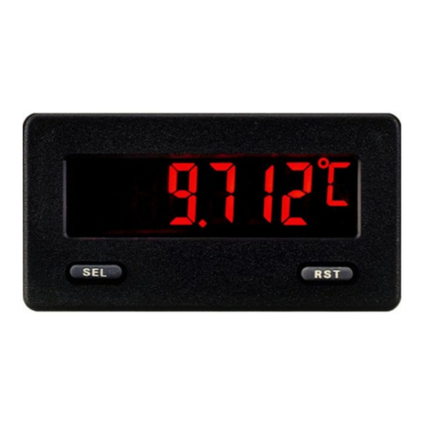
Transforming Technologies Ohm Metries SRM320 User manual

T R A N S F O R M I N G T E C H N O L O G I E S , L L C
O U T S T A N D I N G A L T E R N A T I V E S I N S T A T I C C O N T R O L
Pock e t St a t ic Fie ld M e t e r
Model SRM320
I nstruction Manual
Ohm Metrics™

Con t en t s
1D escr ipt ion
SRM320 1
Ohm Met rics 1
2Operat ion
Underst anding Surface Resistivit y 2
Reading Met er Result s 3
Operat ion: I nternal Elect rodes 5
Operat ion: Ext ernal Electrodes 5
Resist ance Between Two Points 6
Resist ance to Ground 7
Volum e Resist ance 8
3Specifica t ion s 9
4Service and W arrant y 10

1
Ohm Metrics Pocket Resistance Meter:
SRM 320
The SRM320 Surface Resistance Met er is an easy t o use
t est er for m easuring surface resist iv it y. This SRM 320 uses
parallel electrodes and concent ric rings to accurately
m easure RTT, RTG, or resist ivit y for periodic verificat ion,
fact or y audit s or t est lab ev aluat ion of pr oduct .
This m et er is designed t o be used in all facet s of m at erial
product ion including engineering, m aintenance, qualit y
cont rol, incom ing inspect ion, m anufact uring, research, or
sales depart m ent s for t he test ing of ant i- static m at s, floor
finishes, paint s, wrist st raps, sm ocks, foot wear, bags and
cont ainers.
The SRM310 m eets periodic t est requirem ent s per Com pli-
ance Verificat ion ESD TR53 and confor m s t o ANSI / EOS/
ESD ( S4.1, S7.1, S12.1, S2.1) .
Ohm Met rics t est and m easurem ent product s, from
Transform ing Technologies, are useful, reliable tools for
charact erizing and ident ifying t he elect rical resist ance of
m at erials and t he per form ance of personal grounding
product s.
All Ohm Met rics product s are designed to support ESDA
Com pliance Ver ificat ion TR53.
All Ohm Met rics product s can be calibrat ed.
All Ohm Met rics test and m easurem ent product s are
warrant ed for 1 full year.

2
Un der st a n din g Sur fa ce Re sist iv it y
For ESD purposes, m at erials are classified by t heir resist ance
t o the m ovem ent of elect ricit y. The following ranges and
definit ions ar e found in ESD Associat ion or EI A st andar ds
publicat ions.
Condu ct ive m a t e ria ls: Wit h a low elect rical resist ance,
elect rons flow easily across the surface or through t he bulk
of t hese m at erials. Charges go t o ground or t o another con-
ductive obj ect t hat t he m aterial cont acts or com es close t o.
Conductive m at erials have a surface resist ivit y less than 1 x
105 Ω/sq or a v olum e resist ivit y less t han 1 x 10⁴ Ω- cm .
D issipa t iv e m a t er ia ls: For t hese m at erials, t he char ges
flow t o ground m ore slow ly and in a som ewhat m ore con-
t rolled m anner t han w it h conduct ive m at erials. Dissipat ive
m at erials
have a surface resist ivit y equal t o or great er t han 1 x 10⁵ Ω/
sq but less t han 1 x 10¹² Ω/sq or a volum e resist iv it y equal
to or greater t han 1 x 10⁴ Ω- cm but less than 1 x 10¹¹ Ω-
cm .2
I n su la t iv e m a t er ia ls: I nsulat ive m at er ials prev ent or lim it
the flow of electrons across their surface or t hrough their
volum e. I nsulat ive m at erials have a high elect rical resist ance
and are difficult t o gr ound. St at ic charges rem ain in place on
t hese m at erials for a very long t im e. I nsulat ive m at er ials
are defined as those having a surface resist ivity of at least 1
x 1012 Ω/sq or a volum e r esist iv it y of at least 1 x 1 011 Ω- cm .

3
Re ad in g M et e r Resu lt s
The LED light s on t he m et er indicat es how
m uch resist ance a surface has and if it is
“Conductive”, “Dissipative” or “Insulating”
by flashing colored LED light s. The t ester
value is indicat ed on t he LED display in
Ohm s or Ohm s per square inch.
DECADE SCALE
103= 1 kilohm
104= 10 kilohm s
105 = 100 kilohm s
3 x 105= 300 kilohm s
106= 1 m eg ohm
3 x 106= 3 m eg ohm
107= 10 m eg ohm s
3 x 107= 30 m eg ohm s
108= 100 m eg ohm s
3 x 108= 300 m eg ohm s
109= 1000 m eg ohm s
3 x 109= 3000 m eg ohm s
1010 = 10,000 m eg ohm s
1011 = 100,000 m eg ohm s
1012 = 1,000,000 m eg ohm s
TEST VOLTAGE
The test volt age ranges are 10v and 100v. According t o
ESDA st andards S4.1, S7.1, and S11.11, 10 volts should be
applied for conduct ive surfaces less t han 106and 100v for
COLOR I N D I CAT I N G FU N CTI ON ohm
Green Conductive 103-105
Yellow Dissipative: ideal test measurement 3 x 10⁵- 109
Orange Dissipative but nearing insulative level 3 x 10⁹–1010
Red Near insulative to insulative 1011 - 1012
The Decade Scale is
short han d for elect rical
m easurem ent s, dis-
played in powers of 10.
Half decades provide
great er accuracy by giv-
ing a closer indicat ion t o
t he m easur em ent value.
A decade will bright en
to t he according test
result. Colors signify the
test value’s function.

4
m at erials 106or gr eat er . The SRM320 w ill aut om at ically
generat e proper volt age according t o t est m easurem ent .
TEM PERATURE AN D H UM I D I TY
Hum idit y and tem perat ure affect the elect rical propert ies
of t he m ost m at erials being t est ed. I t is possible to test or
m anufact ure a m at er ial at high hum idit y and pass all t he
t est specificat ions, but w hen t he cust om er r eceives t he
m at erial and used it at a lower hum idit y or tem perat ure
t he m at er ial fails t o pass the specificat ions. This can cause
rej ect s and loss of pr oduct . ANSI / ESD Associat ion and
Eur opean CECC recognize t he env ironm ent al effect s t o t est
m easurem ents and specify in their st andards t hat t hey
m easured and recorded.
At high hum idit y a t hin lay er of w at er is condensed or ab-
sorbed on or in t he m aterial and w ill increase the elect rical
conduct iv it y. Conver sely, t he com binat ion of low hum idit y
and low t em perat ure will give t he m at erial t he highest
elect r ical r esist ance result s ( or slow est dissipat ion t im es) .
At elevat ed t em per at ures t he m obilit y of free elect rons is
increased t hereby increasing t he m at erials conduct iv it y.
When t he m at erial is at a lower t em per at ure, built in
st resses occur which m ight increase t he resist ance due t o
increased dist ance between t he conductive addit ives.
Thus, hum idity and tem perature m ust be known and
should be recorded wit h t est result s.
Op er at ion
The SRM320 can t est m at erials in t wo ways, using int ernal
parallel resist ivit y probes locat ed on t he back of t he m et er
or w it h ex t er nal 5lb elect r ode probes ( sold separat ely) .

5
Op er at ion : I nt e rn al Ele ct r ode s
The parallel resist ivit y probe m et hod
com plies wit h EOS/ ESD- S11.11. I t is
used t o giv e fast elect r ical resist iv it y
m easurem ents on flat hom ogeneous
m at erials. I t m ay be used on m ult ilay-
ered m at erials, but t his should be not ed
along wit h t he tem perat ure and hum idit y
value on t he dat a repor t. When t he
m easurem ent is t aken bet ween t he
tester’s two mesh rails under the tester, the tester will in-
dicat e t he surface resist ivit y of t he m at er ial being t est ed.
1. Prior t est ing, m ake cert ain t hat surfaces t o be
t est ed are clean and free of cont am inant s.
2. Allow the m et er t o equilibrat e to t he at m osphere
the m et er is to be used in. I t m ay t ake a half hour
for t he m et er t o adj ust t o envir onm ent condit ions.
3. Place the m et er on t he desired surface t o be test ed
and press and hold the red t est button.
4. When using t he built - in electrodes, the meter’s test
values for surface resist ivit y are in ohm s per square
( alt hough t hey ar e displayed in ohm s) .
5. The test value is indicated on t he LED display. A
decade will br ight en t o t he accor ding t est value.
6. Colors signify the test value’s function (see page 3).
Op er at ion : Ex t er na l Ele ct r ode s
By connect ing t he opt ional surface resis-
tance probes to the SRM320 meter, it’s
possible t o m easure other form s of re-
sist ance su ch as Point t o Point ( RTT) Re-
sist ance, Surface t o Gr ound ( RTG) , and
Volum e Resist ance. Using these probes
will allow com pliancy wit h var ious st an-

6
dards including ANSI / ESDA S4.1 for Work surface –Resist ance
Measurem ent , ANSI / ESDA S7.1 Resist ive Charact er izat ion of
Materials - Floor Materials.
N ot e : W h en t h e m e a su r em e nt is t a k en u sin g t he 5 lb e x -
t e rn a l pr obes, t he t e st er w ill in dica t e t h e r e sist a nce of
t h e m a t er ia l in oh m s.
Re sist a n ce be t w e en Tw o Poin ts ( RTT)
RTT m easurem ents can be used for t he evaluat ion of floors,
chairs, cart s, work surfaces and ot her ESD cont rolled m at er ials
and products.
1. Connect one end of each of t he banana test leads int o
the socket s of the m et er.
2. Connect ot her end of t he t est coil cords in t o t he 5 pound
probes.
3. Place bot h probes on
t he m at er ial according
to t est procedures or
st andard being used -
nor m ally 3 feet ( 36
inches) apart .
4. Press the “TEST” but-
ton and the value will
be displayed on t he
LCD. The m et er will
apply t he cor rect volt -
age ( 10v or 100v) according t o t he value of what is
m easured.
5. When perfor m ing t est do not t ouch lead wires or probes.
Avoid over lapping of lead wires. This will ensure accurat e
readings.

7
M ea su rin g r esist a nce t o gr ou nd ( RTG)
Resist ance t o gr ound m easures t he elect rical pat h bet ween a
point on a sur face t o electrical ground. I t can be used for t he
evaluat ion of floors, chair s, cart s, wor k surfaces and ot her ESD
cont rolled m at erials and product s.
1. To test RTG on a surface, connect the first lead to t he
m et er and to a 5lb probe and put probe on t he surface.
Connect t he 2nd lead t o the m et er and t o a groundable
point ( RTGP) .
2. To at t ach lead to RTGP, slip t he alligat or clip t o t he lead
and connect it t o t he ground snap or connect the banana
plug t o a com m on point ground plug.
3. Press the “TEST” button and the value will be displayed
on t he LED. When perform ing t est do not touch lead
wires or probe. Avoid overlapping of lead wires. This will
ensure accurat e readings.
4. Resist ance values are in ohm s. When recor ding test val-
ues also not at e t he tem perat ure and hum idity as the en-
vironm ent can affect t est r esult s.

8
Volu m e Re sist a nce M e a su r em e nt
Volum e Resist ance m easures t he elect rical pat h through a
m at erial. N ot e : Th is m et h od r e quir es a m e t al p la t e ( su ch
a s st a in le ss st e e l) t h at is n ot su pp lie d by Tr an sfor m in g
Te chnologies.
1. Connect one end of each of t he banana test leads int o
the socket s of the m et er.
2. Connect t he ot her end of the t est coil cords into 5
pound probes.
3. Place sam ple m at erial on a conduct ive m et al plate.
Place one of the 5 pound probes on t he m aterial so t hat
the m at erial is sandw iched between the probe and
m et al plat e. ( see below)
4. Place t he second 5 pound probe on t he conduct ive
m et al plat e.
5. Press the “TEST” button and the value will be displayed
on the LED. Volum e Resist ance is in ohm s- cm .

9
SPECI FI CATI ON
Dim ension: approx. 70m m x 130m m x 35m m
Weight : approx. 103 gram s
Power: Bat t ery operat ed PP3 9 volt
Connect ions: 2 x 3.5m m j ack plug for each ear th connec-
tion
Test Range: 103 t o 1012
Dissipat ive Range: 3 x 10⁵ to 3 x 10⁹ 1/ 2 Decade bet ween
each decade on a logarithm ic scale
Exam ple: 1x 105 x 3.21 = 3 x 10⁵ ( 1/ 2 Decade Meas-
urem ent) x 3.21 = 1 x 10⁶
Measurem ent : Sur face Resist iv it y ( Ohm s per squar e)
Point t o Point Resist ance ( Ohm s)
Accuracy: + / - 0.5 Decade in Conductive Range
+ / - 0.25 Decade in Dissipat ive Range

About Transform ing Tech nologie s
Since 1998, Transform ing Technologies has helped elec-
tronic m anufact uring facilit ies t o prot ect their products and
processes fr om t he m any serious problem s associat ed wit h
st at ic elect r icit y .
Transform ing Technologies offers a wide range of unique
and out standing product s t o det ect , prot ect , elim inat e and
m onit or elect rost at ic charges. Our product s are int egral com -
ponent s of an eff ect iv e st at ic cont rol pr ogr am .
Se rvice a nd W a rr an t y
Transfor m ing Technologies, LLC provides a lim it ed war-
rant y for the Model SRM320. All new product s are guaranteed
t o be fr ee from defect s in m at erial and workm anship for a pe-
riod of one ( 1) year from t he dat e of shipm ent . Liabilit y is lim -
it ed t o servicing ( aft er evaluat ing, repairing or replacing) any
product ret urned t o Transform ing Technologies. The com pany
does not warrant dam age due t o m isuse, neglect, alt erat ion
or accident . I n no ev ent shall Transfor m ing Technologies be
liable for collat er al or consequent ial dam ages.
To receive service under warrant y , please contact Trans-
form ing Technologies Technical Support .
Phone: 419-841-9552
Fax: 419-841-3241
E-mail: info@ transf orming-technologies.com
3719 King Rd.
Toled o, O hio 4 3617
TRA N SFO RM IN G TECH N O LO G IES, LLC
Table of contents
Other Transforming Technologies Measuring Instrument manuals

Transforming Technologies
Transforming Technologies Resistance RANGER CM2800 User manual
Transforming Technologies
Transforming Technologies Ohm Metrics SRM 310 User manual
Transforming Technologies
Transforming Technologies OhmMETRICS EFM250 User manual
Transforming Technologies
Transforming Technologies Ohm Metrics EFM115 User manual
Transforming Technologies
Transforming Technologies GTS600 User manual
Transforming Technologies
Transforming Technologies WST 200 User manual
Transforming Technologies
Transforming Technologies Ohm Metrics SRM330 User manual
