Transforming Technologies Resistance RANGER CM2800 User manual

Instruction Manual
RangerBOSS Network Ready Constant Monitor
Model CM2800

Contents
1Description
CM2800 1
Features 1
2Installation
Installation Instructions 2
Installation Diagram 3
3Operation
Wrist Strap Indications 5
Mat Indications 6
GND monitor Indications 6
Maintenance 6
4Specifications 7
6Service and Warranty 9

Ohm Metrics Resistance Monitor: CM2800
The Ohm Metrics' CM2800 Series dual conductor workstation moni-
tor provides continuous monitoring of voltage and resistance for two
wrist straps along with two mat and two workstation tool grounds.
The status’ are displayed using tricolor LED’s on the front panel of
the monitor and abnormal levels trigger an alarm to inform opera-
tors on the line. Utilizing low-voltage, resistive loop technology, and
dual conductor ground products, the CM2800 is an extremely sensi-
tive and reliable ground monitoring for use in highly critical areas.
The CM2800’s alarm settings can be reconfigured quickly and easily
with the optional PC software CM2800-SEE. Operator Resistance,
Operator Voltage, Work-surface Resistance, Operator Presence
Check (OPC) and Resistance of Equipment alarms can be enabled/
disabled and limits selectable to user specifications.
The CM2800 is network ready and can easily be connected to other
workstation monitors and a computer using the high speed network
router, CM2800-H. The host computer can be transformed into a
command center with the software CM2800-BOSS SEE, a central
monitoring program that shows real time grounding results and al-
lows for adjustment of alarm parameters of up to 4096 workstations.
An entire assembly line’s ESD protection can be remotely monitored
and adjusted with one computer.
Features:
Monitors two wrist straps, work surfaces and tools.
User programmable alarm levels
Network Ready
Ultra-Low voltage for highly critical areas.

Operation
The CM2800 monitors the grounding functions of a workstation and
alerts users when levels are out of the set range. The CM2800 has the
capabilities to monitor:
Operators: Resistance and voltage of two wrist straps/personnel,
Work surfaces: Resistance levels of two dissipative surfaces.
Tools: Resistance levels of two grounded work station tools.
Alerts
If any parameters exceed the preset high limits, the corresponding LED
on the front panel of the monitor will change color from green (OK) to
red (high warning) to indicate the abnormal situation. If the resistance is
below preset low limit, the LED color will be yellow (low warning).
An audible alarm will sound, in addition to the corresponding LED indi-
cator when the resistance is in an abnormal state. For instant differen-
tiation, a single beep will sound if the abnormal situation occurs on
“Station 1” whereas a double beep sound for “Station 2”.
(LED indicators illustration of GZ-1800 front panel.)
“OP 1” - Grounding resistance of operator 1
“OP 2” - Grounding resistance of the operator 2
“V1” Induced voltage on operator 1 .
“V2” Induced voltage on operator 2.
“MAT1” Grounding resistance of work surface 1
“MAT2” Grounding resistance of work surface 2
“G1” Grounding resistance of tool 1
“G2” Grounding resistance of tool 2

3
1. Operator Grounding
The operator is grounded when the dual conductor wrist strap is
plugged in to the jack labeled “OP” of the grey remote. The corre-
sponding LED label “OP” and “V” will be GREEN if levels are normal.
If the any of these parameters exceed preset high limits, the corre-
sponding LED will turn RED and alarm will sound. If the resistance of
the wrist strap is below preset low limit, the LED will turn YELLOW
and alarm. If the wrist strap is not plugged into the remote termi-
nal jack, the LED’s of both “OP” and “V” will be off to indicate the
stand-by mode. Factory set resistance limit is 1.8 megohm. De-
fault Voltage limit is 2V .
Since the CM2800 is designed with a Ultra-Low Voltage circuit, the
measurement voltage of the grounding resistance of the operator
body can be as low as 0.2V. Therefore, when the low resistance of
the wrist strap is measured, it may be affected by the small
“Battery Effect” existed between the contact of the human body
skin and the wrist-strap metal stud. To avoid this, the the low resis-
tance measurement is disabled by default. If this measurement is
turned on and the value is affected, you can reverse the direction
of the wrist strap stud to resolve the influence.
Operator Presence Check (OPC) Alert
Stand-By Mode (or “idle mode”) is when the monitor is powered
on, and there is no wrist straps plugged in to the remotes. At this
time, the monitor will start Operator Presence Check (OPC) if en-
abled. OPC is a pre-programmed count down that will trigger an
alarm if the operator does not plug in the wrist strap into the re-
mote jack in the specific time. The LED of “OP” and “V” will turn red
and flash to indicate an OPC warning. OPC warning will stop after a
wrist strap is plugged in to the remote.

4
If the cable connecting to a wrist strap remote is unplugged or sev-
ered at either end, the monitor’s audible alarm will sound, and the
corresponding “OP” LED will turn red.
Note: Each remote has two jacks labeled “OP” and “AUX”. The “OP”
jack is monitored and “AUX” jack is not, but provides a grounding
path for one more wrist strap. The status of “AUX” will not affect
“OP”.
2. ESD Mat
The CM2800 can monitor the ground resistance of two dissipative
surfaces. When the resistance is within acceptable limits, the LED
labeled “MAT” will be GREEN. If it exceeds preset high limits, the
LED will change to RED and an alarm will sound. Factory limits are
set at 100 meg ohm.
3. Tool
The CM2800 monitor measures the low value grounding resistance
of equipment or a tools in the range of 2 to 20 Ohm. Typical exam-
ples of equipment are electronic microscope or test instruments.
When the resistance is within acceptable limits, the LED labeled “G”
will be GREEN. If it exceeds preset high limits, the LED will change
to RED and an alarm will sound. Only 100 microamperes of current
are used for this measurement, and as a result only 4mV of poten-
tial is induced on the instrument being monitored.

5
Installation
Before you install your device, check for the items below:
1 - CM2800 workstation monitor
2 - Remote Jacks
1 - Power Supply
2 - Telephone Cables
3 - Grounding Cables: FM1515, FM1515CM, FM1515NR
Please carefully read the following instructions before proceeding
with product installation.
1. Install monitor in a location where alarm indicators will be visi-
ble and alarm will be audible to operator. Typical locations are
under a workstation table or low shelf.
2. Mount monitor securely in place with Velcro.
3. Install remote wrist strap terminals in a convenient location for
operators. Frequently remotes are mounted on the underside
of the workbench nearest operators.
5. Plug the telephone cable from the left remote to the OP1 on
the back of monitor.
6. Plug the telephone cable from the right remote to the OP2 on
the back of monitor.
7. Connect the bare end of the FM1515CM wire to the terminal
on the back of the monitor labeled GND and connect to
GROUND. See wiring diagram.
Mat Set Up: If no grounded ESD mats are to be monitored, connect
a wire from both M1 and M2 terminals to the GND terminal on the
back of the monitor and skip steps 8 and 9.
8. Connect the FM1515NR cord from the first grounded Mat to
the terminal on the back of the monitor labeled M1.
9. Repeat step 8 with an additional FM1515NR (not-included) if an
additional mat is to be grounded. If not, connect a wire from
M2 to GND to disable alarm function.

6
Note: The work surface mats have to be connected to the CM2800
with zero Ohm wire for proper mat monitoring operation. Using a
wire with a 1M resistor may cause alarm. The FM1515NR is the pro-
vided zero Ohm cord and more can be purchased from Transforming
Technologies.
Tool Set Up: If there are no Tools to be monitored, connect a wire
from both G1 and G2 terminals to the GND terminal on the back of
the monitor and skip steps 10 and 11.
10. Connect a wire from the first Tool grounded connection to the
terminal on the back of the monitor labeled G1.
11. Repeat step 10 with if an additional tool is to be grounded. If not,
connect a wire from G2 to GND to disable alarm function.
12. Plug power supply into the PWR connector on the back of the
monitor and into the power line.
Wiring Diagram
Connection for the Tool (G1 & G2) mimic the connection for the Mats

7
(The connections illustration of GZ-1800’s back panel.)
.1. DISP-signal connection for the optional display module CM2800-D.
2. IN/OUT RS-485 ports –used when multiple units of monitors are
being installed and interlinked. A maximum of 4 sets of CM2800 and
CM2800-D can share a single DC adaptor with 1A power capacity.
3. M1, M2 GND, G1 G2 - Wiring Ports to connect mats and tools to
monitor and the monitor to ground.
4. PWR - port for AC power adapter
5. OP1/OP2 port is the connection to the wrist strap remotes.
There is an “I/O port” on the left-hand side of the CM2800 to support
an external relay box. The optional relay box provides 3 dry-contact
relays for OP1, OP2 and an external control port. When CM2800 is
power on, the NO and COM contact is shorted as the default setting of
external control port. When CM2800 is power off, the NO and COM
contact will be opened.
Calibration and Periodic Testing
Except the operator resistances, CM2800 never needs calibration. You
can verify proper operation of the monitor by periodically testing the
monitor with a resistance limit comparator box CM2800PV. Every
CM2800 unit is calibrated at factory to meet the following criteria:
Operator Resistance: ±10%
Operator voltage: ±10%, or within 3 counts at 2V or less
Mat resistance: ±10%
Tool resistance: ±10%, or within 3 counts at 5Ω or less
If you need to calibrate the operator resistance of your CM2800 unit,
please contact Transforming Technologies
Accessories
The CM2800 comes with a line of optional accessories:
1. CM2800-D: Digital Display & External Control Module
2. CM2800-SEE: Alarm and Hardware Management Software
3. CM2800-H: Network Router
4. CM2800-IMS: Real-time Central Monitoring Software
5. GZ-Relay: External Relay Box
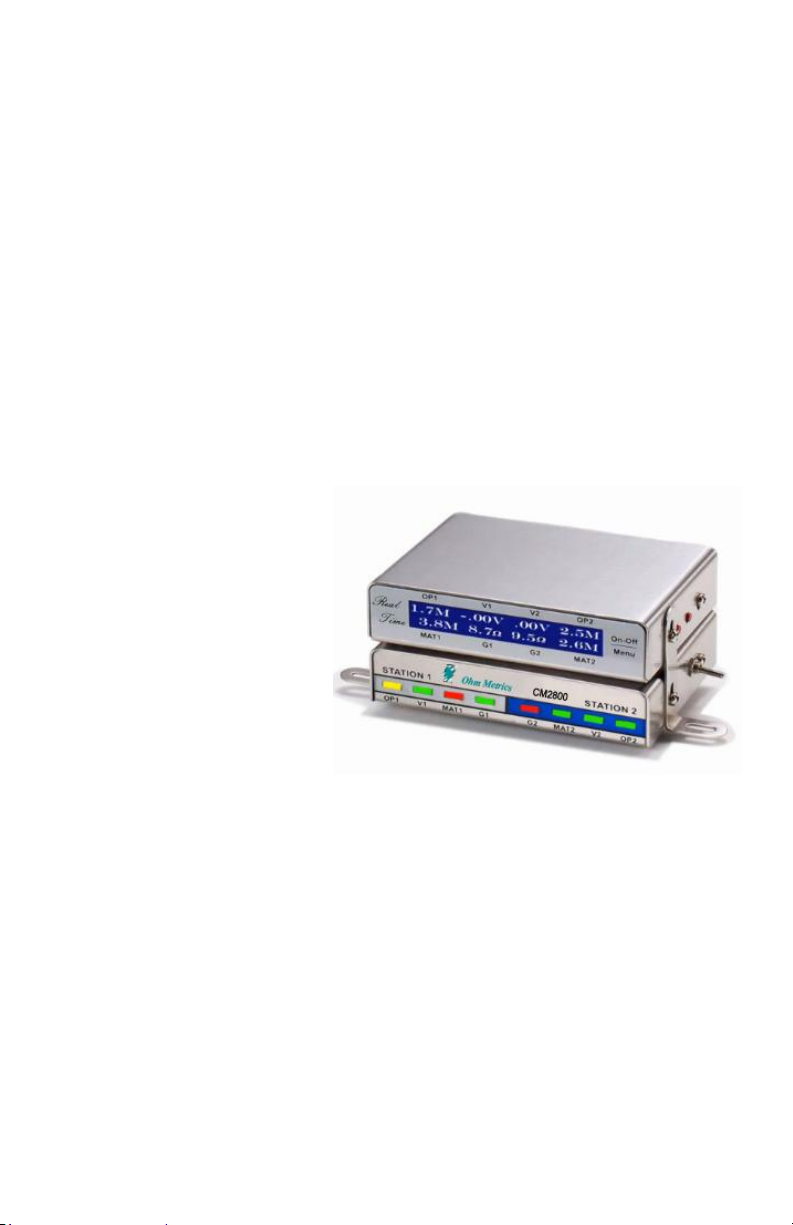
CM2800–D: Digital Display Unit.
CM2800-D is a digital dis-
play unit used with a
CM2800 ESD monitor. It
displays the values of the
results that CM2800
measures in a real-time
so that the users in the
field can observe the ac-
curate measurements of
the monitoring status.
Besides the digital meas-
urement values, the device can also show the current limit options and
other external interface control settings selected by the user. Using
external control interfaces located on the back of the device, the
CM2800 can attach the warning of each operator to an external siren.
Push the red “Menu” Button to enter the 1st page of the on-screen
menu. There are total of 8 pages. The display module will go back to
main screen if the menu screen is idle for more than 30 seconds. Dis-
plays “O” for monitored items, “X ” for disabled items.
CM2800 with the CM2800-D attached.
9
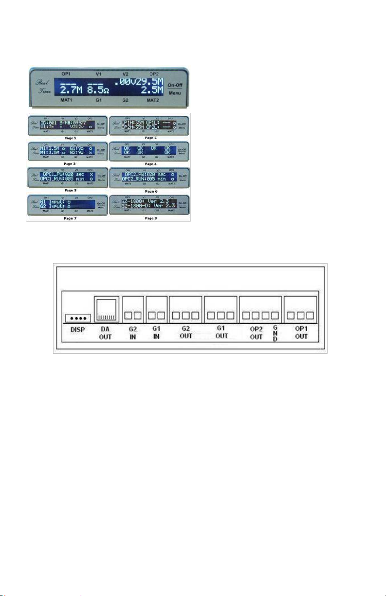
CM2800-D Display Screens
CM2800-D is connected to a CM2800 through the port “DISP”.
“OP1 OUT”: Dry-Contact relay output for OP1 alarm.
“OP2 OUT”: Dry-Contact relay output for OP2 alarm.
“GND”: DC power ground.
“G1 OUT”: Dry-Contact relay output for G1 alarm.
“G1 IN”: Open/Short input control from external device for G1.
Shorted input means the IN is active.
“G2 IN”: Open/Short input control from external device for G2.
Shorted input means the IN is active.
“DA OUT”: Digital/Analog Output. These signals are optional.
CM2800-D Back Panel
Main Screen: Display the real-time measure-
ment value of the resistance and voltage.
PAGE 1: CM2800’s ID number, S/N#, current
limit option and status for V1 & V2.
PAGE 2: Current High/Low limit option and
status of OP1&OP2.
PAGE 3: Current limit option and status of M1,
M2, G1 & G2.
PAGE 4: Real-time measurement results in “OK”
or “Err” for all monitored items of CM2800.
PAGE 5: Current limit option and status of OPC1.
PAGE 6: Current limit option and status of OPC2.
PAGE 7: Current control status of G1 & G2
PAGE 8: Hardware version of CM2800 &
CM2800-D.
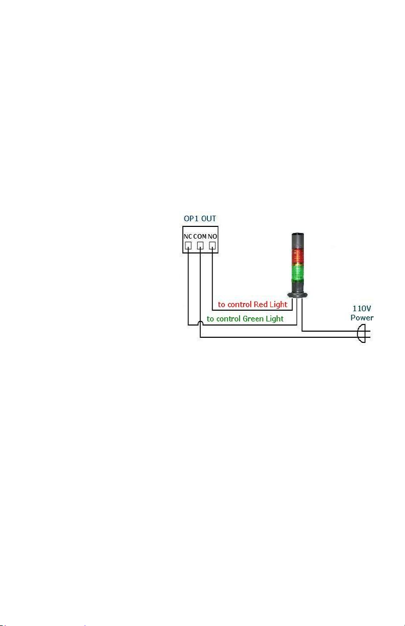
The “OP1 OUT” dry-contact relay is activated along with the moni-
toring status of OP1’s resistance and voltage. When OP1’s resis-
tance or voltage exceeds the preset limits, the corresponding built-
in dry contact relay will switch from NC to NO. Every relay has 3
contacts with the center contact as common contact, the left con-
tact as NC (Normally Close) and the right contact as NO (Normally
Open). Each of these relays has contact rating of 1A at 30VDC, 2A at
120VAC, and 3A at 24VDC.
The “OP2 OUT”, “G1 OUT” and “G2 OUT” can be activated in a way
similar to “OP1 OUT”.
These relay contacts can
be used to control the
external devices such as a
tower siren or other ac-
cess control devices. In
the connection diagram
on the right, we illustrate
how to utilize “OP1 OUT”
to control an external 110V Green/Red tower alarm.
(Note: You need to reserve 250mA power capacity for each
CM2800 with digital display module CM2800-D among the inter-
linked units that share the same DC power adaptor. For example, a
1A DC power adaptor will be required if you plan to let 4 sets of
CM2800 + CM2800-D share one DC power.) These monitors are
interlinked with a special 10-feet communication cable provided by
Transforming Technologies with the Part# of GZ-485CABLE.

11
CM2800 SEE - Hardware Management Program
The CM2800-SEE is a PC-based program that communicates to the
monitor through an RS-232 port and an RS-232/RS-485 converter.
All the CM2800 supported monitor functions can be re-configured
dynamically with a clear on-screen menu:
Enable/Disable operator resistance and voltage
measure
Set the limit of operator resistance and voltage
Enable/Disable ESD mat resistance
Set the limit of ESD mat resistance
Enable/Disable Tool/Equipment resistance
Set the limit of Tool/Equipment resistance
View the measured data in real-time
Set the monitor ID and Description
CM2800-H -CM2800 Network Router
CM2800-H is a dedicated network router to be used with a CM2800
dual wire ESD monitor. It has 4 connection ports each of which can
connect to a maximum of 32 CM2800 monitors. A maximum of 128
monitors can be connected to this Router. The Router contains an
RJ45 port that can connect to a LAN through TCP/IP. A special high
speed processing technique is used in the Router to pro-vide high
performance data processing and communication amongst net-
worked monitors and the host PC-based network management
software.
CM2800 IMS - Central Monitoring Software
The CM2800-IMS is a PC-based control program used to monitor a
network of CM2800 monitors. A host computer is transformed into
a command center with the CM2800-BOSS SEE, a central monitor-
ing program that shows real time grounding results and allows for
adjustment of alarm parameters of up to 4096 workstations. An
entire assembly line’s ESD protection can be remotely monitored
and adjusted with one computer.
For more information on the CM2800 accessories please contact
Transforming Technologies.
CM2800 SEE On Screen Menu

12
CM2800 Series Monitor Specifications
Wrist-strap resistance alarm limit: User programmable from
750KΩ~2.4MΩ resistance for “Low” wrist-strap alarm and
8MΩ~35MΩ resistance for “High” wrist-strap alarm.
Maximum wrist-strap operator voltage: 50 mV max with 10 M max
operator resistance, less than 100 mV under wrist strap open fault
conditions.
Operator Voltage Detection: User programmable to detect a voltage
on the operator relative to ground, from +/- 1 volt up to +/- 5 volts in
increment of 1 volt.
Mat (soft ground) resistance alarm limit: User programmable from
1MΩ to 140MΩ.
Maximum mat (soft ground) voltage: Less than 50 mV even under
fault conditions.
Tool (hard ground) resistance alarm limit: User programmable from 2Ω
resistance to 20Ω resistance.
Maximum tool (hard ground) voltage: Less than 50 mV even under fault
conditions.
Maximum tool (hard ground) current: Less than 0.2 mA.
Configurability: Every monitored parameter can be programmed by a PC-
based program to be enabled / disabled or to set the alarm limit to a spe-
cific threshold.
RJ-485 Socket IN/OUT Communication: Built-in RJ-485 IN and OUT com-
munication ports to support multiple units drop-line internetworking.
DC Power Supply: 7-15 VDC, 100mA.
AC Input: 100-240 VAC, 1A. (The excess current capacity is reserved for
multiple units interlinking.)
CM2800-D Technical Specification
Parameters Status: display ID# and S/N#, current high/low limits, moni-
tored item options selected, and current monitoring result for operator
resistance, operator voltage, mat resistance, tool resistance
Tool Control Status: display current status of external interface control
settings of G1 and G2
OPC Status: display current status and control limits
Display Control: mini Enable/Disable push button
LCD Display: 20 x 2 characters
DC Power Supply: 5VDC, 150mA
Dimensions: L: 4in W: 3in H: 1in

13
Service and Warranty
Transforming Technologies, LLC provides a limited warranty for the
CM2800 series. All new products are guaranteed to be free from
defects in material and workmanship for a period of one (1) year
from the date of shipment. Liability is limited to servicing (after
evaluating, repairing or replacing) any product returned to Trans-
forming Technologies. The company does not warrant damage due
to misuse, neglect, alteration or accident. In no event shall Trans-
forming Technologies be liable for collateral or consequential dam-
ages. NOTE: Wrist strap remotes terminal boxes are subject to me-
chanical wearing and considered to be “consumable items”. They
have separate warranty of 6 months.
To receive service under warranty, please contact Transforming
Technologies Technical Support.
About Transforming Technologies
Since 1998, Transforming Technologies, has provided critical solu-
tions to the numerous manufacturing problems associated with
static electricity. Transforming Technologies offers a wide range of
unique and outstanding products to detect, protect, eliminate and
monitor electrostatic charges. Our products are integral compo-
nents of an effective static control program.

14
Phone: 419-841-9552
Fax: 419-841-3241
E-mail: info@transforming-technologies.com
3719 King Rd.
Toledo, Ohio 43617
T r a n s f o r m i n g T e c h n o l o g i e s , L L C
Table of contents
Other Transforming Technologies Measuring Instrument manuals

Transforming Technologies
Transforming Technologies Ohm Metrics SRM 310 User manual

Transforming Technologies
Transforming Technologies Ohm Metries SRM320 User manual

Transforming Technologies
Transforming Technologies Ohm Metrics EFM115 User manual

Transforming Technologies
Transforming Technologies GTS600 User manual

Transforming Technologies
Transforming Technologies OhmMETRICS EFM250 User manual

Transforming Technologies
Transforming Technologies WST 200 User manual

Transforming Technologies
Transforming Technologies Ohm Metrics SRM330 User manual


