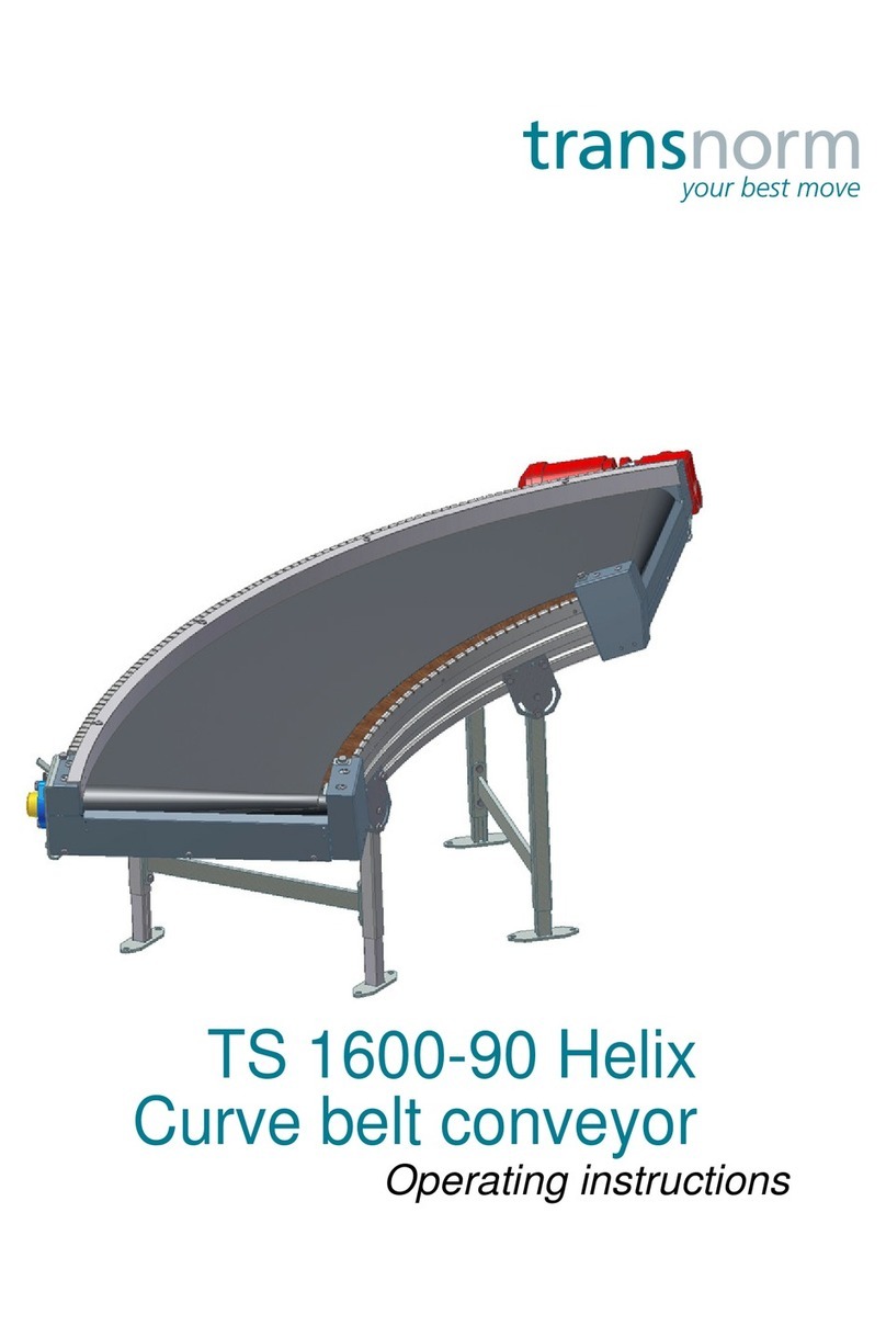
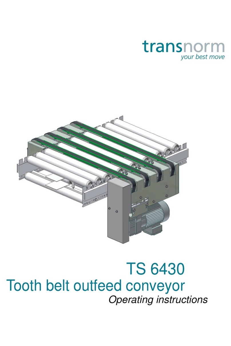
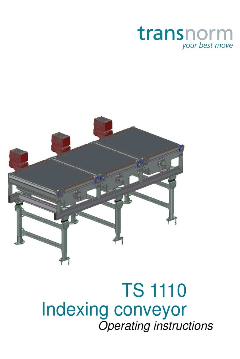
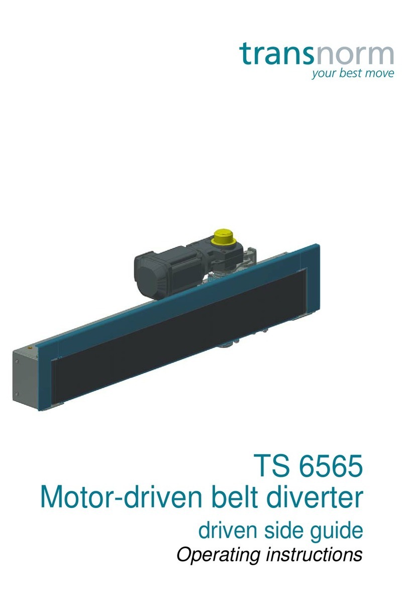
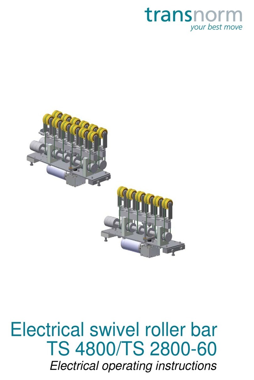
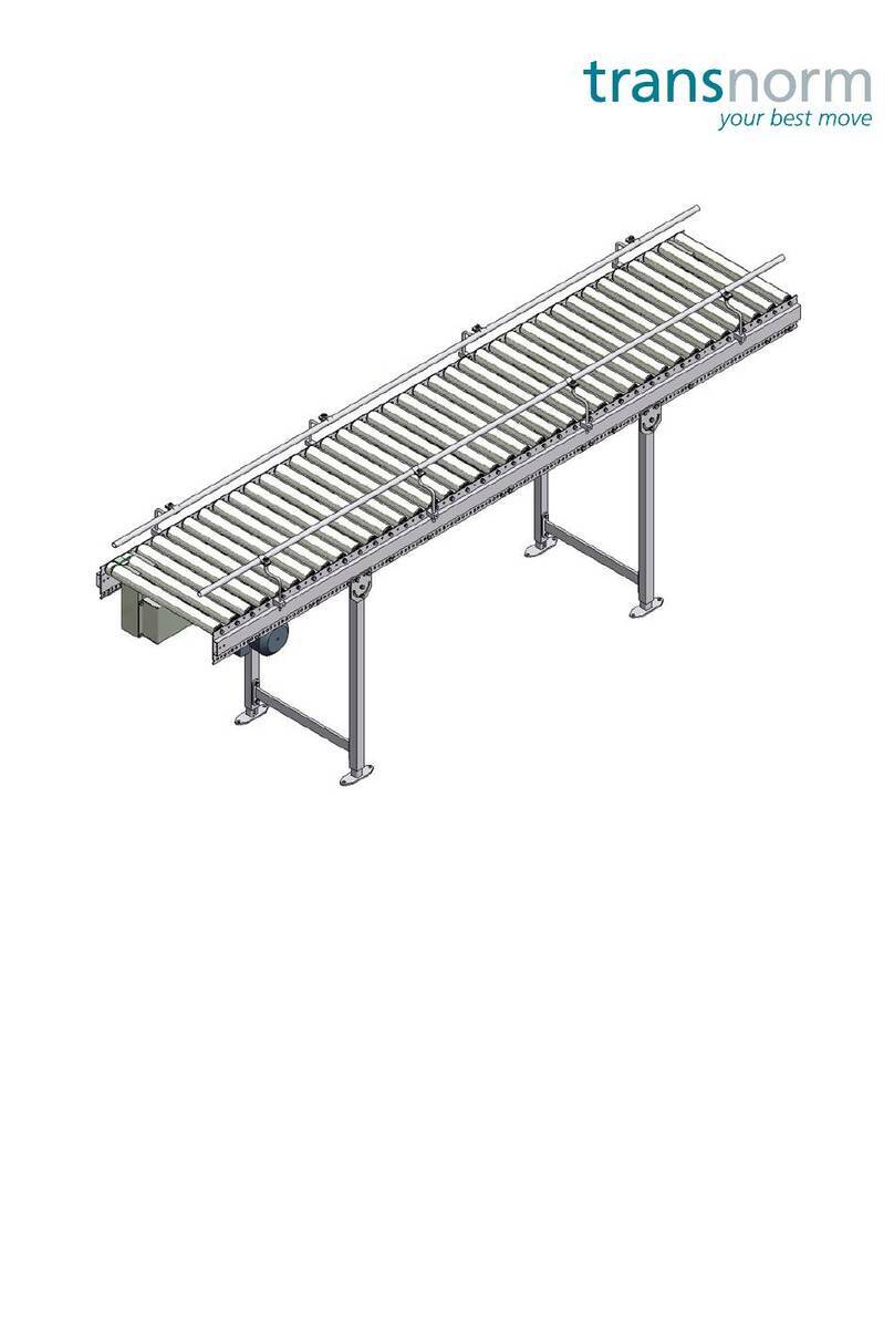
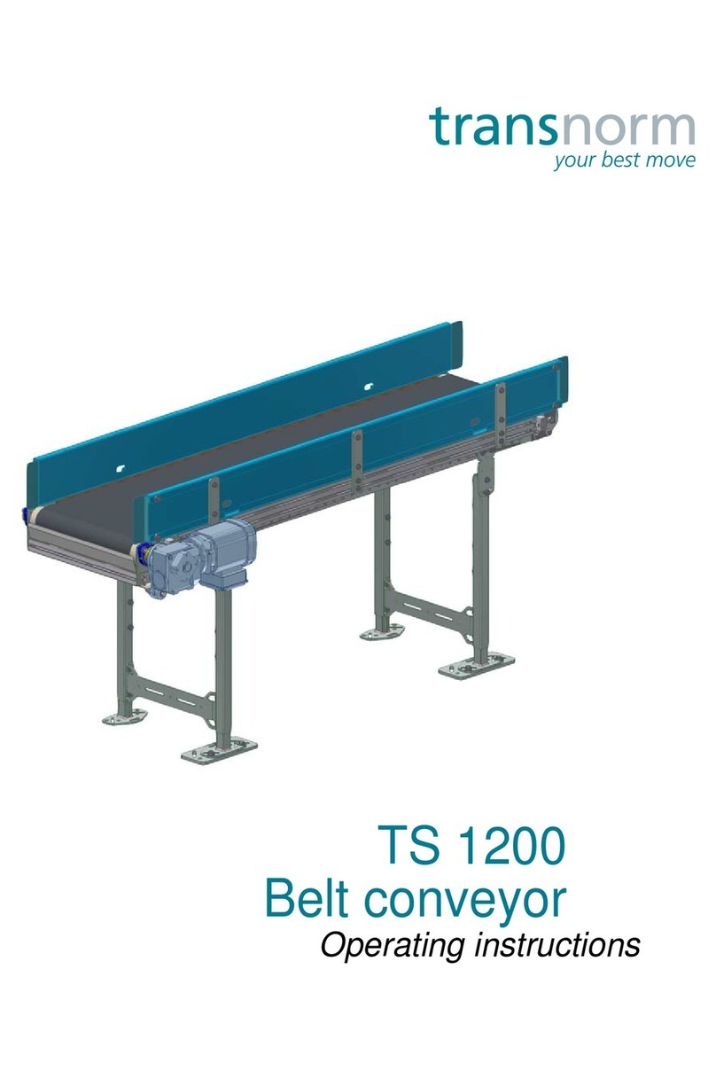
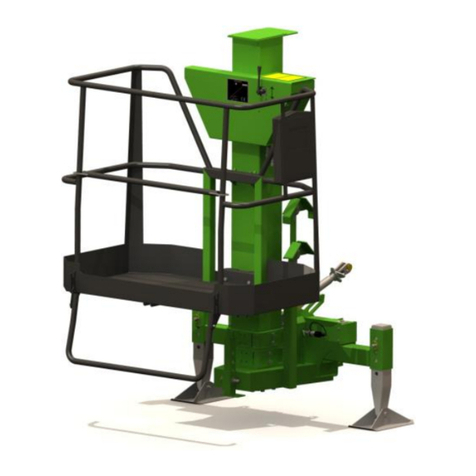
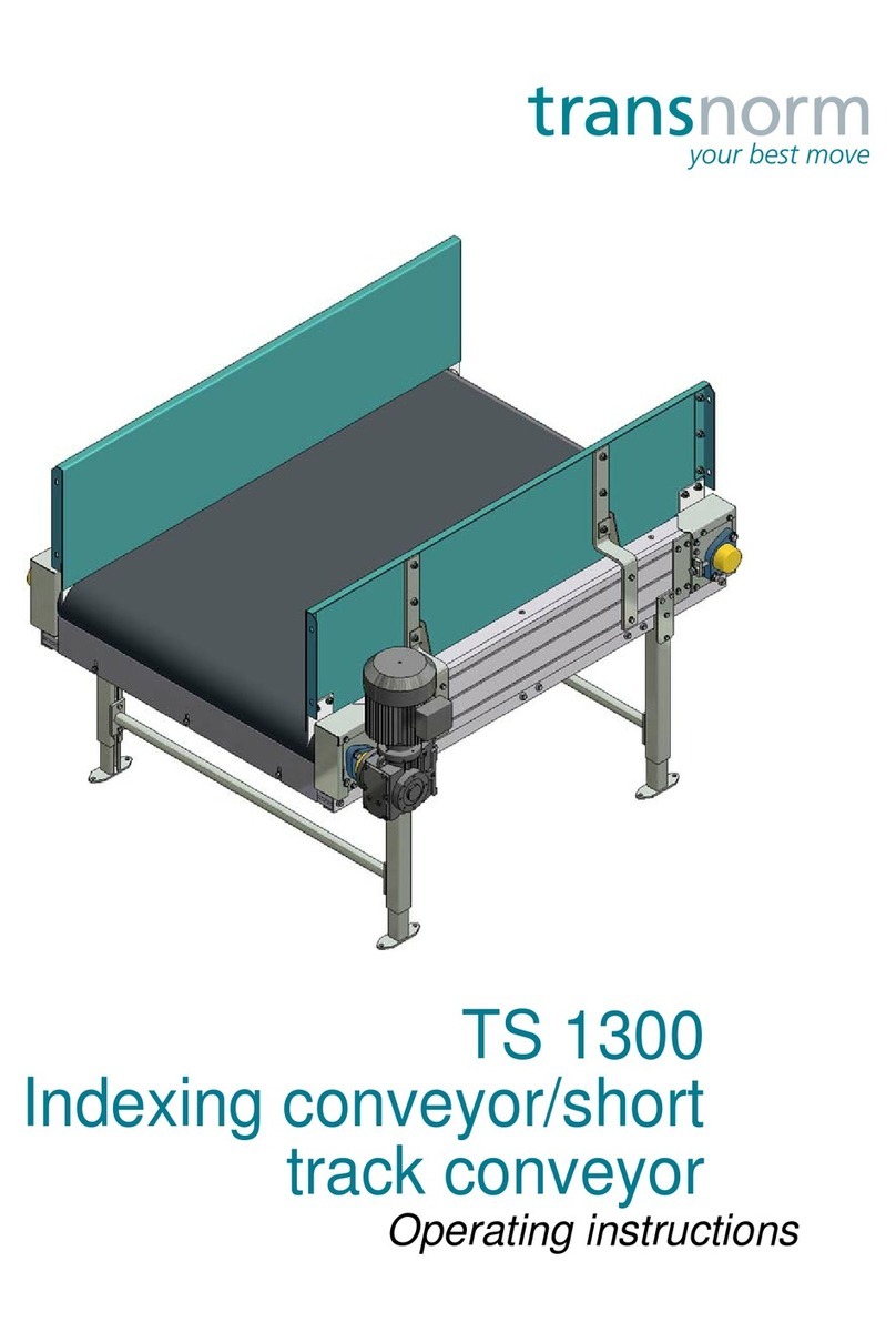
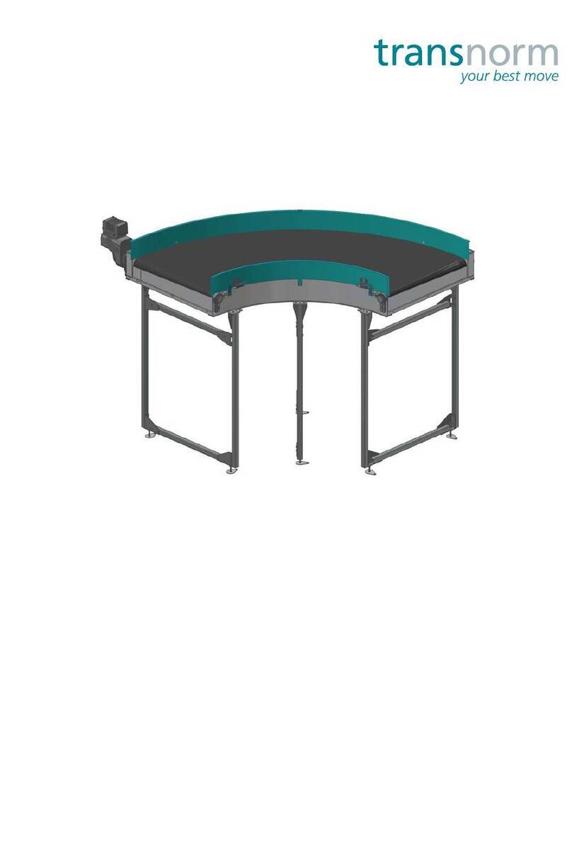
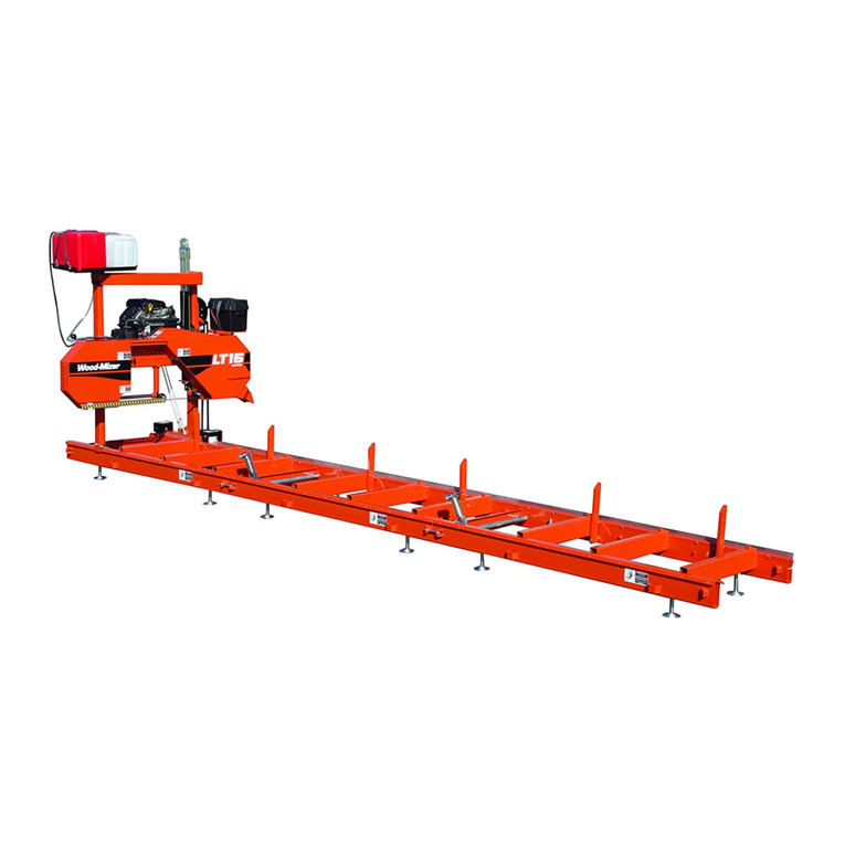
transnorm TS 4800 User manual

TS 4800
Outfeed conveyor
Operating instructions

2
Operating instructions: Outfeed conveyor TS 4800
Version 3.6ENG, 27.01.2020
Product Outfeed conveyor TS 4800
Manufacturer TRANSNORM SYSTEM GmbH
Förster Str. 2
D-31177 Harsum
Tel. +49 (0) 5127 4020
Fax +49 (0) 5127 4400
http://www.transnorm.com
Documentation Operating instructions, -TRANSLATION-
Version 3.6 ENG, 27.01.2020
Subject to modifications. All rights reserved by TRANSNORM SYSTEM
GmbH. Reprint and reproduction only with written approval.
Revision V 2.0 Completely revised edition
V 2.1 Technical data revised
V 2.2 Description revised
V 2.3 Maintenance and repair revised
V 2.4 Maintenance and repair revised
V 2.5 Drive belt replacement revised
V 2.6 Description, safety and maintenance and repair revised
V 2.7 Electric swivel roller bars added and description/maintenance
schedule revised
V 2.8 Remaining risks and safety instructions revised
V 2.9 Introduction and safety revised
V 3.0 Maintenance schedule and troubleshooting revised
V 3.1 Technical data, maintenance schedule and troubleshooting revised
V 3.2 Maintenance and repair revised
V 3.3 Maintenance and repair revised
V 3.4 Separation of the TS 4800 with electric swivel roller bars to sepa-
rate operating manual
V 3.5 Technical description revised
V 3.6 Replace swivel roller bar, alternative method added

Table of contents 3
Table of contents
Applicable documents................................................................................................................ 7
EC Declaration of Incorporation ........................................................................................................... 7
Introduction .................................................................................................................................... 9
Purpose of the document ..................................................................................................................... 9
Validity ............................................................................................................................................ 9
Illustrations ..................................................................................................................................... 9
Using the instructions ......................................................................................................................... 10
Safety instructions .............................................................................................................................. 11
Copyright Protection ........................................................................................................................... 12
Service................................................................................................................................................ 12
Warranty ............................................................................................................................................. 13
Safety............................................................................................................................................... 15
Operating conditions........................................................................................................................... 15
Intended use................................................................................................................................. 15
Impermissible operating conditions ..............................................................................................16
Responsibilities of the Operating Company / Integrator............................................................... 16
Protective devices .............................................................................................................................. 18
Maintenance unit ................................................................................................................................ 20
Staff qualifications .............................................................................................................................. 21
Remaining risks regarding the machine ............................................................................................. 22
Remaining risks for operating personnel...................................................................................... 22
Remaining risks for technical personnel....................................................................................... 24
Description.................................................................................................................................... 27
Technical description .......................................................................................................................... 27
Main dimensions................................................................................................................................. 28
Conveyor configurations..................................................................................................................... 29
Technical data..................................................................................................................................... 29
Machine areas .................................................................................................................................... 31
Parts of the machine........................................................................................................................... 32
Optional machine equipment.............................................................................................................. 33
Transportation and erection................................................................................................... 35
Delivery of the machine ...................................................................................................................... 35
Unpacking the machine................................................................................................................ 35
A longer storage period of the machine........................................................................................ 35
Disposing of packaging material .................................................................................................. 36
Setting up the machine....................................................................................................................... 36
Ground requirements ................................................................................................................... 36
Tolerable operating conditions...................................................................................................... 36

Table of contents4
Operating instructions: Outfeed conveyor TS 4800
Version 3.6ENG, 27.01.2020
In-company transportation..................................................................................................................37
Auxiliary equipment ......................................................................................................................38
Transport with industrial truck or crane...............................................................................................40
Final assembly on site ........................................................................................................................41
Installation ....................................................................................................................................41
To carry out the assembly.............................................................................................................42
Electrical connection.....................................................................................................................45
Pneumatic block diagram ...................................................................................................................46
Operation .......................................................................................................................................49
Commissioning ...................................................................................................................................49
Commissioning and start-up after service and maintenance works ...................................................49
Normal operation ................................................................................................................................52
Shutdown............................................................................................................................................52
Maintenance and care...............................................................................................................53
Maintenance works.............................................................................................................................53
Motor maintenance.......................................................................................................................53
Gear unit maintenance .................................................................................................................53
Lubricants ...........................................................................................................................................54
Maintenance plan ...............................................................................................................................54
Cleaning and care...............................................................................................................................56
Maintenance and repair............................................................................................................57
Spare part purchasing ........................................................................................................................57
Tools, equipment and supplies ...........................................................................................................57
Tightening torques ..............................................................................................................................58
Guards ................................................................................................................................................59
Replacing the tubular side guide ........................................................................................................60
Replacing the idler rollers ...................................................................................................................61
Replacing the tail pulley......................................................................................................................62
Replacing the finger guard..................................................................................................................63
Replacing the pressure roller..............................................................................................................64
Replacing the drive belt ......................................................................................................................65
Drive belt, non-endless joint .........................................................................................................65
Drive belt, endless joint ................................................................................................................67
Loosening/tensioning/adjusting the drive belt.....................................................................................71
Tensioning unit..............................................................................................................................71
Tail pulley......................................................................................................................................74
Replacing the gear motor ...................................................................................................................77
Gear motor, motor position M3 .....................................................................................................77
Shaft-mounted worm gear ............................................................................................................81
Replacing the swivel roller assembly..................................................................................................83
Servicing the swivel roller assembly ...................................................................................................87
Pneumatic block diagrams..................................................................................................................94

Table of contents 5
Fault clearance ............................................................................................................................ 97
What to do if... .................................................................................................................................... 97
Motor and gear unit ............................................................................................................................ 98
Decommissioning and waste disposal.............................................................................. 99
Machine disposal................................................................................................................................ 99
Main components of the machine..................................................................................................... 100
Contact details........................................................................................................................... 101
Head office ....................................................................................................................................... 101
Subsidiaries, branch offices and sales partners worldwide .............................................................. 102
Service branches - Germany............................................................................................................ 104
Suggestions and information ............................................................................................................ 104

Table of contents6
Operating instructions: Outfeed conveyor TS 4800
Version 3.6ENG, 27.01.2020

Applicable documents
EC Declaration of Incorporation 7
Applicable documents
EC Declaration of Incorporation

Applicable documents
EC Declaration of Incorporation
8
Operating instructions: Outfeed conveyor TS 4800
Version 3.6ENG, 27.01.2020

Introduction
Purpose of the document 9
Introduction
Purpose of the document
These operating instructions enable you to safely operate the delivered
machine, defined as partly completed machinery by the EC Machinery Direc-
tive, in accordance with its intended use.
Read through these instructions carefully before commissioning the
machine. For further technical information, please refer to the order confir-
mation supplied separately.
You will find information on the following topics in the sections below:
The safe handling of the machine
Technical specifications
Transporting, installing and putting the machine into operation
Maintenance instructions
Repairing the machine
Fault detection and correction
Taking the machine out of operation and disposal
Validity
These operating instructions apply to the operating company/integrator and
all persons working on or with the machine.
Illustrations
The illustrations show simplified views of the machine.
We reserve the right to carry out technical alterations in case of further
developments. If assembly is not described, it will be carried out in exactly
the opposite order to disassembly.
Due to the numerous possible system configurations of our machines,
details shown in the illustrations may differ from the machine supplied.
See the order confirmation for an exact description
of your specific machine.

Introduction
Using the instructions
10
Operating instructions: Outfeed conveyor TS 4800
Version 3.6ENG, 27.01.2020
Using the instructions
Different circumstances are indicated using specific text/formulations. Impor-
tant information has also been marked with additional symbols. The following
is an overview of the different ways information is formulated.
This is a single, complete step.
1. This is the first step in a series of actions.
This is a useful remark on a specific step.
?This is a problem that may arise.
This is the cause of the problem.
This is a measure to solve the problem.
You have completed a series of actions.
You have completed the entire activity.
This is a notice.
Notices provide additional information.

Introduction
Safety instructions 11
Safety instructions
Safety instructions warn of risks and remaining risks and offer information on
how to prevent them.
The signal words CAUTION, WARNING and DANGER indicate the level of
severity of the risk.
The following overview explains the safety instructions used in this docu-
ment.
DANGER
This notice warns of risk of death or fatal injury
This states the cause of the danger.
You must take this action to avert the danger.
WARNING
This notice warns of moderate or minor injury
This states the cause of the danger.
You must take this action to avert the danger.
CAUTION
This notice warns of damage to materials or to the machine
This states the cause of the danger.
You must take this action to avert the danger.

Introduction
Copyright Protection
12
Operating instructions: Outfeed conveyor TS 4800
Version 3.6ENG, 27.01.2020
Copyright Protection
This publication must be treated as strictly confidential. It is intended only for
internal use by an authorised group of persons. and must not be disclosed to
third parties without the written approval of TRANSNORM SYSTEM GmbH.
All documents are protected within the meaning of the Copyright Protection
Act. The transfer and duplication of documents, also by way of extract, is
strictly prohibited. Non-compliance shall be prosecuted and subject to the
payment of compensation.
Service
Our service is available for technical information on our products and their
systematic application.
Please have the following information ready when contacting us with queries
or spare parts orders:
Machine type
Order/project number
Item number
You will find this information on the type identification plate of your machine.
It is located in the vicinity of the drive unit.
TRANSNORM SYSTEM GmbH type identification plate, sample
You will find our contact data at the back of these operating instructions.

Introduction
Warranty 13
Warranty
We shall accept no responsibility for any defects or damage caused by inap-
propriate use, operating errors or incorrect servicing and maintenance. We
expressly point out that only original spare parts and
accessories approved by TRANSNORM SYSTEM GmbH may be used.
Unless otherwise stipulated in the contract, the warranty period begins on
the day of delivery or with notification of readiness to deliver.
Please file all claims under warranty immediately upon identifying the
defect/s. Please quote the order (project) and item number when making a
claim.
The warranty shall be in line with statutory regulations. Further claims are
excluded.
Please note that the warranty shall be rendered null and void in the case of:
Use not in accordance with the intended purpose
Improper connecting and preparatory work not included within our scope
of service
Improper use of controls
Failure to use original spare parts and accessories
Conversions or structural modifications which have not been authorised
by us in writing
Wearing parts are generally excluded from the terms of warranty
.

Introduction
Warranty
14
Operating instructions: Outfeed conveyor TS 4800
Version 3.6ENG, 27.01.2020

Safety
Operating conditions 15
Safety
Operating conditions
The conveyor, subsequently referred to as the machine, is an incomplete
machine as defined by the EC Machinery Directive. The machine has been
designed according to the state of the art.
Nevertheless, there may be dangers arising from the machine under the
following circumstances:
Improper use
Improper application
Impermissible operating conditions
Failure to comply with these installation and operating instructions
Failure to comply with the general safety regulations during transport and
installation
Intended use
The machine shown on the front page is designed exclusively for the trans-
port of unit loads in compliance with the contract specifications and is
intended for incorporation into a fully automatic intralogistic system with
superordinate control.
Any use other than this is classed as improper use and is forbidden.
We point out explicitly that the machine is not designed for transporting
human beings.
It may only be used in a protected industrial environment with restricted
access.
The manufacturer accepts no liability for damage arising from improper use
of the machine.

Safety
Operating conditions
16
Operating instructions: Outfeed conveyor TS 4800
Version 3.6ENG, 27.01.2020
Impermissible operating conditions
Operation of the machine is prohibited under the following circumstances:
There are people or objects in the hazardous areas
Safety devices are not working or have been removed
The machine is malfunctioning or damaged
Maintenance intervals have been exceeded
Operating parameters have been changed without authorisation
Responsibilities of the Operating Company / Integrator
The machine safety can only be guaranteed if all required measures are
taken. The operating company/integrator is responsible for planning and
implementing appropriate measures.
These operating instructions are part of the machine. You are obligated to
pass on this document to the buyer of the machine should it be sold.
The operating company/integrator of the machine is responsible for its
safety. This applies especially to:
The installation to form a complete machine with functioning and
compliant safety devices.
The incorporation of the machine in such a way that no additional
danger/hazards are created.
Protection of the life and limb of all personnel working on or at the
machine.
Fault-free operation of the machine.
Minimising the danger of injury
Take steps to guarantee the safety of persons in the vicinity of the machine,
for example:
Ensure that all work on the machine is carried out by qualified and
authorised personnel.
Make sure all operators are familiar with the safety devices.
Ensure that personnel keep the machine and its surroundings clean and
orderly at all times.
Provide safety equipment for operating personnel. Make sure the protec-
tive clothing is worn.
Provide instructions on how to proceed and behave in case of accidents
and emergencies.
Clarify questions on occupational health and safety and protection of the
environment.

Safety
Operating conditions 17
Operating the machine trouble-free
Implement the following measures to ensure trouble-free operation of the
machine:
Ensure that the operating instructions are complete, in legible condition
and accessible to all personnel at all times.
Only operate the machine when fully functional.
Routinely check the operability of the machine and the safety equipment.
Carrying out Installation Layout
Observe the following basic safety principles when connecting several sepa-
rate components to form an overall system:
Install isolating safety devices in areas of pulleys, apex bends, roller
arches, conveyor gates and transfer drives.
In the vicinity of a transfer drive or a conveyor gate, the belt must have
the same speed or run faster in the outfeed area than in the infeed area.
The national safety regulations valid in the country of use as well as
additional sector-specific requirements shall apply.
Commissioning
This conveyor system is a "partly completed" machinery, as defined by the
Machinery Directive 2006/42/EC,Article 2g. Only the use of a respective
control system and if necessary other (partly completed) machinery allows
for intralogistic functionality. It must not be commissioned until it has been
ascertained that the partly completed machinery which is the subject of this
documentation or the machinery into which it is incorporated comply with the
requirements of the Machinery Directive.

Safety
Protective devices
18
Operating instructions: Outfeed conveyor TS 4800
Version 3.6ENG, 27.01.2020
Protective devices
Various covers are installed on the machine to prevent limbs being drawn in
and crushed. The protective devices and safety equipment are listed in the
following.
It is expressly prohibited to render unserviceable, bypass or remove protec-
tive devices. These devices may only be temporarily removed for mainte-
nance or repair purposes. If the purchasing contract specifies that certain
safety equipment is not included in the scope of delivery, the operating
company/integrator must assess the potential dangers in accordance with
the Machinery Directive. If it proves to be necessary to install additional
guards, especially at the infeed and transfer points, they must be installed in
accordance with applicable national regulations and guidelines.
With the machine suspended from the ceiling, safety devices, which prevent
the risk posed by falling parts, must be installed in accordance with valid
national regulations and guidelines.
Refer to the maintenance schedule for information on inspection intervals.
Overview of the protective devices
1
2
3

Safety
Protective devices 19
Safety equipment on the TS 4800
Item Description
1Bottom cover
2Front cover
3Finger guard

Safety
Maintenance unit
20
Operating instructions: Outfeed conveyor TS 4800
Version 3.6ENG, 27.01.2020
Maintenance unit
The maintenance unit comprises four components: the manual start-up
valve, the filter regulator, a soft start/quick exhaust valve and a branching
module. The start-up valve and the soft start/quick exhaust valve are
provided with a silencer for the exhaust air.
The lockable rotary knob enables to lock the preset pressure. This allows to
ensure that only technical personnel puts the valve into operation again after
a malfunction has occurred or during maintenance works.
The maintenance unit enables to ventilate the system under control for main-
tenance and service tasks when a malfunction has occurred or for mainte-
nance works.
The maintenance unit meets the performance level C according to DIN EN
ISO 13849-1.
Maintenance unit, example illustration
Picture illustration
Item Description
1manual start-up valve
2filter regulator
3soft start/quick exhaust valve
4branching module
1
23
4
Other manuals for TS 4800
1
Table of contents
Other transnorm Industrial Equipment manuals

transnorm
transnorm TS 6565 User manual

transnorm
transnorm TS 6430 User manual

transnorm
transnorm TS 2111 User manual

transnorm
transnorm TS 4800 User manual

transnorm
transnorm TS 1600-90 Helix User manual

transnorm
transnorm TS 1600-140 SP User manual

transnorm
transnorm TS 1600-105FH2 User manual

transnorm
transnorm TS 1300 User manual

transnorm
transnorm TS 2920 User manual

transnorm
transnorm TS 2733 User manual