Traulsen G-Series User manual
MASTER SERVICE MANUAL
For All Full Size Undercounter, G-Series and R&A
Refrigerator, Freezer, Dual-Temp and Hot Food
Units
Traulsen
4401 Blue Mound Road Fort Worth, Texas
76106 Phone: (800) - 825 - 8220
Part Number 375-60351-00 Form Number TR36015 revised 3/17
1
Introduction
Traulsen provides this manual as an aid to the service technician in installation, operation and
maintenance of Traulsen units from year 2010 to present. When used properly. This service manual can
help the service technician maintain, troubleshoot and diagnose most of the problems and malfunctions
that may occur with the controllers. While we believe that most aspects of the controllers are covered in
this manual should you encounter a condition not addressed, or require a wiring diagram please
contact.
ITW Refrigeration
Traulsen
4401 Blue Mound Road Fort Worth, TX 76106
Attn: Service Department
Phone: (800) 825-8220
Fax: (817) 740-6757
To improve your service communication experience be sure to have the following available when
contacting technical support:
✓Serial number
✓Model number
✓A detailed explanation of the problem.
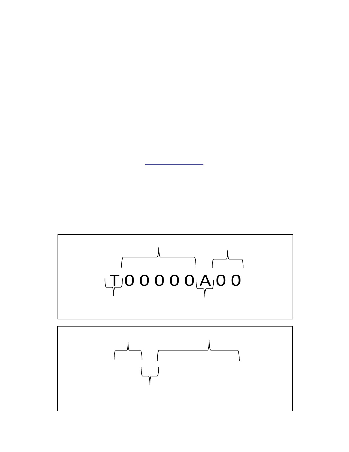
How to Read a Traulsen Serial Number
T FOR TRAULSEN
INDICATES WHERE BUILT
ALL SERIALS START WITH T OR V
MANUFACTURE MONTH CODE
A=JANUARY; B=FEBUARY; C=MARCH……..
LAST 2 DIGITS OF MANUFACTURE YEAR
UNIQUE SERIAL CODE
MANUFACTURE MONTH CODE
A=JANUARY; B=FEBUARY; C=MARCH……..
FIRST 2 DIGITS OF MANUFACTURE YEAR
UNIQUE SERIAL CODE
1 7 A 0 0 0 0 0 0

2
TABLE OF CONTENTS
Section I
Intela-Traul Control System
Page
a.
Intela-Traul Control System Overview
4
b.
Intela-Traul Alarm Codes from 2010 to present
5
c.
Control Access & Programming
6
d.
Troubleshooting Traulsen Intela-Traul Sensors
7
e.
Troubleshooting Traulsen Intela-Traul MIT II relay module
10
f.
RH Sensor Module
12
Section II
Refrigeration System
a.
Troubleshooting Traulsen Refrigeration System
14
b.
TXV Troubleshooting
15
c.
Troubleshooting a Frozen Evaporator Coil
16
d.
Compressor Troubleshooting
17
Section III
Compact & Milk Cooler Controls
a.
Danfoss Control Electronic Controller
20
b.
Danfoss Control Sensors
21
c.
Milk Cooler Temperature Checklist
22
Section IV
Preventive Maintenance
a.
Preventive Maintenance
24
Section V
Door Frame Heaters
a.
Door Frame Heater installation
27
b.
Door Frame Heaters in Roll-In units
30
c.
Door Frame Heaters in Half Height units
31
Section VI
Wiring Diagrams
a.
G & R/A Series
33
b.
UHT Danfoss Series
34
c.
ULT Danfoss Series
35
d.
Milk Cooler Danfoss Series
36
Section VII
G-Series Control (Blue Display)
a.
Control Overview
38
b.
Control Programing
39
c.
Display Errors
44
d.
Control Board Detail
45
Section VII
R/A-Series Control (Green Display)
a.
Control Overview
48
b.
Control Programing
49
c.
Control Board Detail
54

3
Section I
Intela-Traul Control System
4
I. a –Intela-Traul Control System Overview
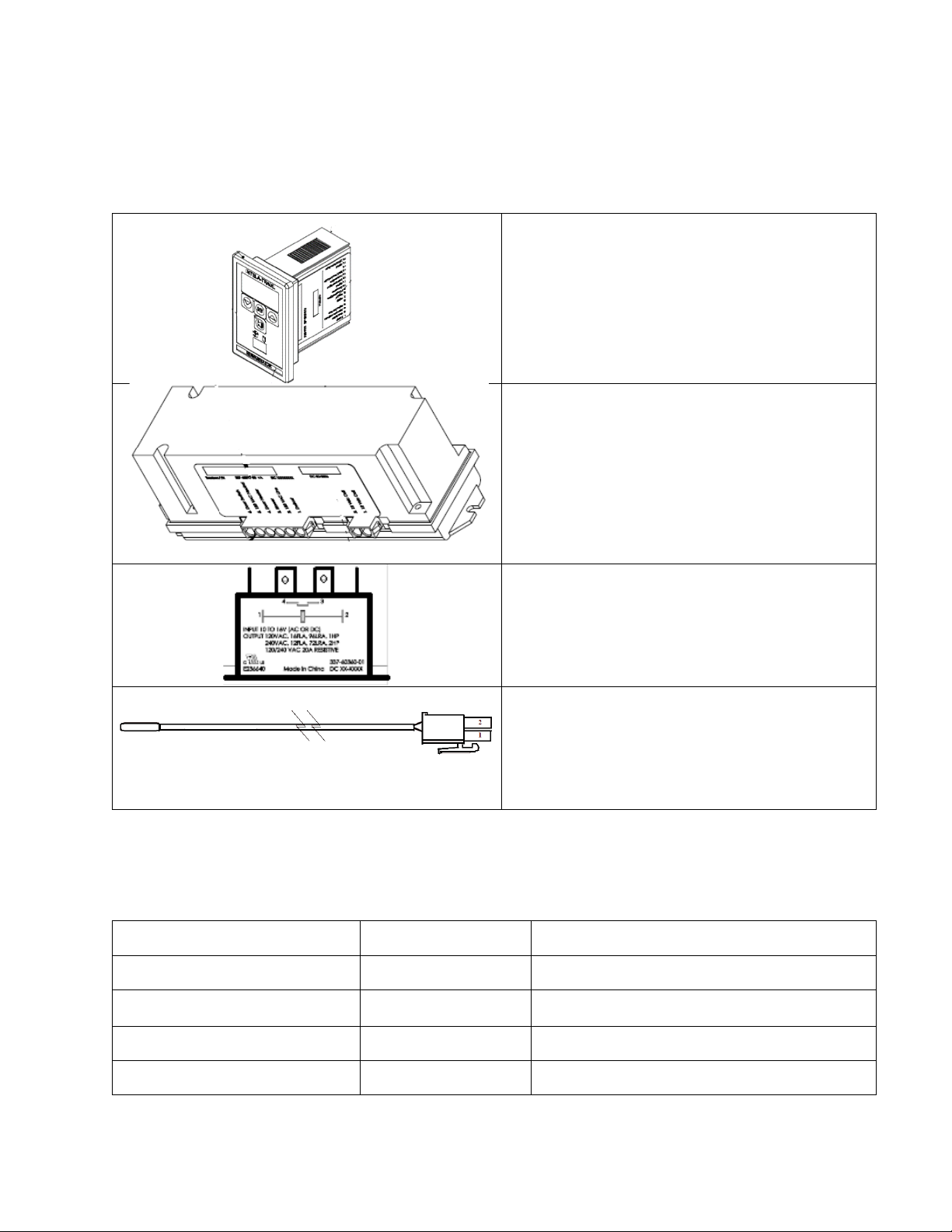
Intela-Traul Components:
Component
Description
Control Head
•Microprocessor Control
•User Interface
Relay Module
•DC Power Supply
•Blower Relay
•Defrost Heater Relay
•Door Frame Heater Relay
•Supplies 12VDC to Compressor Relay
Hybrid Relay
•Hybrid Solid State Relay
•Compressor/Condenser Relay
•12VDC Coil Voltage
Sensors
•Green –Cabinet Air
•Blue –Evaporator Coil
•Yellow –Liquid Line
Table 1
Basic Control Function:
Function
Component
Trigger
Cycles Door Frame Heaters
Door Frame Heaters
Based on Control Settings (will vary)
Cycles Evaporator Blower Motor
Evaporator Blower
Based on Control Settings (will vary)
Controls Defrost Cycle
Defrost Heater
Time Initiated, Terminated by Blue Evap Coil
Sensor Temp
Cycles Refrigeration System
Refrigeration System
Green Cabinet Air Sensor Temp
Triggers Alarm/Trouble Code
Alarms
Based on Control Settings
Table 2
5
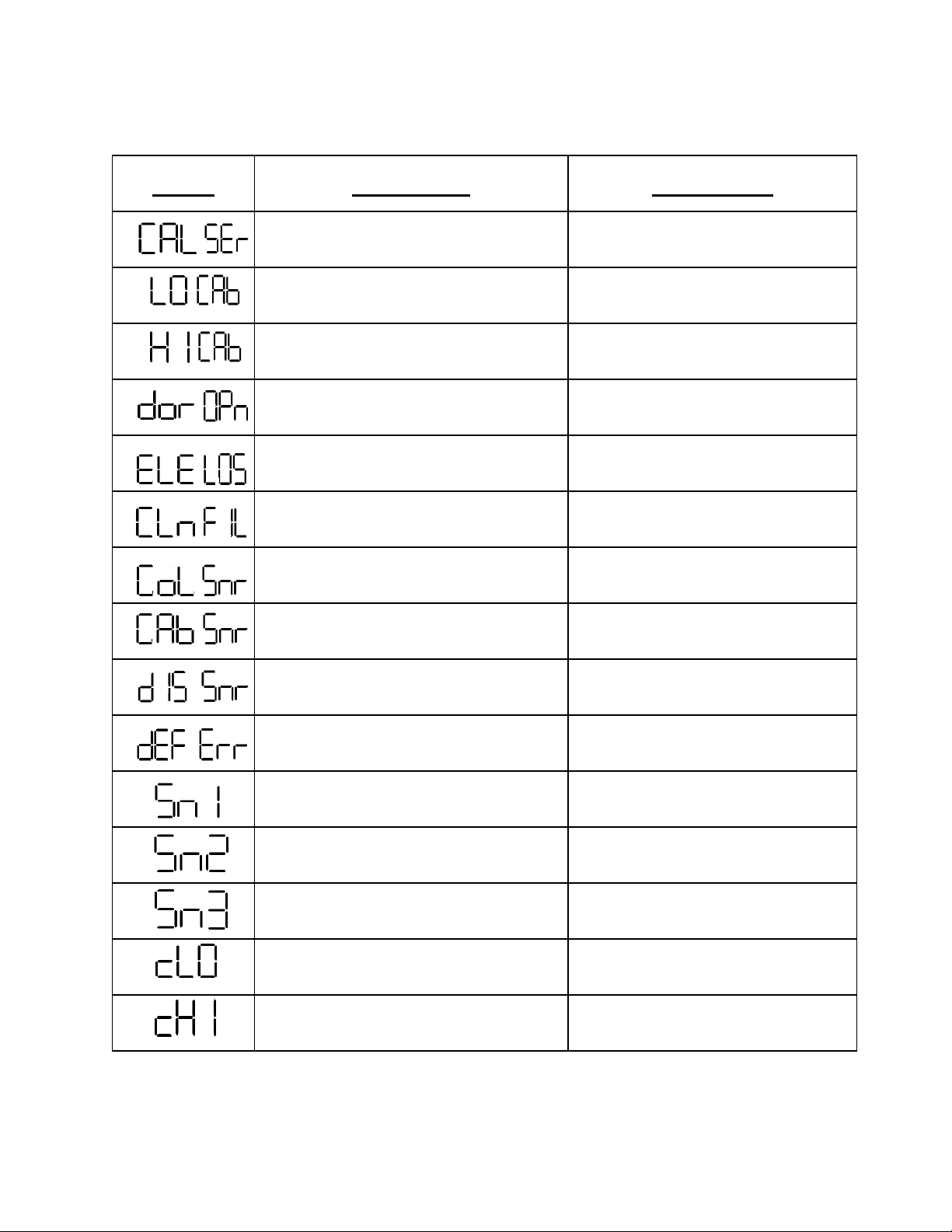
I. b - Intela-Traul Alarm Codes from 2010 to present
Alarm
Description
Clear Alarm
Refrigeration System Low Charge
Repair Refrigeration System
Low Cabinet Temperature Alarm
Return Cabinet Temperature to
Normal Range
High Cabinet Temperature Alarm
Return Cabinet Temperature to
Normal Range
Door Open Alarm
Close Door
Power Loss Alarm
Press Alarm Cancel
Clean Condenser Alarm
Clear/Clean Condenser Coil
Coil Sensor Open or Shorted
Replace Coil Sensor
Cab Sensor Open or Shorted
Replace Cabinet Sensor
Discharge Line Sensor
open or shorted
Replace Discharge Line Sensor
Defrost Terminates by Time, Not
Temperature, for 72 hours.
Troubleshoot Defrost Cycle
Cab Sensor Open or Shorted
Replace Cabinet Sensor
Coil Sensor Open or Shorted
Replace Coil Sensor
Liquid Line Sensor Open or Shorted
Replace Liquid Line Sensor
Low Cabinet Temperature Alarm
Return Cabinet Temperature to
Normal Range
High Cabinet Temperature Alarm
Return Cabinet Temperature to
Normal Range
Table 3
6
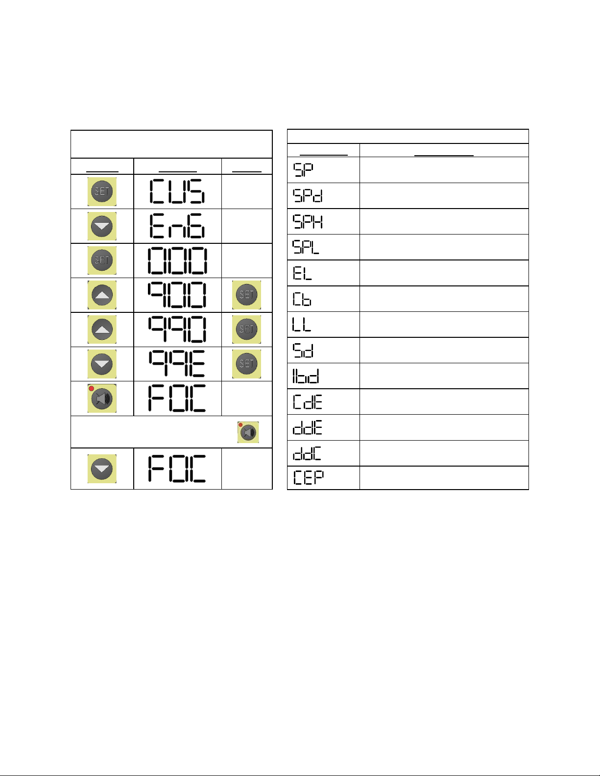
I. c –Intela-Traul Control Access & Parameters
To access the engineering/service menu follow the instruction below. As seen in Figures 1 & 2.
Figure 1
INTELA-TRAUL Access
Press
Display
Press
If control does not have
INTELA-TRAUL Key Parameters
Parameter
Description
Set Point
Set Point Differential
Set Point High
(Equip Prior to 2010 only)
Set Point Low
(Equip Prior to 2010 only)
Evaporator Coil Sensor Temp
Cabinet Air Sensor Temp
Liquid Line Sensor Temp
Start Manual Defrost
Intervals Between Defrost
(In hours)
Defrost Termination
Temperature
Drip Time After Defrost
Length of Defrost (In Minutes)
Reset to Factory Defaults
SET
SET
SET
SET
SET
Figure 2
7
I. d - Troubleshooting Traulsen Intela-Traul Sensors
Sensor Function:
•Cabinet Sensor (Green): The Cabinet sensor reads the temperature of the return air
and relays that value back to the control head. The control head either cycles the
compressor on or off depending on the temperature set points. If cabinet sensor reads
60⁰F (15 ⁰C) or higher the unit will not go into defrost and you can’t put into manual
defrost.
•Coil Sensor (Blue): The Coil sensor reads the evaporator coil core temperature and
returns that value back to the control head. The control head uses this input to terminate
the defrost cycle at 45⁰F (7.2⁰C) evaporator core temperature. In addition the control head
uses the evaporator coil core temperature to control evaporator fan delay.
•Liquid Line Sensor (Yellow): The Liquid Line sensor reads the temperature of the liquid
line and returns that value back to the control head. The control head uses the liquid line
temperature to trigger a clean coil alarm at 140⁰F (60⁰C) (R&A series only) & cycles the
compressor off on high temp limit at 160⁰F (71.1⁰C) liquid line temperature.
Basic Troubleshooting:
All sensors (cabinet, coil, liquid line) can be tested for accuracy using a Volt Ohm Meter.
•When checking a sensor value through the control a reading of -40⁰F(-40⁰C) indicates an
open in the sensor or sensor circuit and a reading of 266⁰F (130⁰C) indicates a short in
the sensor or sensor circuit. See Table 4 for control head sensor parameters.
•An ice & water solution consisting of mostly ice with just enough water to submerse the
sensor should be used to create a controlled environment of approximately 32⁰F (0⁰C).
This solution likely needs to be agitated or stirred to maintain a consistent temperature
throughout. At 32⁰F(0⁰C) all sensors should return an Ohm reading of 32,000 Ohms +/-
10%. See Table 5 below for temperature & Ohms relationship of all Intela-Traul
sensors.
TEMP (OF)
R (OHMS)
TEMP (OC)
20
46.2K
-6.7
25
39.9K
-3.9
30
34.6K
-1.1
32
32.7K
0.0
35
30.1K
1.7
40
26.1K
4.4
Table 5
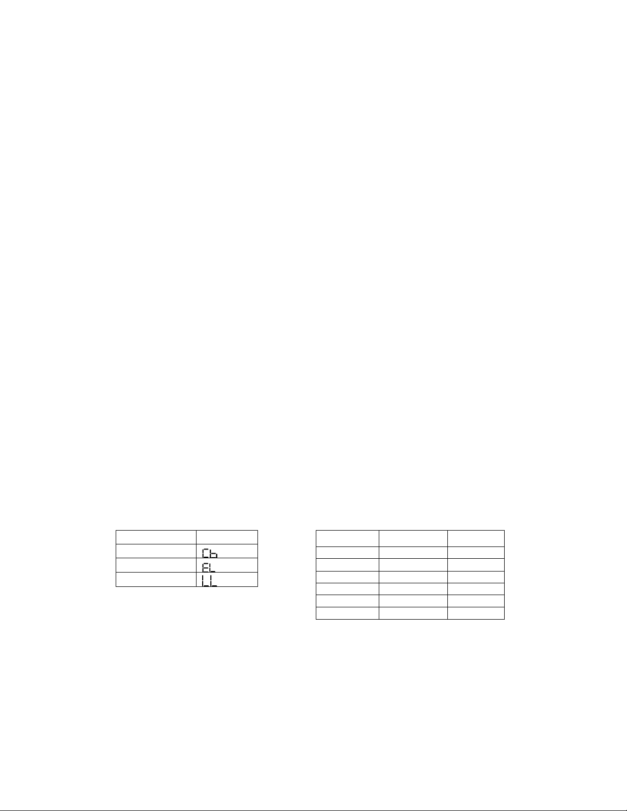
Sensor
Parameter
Cabinet Air
Evaporator Coil
Liquid Line
Table 4
8
I. d - Troubleshooting Traulsen Intela-Traul Sensors
Quick Reference Table 6
Item
Details
Cabinet Sensor
•Green
•Control parameter
•Reads return air
•Compressor cycles off of cabinet sensor value
•If cabinet sensor reads 60⁰F (15 ⁰C) or higher the unit
will not go into defrost and you can’t put into manual
defrost.
Coil Sensor
•Blue
•Control parameter
•Reads evaporator coil temperature
•Terminates defrost
•Temperature fan delay after defrost & start up
Liquid Line Sensor
•Yellow
•Control parameter
•Reads liquid line temperature
•Triggers clean filter alarm @ 140⁰F (60⁰C) (R&A Series
Only)
•Compressor safety; Cycles compressor off @ 160⁰F
(7.1⁰C)
Sensor Open
•-40⁰F (-40⁰C)
Sensor Short
•266⁰F (130⁰C)
Sensor can fail anywhere
•Between -40 & + 266 (-40⁰F & (130⁰C)
Sensor Test
•32K Ω @ 32⁰F (0⁰C)
Alarm Codes (R&A Series
Only)
•Open or shorted cabinet sensor
•Open or shorted cabinet sensor
•Open or shorted evaporator coil sensor
•Open or shorted evaporator coil sensor
•Open or shorted liquid line sensor
•Open or shorted liquid line sensor
Table 6
9
I. d - Troubleshooting Traulsen Intela-Traul Sensors
Advanced Trouble Shooting Tips
There are a variety of reasons for the symptoms listed in Table 7. This troubleshooting table is
intended to address the most common reasons associated with the Intela-Traul sensors only.
Further troubleshooting outside the scope of this document may be required.
Symptom
Possible Causes
Cabinet temperature display reads
lower temperature than actual cabinet
temperature
•Evaporator coil is frozen up
•Defective cabinet sensor
•Cabinet sensor not in proper location
Cabinet temperature display reads
higher temperature than actual
cabinet temperature
•Defective cabinet sensor
•Air flow obstruction
•Cabinet sensor not in proper location
Evaporator coil is frozen up
•Evaporator coil sensor is out of tolerance and
terminating defrost to soon
•Cabinet air sensor is out of tolerance causing
cabinet air temp to run too low
Display temperature reads -40⁰F
(-40⁰C)
•Cabinet sensor is open
•Cabinet sensor is disconnected
•Cabinet sensor wire harness is open
•Cabinet sensor pin connector is loose or has a
weak connection
Compressor cycles off before cabinet
temperature is satisfied
•Liquid line sensor is out of tolerance and
return to high of a temperature causing the
compressor to cycle off
•Liquid line is reaching 160⁰F (71.1⁰C) and
cycling the compressor off on high temp limit
Table 7
10
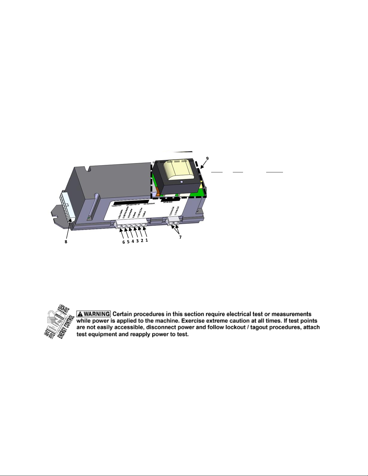
I. e - Troubleshooting Traulsen Intela-Traul MIT II Relay Module
Relay Module Function:
The Traulsen Relay Module is a long black rectangular box approximately 2 x 2 x 7 inches (5.08
X 5.08 X 17.08 centimeters) located behind the controller (front panel display) that contains
several switching relays. The relays inside the module are used to send line voltage to the
compressor (or heaters if a Hot Food box) fan motor(s), or defrost heaters or defrost solenoids,
as needed. The actuation of these relays is controlled by low voltage DC signals sent from the
Intela-Traul™ Control.
Relay Module Architecture:
Relay Module Control Voltage:
Relay control voltage is checked at the 18pin connector which delivers a range of 1-5VDC to the
relay module when the control is calling for a relay to be energized. When checking for relay
control voltage the 18pin connector MUST remain connected.
Note: Items 1, 3, & 4 are equipped with snubber circuits to reduce arcing and increase relay life. As
result Line Voltage will always be measured at the relay output regardless of relay state, open/closed.
Item # Color Function
1 Purple 115vac Output to Defrost Heater
2 Black 115vac Input Line Voltage Power
3 Gray 115vac Output to Evaporator Fan/Blower(s)
4 Orange 115vac Output to Door Frame Heater(s)
5 White 115vac Line Voltage Neutral
6 Yellow 115vac Input from Door Switch(s)
7 Pink 12VDC Output Compressor Relay Control Voltage
8 18pin connector 1-5VDC Control Voltage from Intela-Traul™ Controller
9 Transformer Line Voltage to 12V Transformer
Figure 3
11
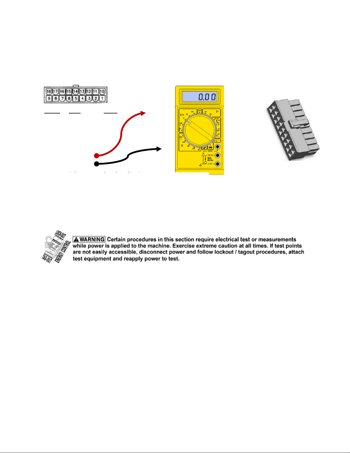
I. e - Troubleshooting Traulsen Intela-Traul MIT II Relay Module
Relay Module Control Voltage (Cont):
Relay Module Output Voltage:
If the 1-5VDC control voltage from the Intela-Traul™ has been confirmed but the corresponding
component is not energized output voltage from the relay module needs to be confirmed. The
simplest way to confirm whether or not the relay inside the relay module has failed is to jump out
the relay contacts. You can do this by unplugging the six pin connector and jump pin 2 (Black,
115vac input) to the corresponding output pin. If the component energizes then the relay
module likely needs to be replaced. If the component still does not energize then further
troubleshooting of the component is needed.
Pin No.
Color
Signal
1
Gray
Blower
2
Orange
Door Heater
3
Green
Alarm From Controller
4
Black
Return to Horn
5
Unused
6
Unused
7
White/Purple
-RS485
8
Black
Ground
9
White
12vac
10
Blue
Compressor
11
Purple
Defrost
12
Yellow
Door Open Signal
13
Red
Power to Horn
14
Unused
15
Unused
16
Pink
+RS485
17
Red
12 VDC Controller Power
18
Black
12vac
Check control voltage by inserting meter leads into the
back of the 18pin connector at the appropriate points.
18pin connector must be connected to the relay
module.
Figure 4
12
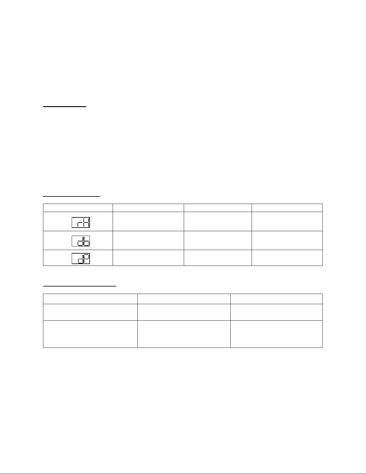
I. f - RH Sensor Module
The Intela-Traul RH module (Relative Humidity Sensor) is found on the Traulsen Energy Star
rated units, from October 2014 to the present. This technical bulletin may not cover all the
situations that may arise in the field and final diagnosis of field based equipment is the sole
responsibility of the technician contracted to perform any work required.
Functionality:
The RH module senses the ambient temperature and relative humidity and communicates the
information to the MIT II control. The MIT II control uses this data to perform the following tasks.
As seen in Table 8.
•Cycle the door heater based on ambient temperature and humidity conditions.
•Increase/decrease the intervals between defrosts based on the number of door
open/close events and the ambient temperature conditions. + or -75%.
Parameters Table:
Displayed
Parameter Name
Sample Value
Description
Relative Humidity
(Ambient)
55.0
Relative humidity of
the room.
Dry Bulb
Temperature
75.0
Ambient temperature
of the room.
Dew Point
Temperature
65.0
Calculated dew point
temperature.
Table 8
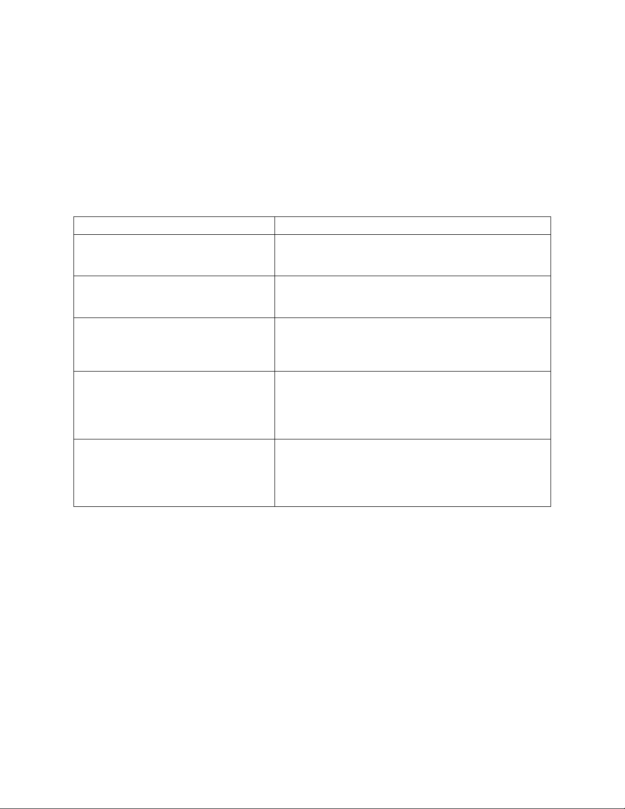
Troubleshooting Table:
Symptom
Possible cause
Solution
Excessive condensation on
the door.
Inaccurate reading from the
RH module.
Unplug RH sensor. Replace
the RH sensor module.
Coil freezes up.
The RH module extends the
interval between defrost
based on ambient conditions.
Unplug RH sensor. Put unit
into manual defrost. Replace
RH sensor.
Table 9
Note: You can disconnect the RH Sensor and the unit will run with its default settings.

13
Section II
Refrigeration System
14
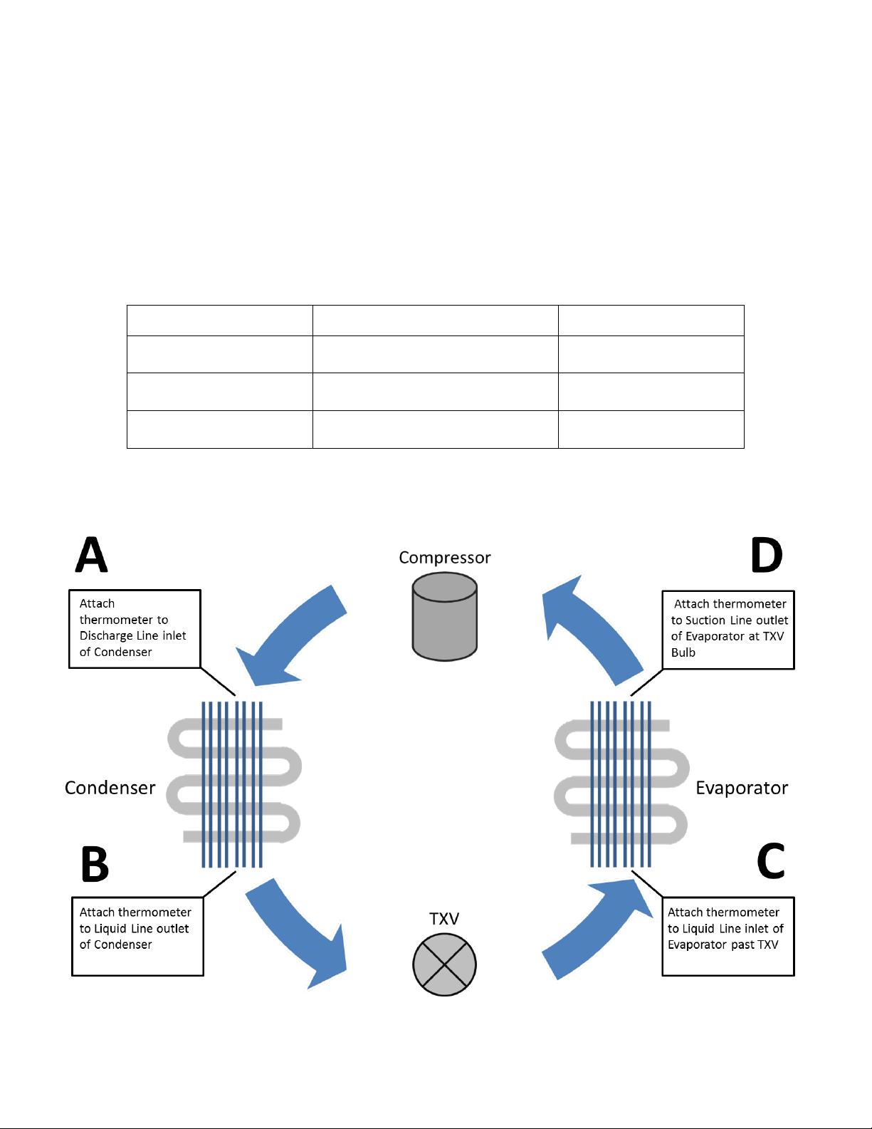
II. a - Troubleshooting Traulsen Refrigeration System
Introduction:
This is to inform the field how to trouble shoots the refrigeration system with the use of a
thermometer. As seen in Figure 5.
Trouble Shooting Refrigeration System by Temperature:
Use Table 10 and corresponding chart (Figure 5) to aid in troubleshooting a Traulsen
refrigeration system with the use of thermometers.
ITEM
FORMULA
TRAULSEN SPEC
Condenser Split
(A + B)/2-Ambient Temperature
30OF (-1.1OC)
Sub-cooling
(A + B)/2-B
4OF to12OF
(-15.5⁰C -11.1⁰C)
Evaporator Superheat
D-C
5OF to 7OF
(-15⁰C to 13.9⁰C)
Table 10
Note: Unit must be running for at least 5-10 minutes before checking temperatures and insulate sensing bulb
of thermometer for most accurate readings.
Figure 5

15
II. b - TXV Troubleshooting
Standard Operating Parameters:
•Superheat –7⁰F(-13.9⁰C)
•Subcooling –4OF-12OF (-15.5⁰C TO -11.1⁰C)
Troubleshooting:
Table 11
Moisture Contamination:
A restriction caused by moisture will thaw when the TXV is warmed and the system will begin to
function properly until the moisture finds its way back to the TXV and freezes at the orifice
again. See Table 11.
Superheat
Subcooling
Diagnosis
Above 7F
Below 4F
Refrigerant Charge is Low
Below 5F
Above 12F
System Overcharged
Above 7F
Above 12F
Restriction in High Side or Metering Device
(As measured in Figure 5, Page 14)

16
II. c - Troubleshooting a Frozen Evaporator Coil
Table 12 is intended to aid in diagnosing the root cause of a frozen evaporator coil on a
Traulsen upright reach-in refrigerator or freezer. This may not cover all situations that may arise
in the field and final diagnosis of field based equipment is the sole responsibility of the
technician contracted to perform any work required.
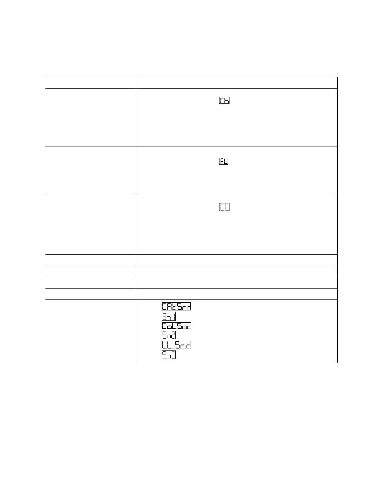
Frozen Evaporator Troubleshooting Table
Potential Causes
Details
Cabinet Sensor out of tolerance
(See TTB006 Sensors for sensor
troubleshooting)
•Color: Green
•Control parameter
•Reads return air
•Compressor cycles off of cabinet sensor value
Coil Sensor out of tolerance
(See TTB006 Sensors for sensor
troubleshooting)
•Color: Blue
•Control parameter
•Reads evaporator coil temperature
•Terminates defrost @ 45⁰F (7.2⁰C)
•Fan delay
Ambient Air Infiltration
•Door(s) not closing properly
•Gasket(s) not sealing properly
•Door(s) left open for extended periods of time
•Evaporator hump cover not sealed properly
Compressor relay stuck closed
•Coil voltage 12VDC
•Coil wires: Pink
•Contacts
oCommon: Black wire
oN/O: Blue wire
Lack of Air Flow
•Evaporator fan motor not functioning
•Obstruction in air duct or at evaporator coil
Refrigeration System (Traulsen
recommends the refrigeration system be
tested using the methods outlined in
TTB009)
•Low charge
•Restricted metering device
•Moisture/contaminates in the system
Defrost Heater
•Defrost heater open
•Defrost heater circuit or relay open
Control Settings
•Set point to low (refrigerator only)
oControl parameters: or &
(depending on the age of control system)
•Defrost lockouts set to frequently
oControl parameters: , , ,
Table 12
17
II. d - Compressor Troubleshooting
Tools Required:
•Basic hand tools
•Clamp around amp meter
•Volt Ohm meter
•Basic 3 in 1(1/2 HP)
Terminology:
•OEM –Original Equipment Manufacturer –Refers to the manufacturer of a piece of
equipment or component.
•RLA –Rated Load Amps –The OEM test conditions amperage rating (does not
necessarily indicate the normal running amperageas conditions and applications can vary
from OEM test conditions)
•LRA –Locked Rotor Amps –The OEM test condition lock rotor amperagerating indicating
the expected amperage at which a motor does not turn when power is applied.
•Start Components –The capacitor and relay combinations used to start and/or run a
compressor motor consist of a start capacitor and start relay if IAA is shown on the serial
number of the compressor. If CAA is listed then there will be a potential relay along with a
start capacitor and a run capacitor.
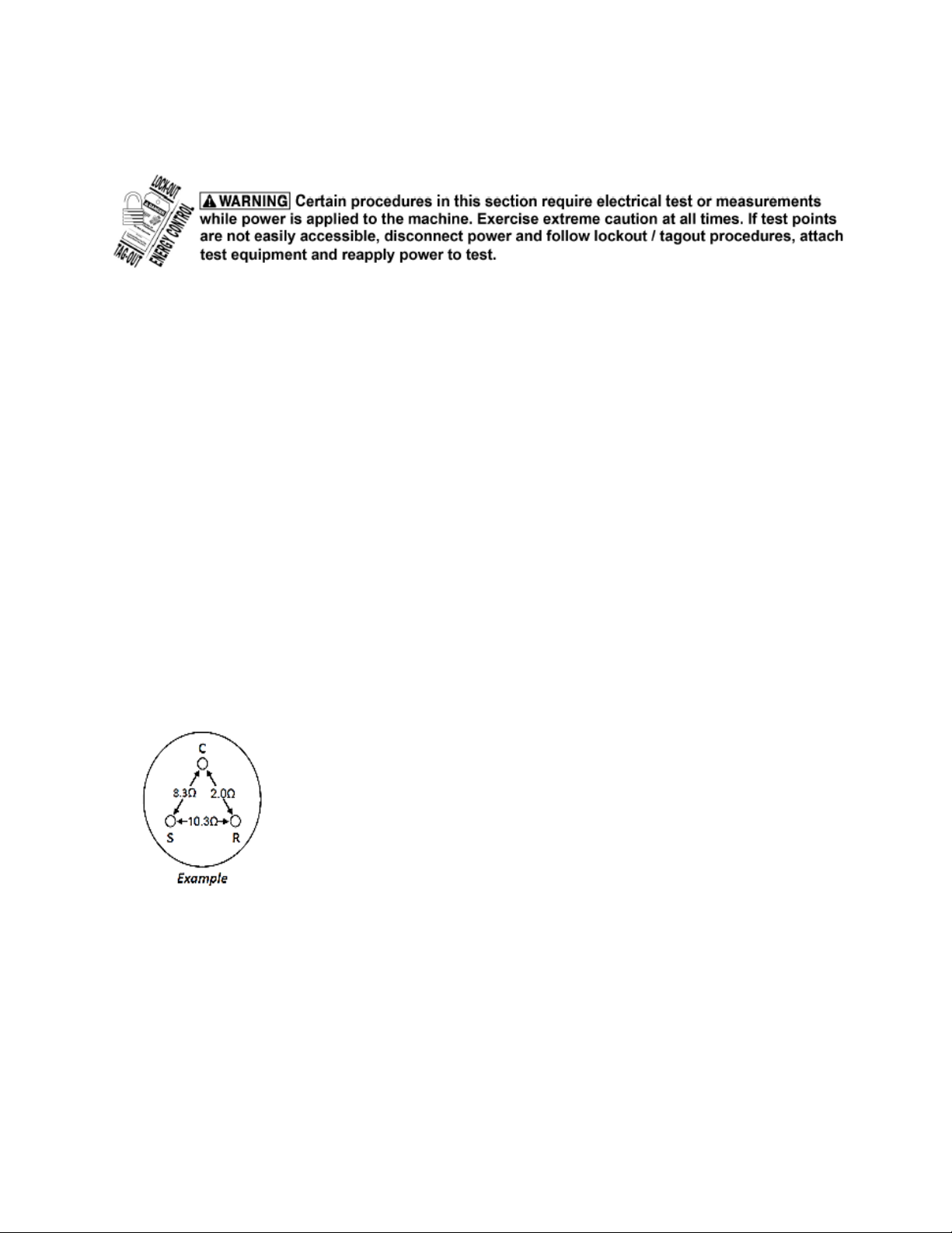
Ω= OHM= Unit Resistance
R= Run
S= Start
C= Common
Figure 6 shows the readings of the resistance through the compressor
motor windings. (C-S C-R). If the windings are good the start winding
resistance (C-S) will always be higher than the run winding resistance
(C-R).
Note: This example shows one set of possible combinations that can be seen in the field. Resistance values
will vary between different compressors.
Figure 6

18
II. d - Compressor Troubleshooting
Basic Troubleshooting:
•What is my amp draw and voltage when the compressor is starting?
•What is the resistance of the windings?
•What is the RLA (Rated Load Amps) of the compressor?
•What is the LRA (Locked Rotor Amps) of the compressor?
•Check the start components?
Symptom Reason Possible Resolution
0 amps
Check for voltage between C &
R terminals.
No: Check external overload & find
where power loss is.
Yes: open winding or the internal
overload is open
Amps lower then
RLA
Lower head & high suction.
Weak valves, busted crankshaft or
connecting rod.
Slightly higher
amps then RLA
Overload opens after
compressor runs for a time.
Bad run capacitor, tight bearings, or
winding issues.
Very high amps
but not LRA
Issue with compressor
windings.
Ohm windings and compare with
manufacturer’s resistances.
Reading LRA
Compressor not starting,
reading 5 to 6 times RLA.
Check start capacitor, start relay
&wires for burning, try 3 in 1.
Check voltage drop (+/-10%) and for
resistance.
Table 13

19
Section III
Compact & Milk Cooler Controls
Other manuals for G-Series
3
Table of contents
Other Traulsen Commercial Food Equipment manuals


Popular Commercial Food Equipment manuals by other brands


Diamond
Diamond AL1TB/H2-R2 Installation, Operating and Maintenance Instruction

Salva
Salva IVERPAN FC-18 User instructions

Allure
Allure Melanger JR6t Operator's manual

saro
saro FKT 935 operating instructions

Hussmann
Hussmann Rear Roll-in Dairy Installation & operation manual

Cornelius
Cornelius IDC PRO 255 Service manual

Moduline
Moduline HSH E Series Service manual

MINERVA OMEGA
MINERVA OMEGA DERBY 270 operating instructions

Diamond
Diamond OPTIMA 700 Installation, use and maintenance instructions

Diamond
Diamond G9/PLCA4 operating instructions

Cuppone
Cuppone BERNINI BRN 280 Installation

Arneg
Arneg Atlanta Direction for Installation and Use