Traulsen TB Series User manual
TB SERIES GLYCOL PIZZA/SALAD/SANDWICH PREP TABLES
Hours of Operation: Monday - Friday 7:30 a.m. - 4:30 p.m.
(CST)
4401 Blue Mound Road Fort Worth, Texas 76106 (USA)
OWNER’S MANUAL
*Please Note: This manual is intended for use with the above referenced equipment manufactured after April 01, 2019. To obtain a copy of the correct Owner’s Manual to support
the same products manufactured prior to this date, please contact Traulsen Service at (800) 825-8220.
-1-
I. THE SERIAL TAG Page 1
a) Serial Tag & Location Page 1
b) Reading The Serial Tag Page 1
II. RECEIPT INSPECTION Page 2
III. INSTALLATION Page 2
IV. PRESTART CHECKS Page 3
V. OPERATION Page 3
a) Operation Page 3
b) Pan Chiller Page 3
c) Lower Storage Cabinet Page 4
d) Shutdown For Extended Period Page 4
e) Removing Food Product At Night Page 4
f) Leaving Food Product In The Unit
Throughout The Night Page 4
VI. CONTROL BASICS Page 4
a) Control Display Page 4
VI. CONTROL BASICS (continued)
b) Unlocking the Keypad Page 5
c) Adjusting The Cabinet Temperature
Setpoint Page 5
d) Adjusting The Rail Temperature
Setpoint Page 5
e) Initiating A Defrost
VII. General Care Page 5
a) General Care Page 5
b) Adjusting The Shelves Page 5
c) Cleaning The Condenser Page 6
d) Cleaning The Lower Storage Cabinet Page 6
VIII. TROUBLE SHOOTING Page 6
IX. SERVICE/WARRANTY INFORMATION Page 7
a) Service Information
b) Service Support Information
c) Warranty Registration
I. THE SERIAL TAG
I. a - SERIAL TAG & LOCATION
The serial tag is a permanently afxed label on which is recorded
vital electrical and refrigeration data about your Traulsen product,
as well as the model and serial number. This tag is located in the
right interior compartment on all standard KBP Series models.
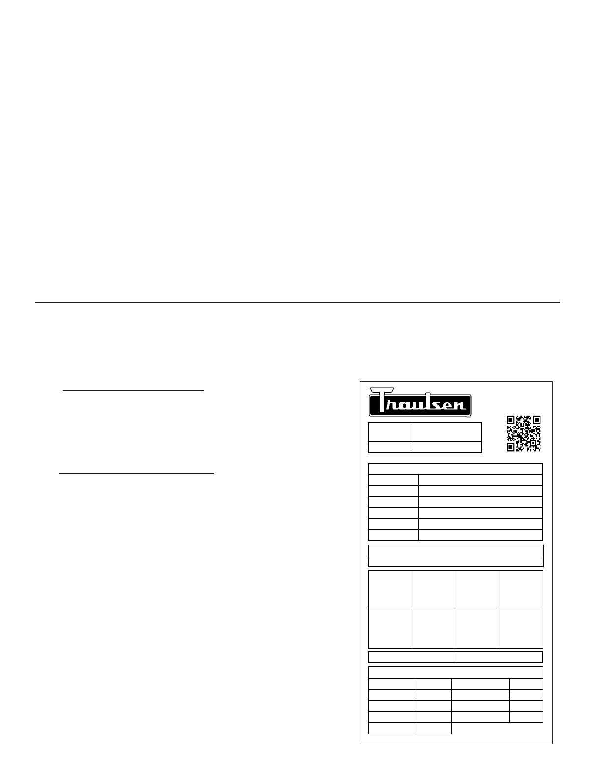
I. b - READING THE SERIAL TAG
• Model = The model # of your Traulsen unit
• (S/N) Serial Number = The permanent ID# of your Traulsen
unit
• Refrigerant SYS1= System 1 Refrigerant type used and refrigerant
charge
• Design Pressure= System 1 High and Low Pressure
• Refrigerant SYS2= System 2 Refrigerant type used and refrigerant
charge
• Design Pressure= System 2 High and Low Pressure
• Volts = Voltage
• Hz = Cycle
• Total Current = Maximum amp draw
• Min Circuit Amps = Minimum circuit ampacity
• Agency Labels = Designates agency listings
This unit is listed to UL 471, CSA 120 and NSF 7 by an approved NRTL.
Consult the factory or unit data plate for approval information.
• Components = Component Ratings
4401 Blue Mound Rd.
Ft. Worth, TX 76106
800-825-8220
Input Power (ELIN) -FOR INDOOR USE ONLY
115-208/230V ~ 60Hz 8.0A (8,0A)
MODEL:
MODELO:
MODELE: RDT232WUT-FHS
S/N: T25364A14
REFRIGERANT / REFRIGERANTE / RÉFRIGÉRANT
SYS1 (REFM): R-134a 8.4oz 238.1 g (238,1 g)
Hi Press. (PRESH): 500psi 3.45 MPa (3,45 Mpa)
Lo Press. (PRESL): 250 psi 1.72 Mpa (1,72 Mpa)
SYS2 (REFA): R-404a 12.5oz 354.4g (354,4g)
Hi Press. (PRESH): 500psi 3.45MPa (3,45MPa)
Lo Press. (PRESL): 250psi 1.72Mpa (1,72Mpa)
(Symbol 1)
(Alt Safety / Other
1)
(Symbol 2)
(Alt. San / Other 2)
(Symbol 3)
(Alt. En. / Other 3)
(Symbol 4)
(WEEE)
(Symbol 5)
(Safety)
(Symbol 6)
(Sanitaon)
(Symbol 7)
(Energy)
(Symbol 8)
(Customer QR
Code / Other 4)
Device/Part Number: PartNum (UL/NSF Notes)
SCAN FOR SERVICE INFO
COMPONENTS / COMPOSANTS / COMPONENTES
COMP AMPS: EVAP FAN AMPS:
COND FAN AMPS: LIGHT WATTS:
DEF HTR AMPS: CTRL AMPS:
DOOR HTR AMPS: MIN AMPS:
MAX AMPS:
370-60297-00 REV.A 11/20/14

-2-
II. RECEIPT INSPECTION III. INSTALLATION
II. a - RECEIPT INSPECTION
Carefully inspect your Traulsen unit for damage during
delivery. If damage is detected, you should save all crating
materials and make note on the carrier’s Bill of Lading
describing the damage. A freight claim should be led
immediately. If damage is subsequently noted during or
immediately after installation, contact the respective carrier
and le a freight claim. There is a ve (5) day limit to le
freight damage with the carrier. Under no condition may a
damaged unit be returned to Traulsen without rst obtaining
written permission (return authorization). You may contact
Traulsen customer care at 800-825-8220.
Some models may use R-290 (Propane)
as a refrigerant. If ammable refrigerant is present, follow
instructions as labeled on the unit. Proper care must be taken
to avoid any damage to the refrigeration system including
refrigerant tubing, condenser, evaporator coils during
handling, moving, installation and cleaning as it may cause
risk of re or explosion. If damaged, unit must be moved to
well ventilated area away from any sources of ignition.
Further service and repair must be performed by qualied
refrigeration technicians familiar with applicable safety
standards for ammable refrigerants. Technicians must
use appropriate personal protective equipment and follow
applicable safety precautions to avoid risk of re or explosion.
Do not damage evaporating catch pan support
brackets on the bottom of the unit when lifting the prep table
from the shipping pallet (see photo below)!
III. a - INSTALLATION
Prep table models can be installed with no clearance at the
back and sides of the units.
All units are supplied with a cord and plug, which can simply
be plugged into a dedicated appropriately sized outlet.
Some components are packed and shipped inside the lower
storage cabinet to avoid damage during shipment. Remove
these items from the cabinet and remove packing materials.
If unit is equipped with shelves, cut and remove the plastic
ties holding the shelves in place.
Place cutting board on rail so that holes in cutting board line
up with pins on the counter top.
Slide evaporating catch pan over support brackets all the
way to the back of the prep table positioning it below the
prep table drain outlets.

-3-
III. a - INSTALLATION (continued)
Open the condensing compartment hinged louver door and
check the glycol level in plastic expansion tank.
A non-toxic food grade 35% Propylene Glycol level in the
overow tank may be above the “Maximum Fill Line” or not
visible in the bottle when the unit arrives. Propylene Glycol
level in the overow tank varies and may or may not be
visible in the bottle based on the following conditions:
• Variations in the environment temperature;
• Variation in unit temperature.
If the unit is powered down after normal working hours, the
Propylene Glycol level may rise above the “Maximum Fill
Line”. This is normal operation and is inuenced by the above
conditions.
Close louver door remove rear condensing unit cover and
check if glycol ball valve is in the open position. Re-attach
rear louver.
Cut zip-tie securing electrical cord and plug cord into wall
socket.
GAS REFRIGERATION LINES IN CONDENSING
UNIT AREA ARE SHIPPED UNDER PRESSURE!
IV. PRESTART CHECKS
IV. a - PRESTART CHECKS
Glycol Prep Tables are shipped with factory pre-set
temperature settings. Although Traulsen Glycol Prep Tables
are tested at factory before shipment, there are variables
that can affect cooling performance of the unit:
• Ambient Temperature
IV. a - PRESTART CHECKS (continued)
• Humidity Level
• Air stream patterns
• Over-shelves/Heat lamps
• Product temp prior to loading into refrigerated pan
chiller well.
• Surrounding equipment.
All temperature settings can be adjusted by the Customer
or Authorized Traulsen Service Agent within +/- 3 °F.
V. OPERATION
V. a - OPERATION
Some models may use R-290 (Propane)
as a refrigerant. Consult detailed owner’s manual available
at www.traulsen.com before attempting to install or service
units with R-290 or other ammable refrigerants. All safety
precautions must be followed to avoid risk of re or explosion.
Contact Traulsen for additional information at 800-825-8220.
Plug cordset into wall outlet (self contained models). Open
the louver door, ip the main power switch ON and close the
door. Observe the Temperature Display through the opening
in the louver door.
When the Glycol Temperature cools to 30°F (-1°C), the unit
is ready to go!
V. b - PAN CHILLER
To ensure proper food temperatures are maintained
in exposed insert pans, the following conditions are
recommended.
1. All food brought to line must be at 41°F (5°C) or below.
2. No direct air blowing on food product from other
equipment in the kitchen (max air velocity 50 FPM/0.234
Meter/second).
3. Room ambient temperatures of 86°F (30°C) or less
around working area of Pan Chiller.
4. All shelving mounted over insert pans (with heated
equipment above it) must be insulated. No line of sight
from radiant heat sources to insert pans.
5. Occasional stirring of certain foods may be required in
order to maintain consistent temperatures.
III. INSTALLATION (continued) IV. PRESTART CHECKS (continued)

-4-
V. b - PAN CHILLER (continued)
6. Some food products chill faster than others i.e., lettuce,
dried tomatoes, etc.
7. For remote refrigerators with pan chiller systems, it is
imperative that the existing refrigeration equipment be
sized properly and in good working condition.
8. Traulsen recommends specified pans for optimum
performance (see spec sheet for recommended
suppliers).
V. c - LOWER STORAGE CABINET
The lower storage cabinet is designed to maintain
temperature between 33°F (0.55°C) and 40°F (4°C). If
the base is overloaded with warm food products, a certain
amount of time is required to remove heat from items before
operating temperatures can be maintained. The system is
only designed for storage of refrigerated product. Frequently
opening the doors or drawers will increase the temperature
in the cabinet and will require a certain amount of time to
recover.
V. d - SHUTDOWN FOR EXTENDED PERIOD
If the prep table and lower storage cabinet are not to be
used for an extended period of time, disconnect the electrical
power supply and open the doors (or drawers) to the lower
storage cabinet. As soon as the divided bars and the cabinet
have warmed to room temperature, wipe out the pan chiller
cavity and base interior.
V. e - REMOVING FOOD PRODUCT AT NIGHT
If you are storing product in the refrigerated storage base
and food needs to be removed from Pan Chiller at night,
simply close the night cover after removing food pans. This
will improve energy efciency during overnight hours. If ALL
food is removed from unit (pan chiller and refrigerated base
both empty), ip the ON/OFF switch to shut down entire unit.
To turn unit back on, ip switch ON.
V. f - LEAVING FOOD PRODUCT IN THE UNIT
THROUGHOUT THE NIGHT: (Recommended)
This unit is preset at factory and does not require periodic
shutdowns for the defrost cycle. This upgraded glycol
refrigeration system eliminates the operational burden
of removing food pans prior to the defrost period or for
overnight storage. No defrost cycle means that food can be
consistently cooled 100% of the time, day or night.
V. f - LEAVING FOOD PRODUCT IN THE UNIT
THROUGHOUT THE NIGHT (continued)
Plastic wrap should be placed over exposed food prior to
closing the night cover to help prevent condensation from
getting into the food.
The night cover must be closed if food is being left in the
pan chillers overnight.
VI.CONTROL BASICS
VI. a -CONTROL DISPLAY
Your equipment has been configured for optimum
performance. This document will serve as guide, if there is a
need to adjust the controller settings via the simple display.
On the left side is a unlock symbol and a three digit LED
display. This typically displays the cabinet temperature and
the rail temperature, prexed with ‘C’ and ‘r’ respectively.
The cabinet and rail temperature are displayed alternately.
At the center of the display there are four icons that reect
the status of the compressor, fans, defrost and alarms. On
the right are ve capacitive touch buttons. They will be used
to access the controller settings.
Status and Button Symbols:
Compressor Status
Fan Status
Defrost Status
Alarm / Door Open
Unlock Symbol
+ or Next Key
- or Previous Key
Unlock or Modify Key
Esc or Back Key
Display or Enter Key
V. OPERATION (continued) V. OPERATION (continued)
Table of contents
Other Traulsen Commercial Food Equipment manuals


Popular Commercial Food Equipment manuals by other brands


Diamond
Diamond AL1TB/H2-R2 Installation, Operating and Maintenance Instruction

Salva
Salva IVERPAN FC-18 User instructions

Allure
Allure Melanger JR6t Operator's manual

saro
saro FKT 935 operating instructions

Hussmann
Hussmann Rear Roll-in Dairy Installation & operation manual

Cornelius
Cornelius IDC PRO 255 Service manual

Moduline
Moduline HSH E Series Service manual

MINERVA OMEGA
MINERVA OMEGA DERBY 270 operating instructions

Diamond
Diamond OPTIMA 700 Installation, use and maintenance instructions

Diamond
Diamond G9/PLCA4 operating instructions

Cuppone
Cuppone BERNINI BRN 280 Installation

Arneg
Arneg Atlanta Direction for Installation and Use