Traulsen TRP Series User manual

OWNER’S MANUAL
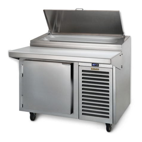
TRP-SERIES PREP TABLES
Hours Of Operation: Monday - Friday 7:30 a.m. - 4:30 p.m.
(CST)
Quality Refrigeration
4401 Blue Mound Road Fort Worth, Texas 76106 (USA)

TRP-SERIES PREP TABLE
TABLE OF CONTENTS
1 THE SERIAL TAG
A THE SERIAL TAG & LOCATION PAGE 3
B READING THE SERIAL TAG PAGE 3
2 RECEIPT INSPECTION PAGE 3
3 INSTALLATION
A UNPACKING PAGE 3
B LOCATING THE EQUIPMENT PAGE 3
C INSTALLING PARTS SHIPPED LOOSE-CUTTING BOARD PAGE 4
D INSTALLING PARTS SHIPPED LOOSE-COMPRESSOR FILTER PAGE 4
E INSTALLING PARTS SHIPPED LOOSE-ELECTRIC CONDENSATE EVAPORATOR PAGE 5
4 REFRIGERATION LINES PAGE 5
5 ELECTRICAL CONNECTIONS PAGE 5
6 PRESTART CHECKS
A DEFROST TIME CLOCK SETTINGS (PAN CHILLERS) PAGE 6
B REMOVING FOOD PRODUCT AT NIGHT PAGE 6
C LEAVING FOOD PRODUCT IN OVERNIGHT PAGE 6
D TEMPERATURE CONTROL SETTINGS PAGE 7
7 OPERATION
A PAN CHILLER PAGE 8
B LOWER STORAGE CABINET PAGE 8
C SHUTDOWN FOR EXTENDED PERIODS PAGE 8
8 MAINTENANCE PROCEDURES
A CLEANING PAGE 9
B LOWER STORAGE CABINET PAGE 9
C CLEANING: PAN CHILLER PAGE 10
D CONDENSING UNIT PAGE 10
E EVAPORATOR COILS PAGE 11
9 TROUBLE SHOOTING PAGE 11
10 TIPS PAGE 12
11 SERVICE PAGE 12
12 WIRING DIAGRAM PAGE 13
13 WARRANTIES PAGE 14
This Traulsen unit is built to our highest quality standards. We build our refrigerators this way as a matter of pride.
This philosophy has made Traulsen the leader in commercial refrigeration since 1938. We thank you for your choice
and condence in Traulsen equipment and we know you will receive many years of utility from this equipment.
TRP SERIES
Page 2

1. THE SERIAL TAG
1A – SERIAL TAG & LOCATION:
The serial tag is a permanently afxed label on which is recorded vital electrical and refrigeration data about your Traulsen
product, as well as the model and serial number. This tag is located inside the lower storage cabinet on the right hand wall
on all standard TRP models. Prior to installation, test the electrical service to assure that it agrees with the specications of
the equipment marked on the serial tag. An example of the serial tag is shown below (See Fig. 1).
1B - READING THE SERIAL TAG:
FIELD DESCRIPTION
Model The model # of your Traulsen unit
(S/N) Serial Number The permanent ID# of your Traulsen unit
Refrigerant SYS1 System 1 Refrigerant type used and
refrigerant charge
Design Pressure System 1 High and Low Pressure
Refrigerant SYS2 System 2 Refrigerant type used and
refrigerant charge
Design Pressure System 2 High and Low Pressure
Volts Voltage
Hz Cycle
Total Current Maximum amp draw
Min Circuit Amps Minimum circuit ampacity
Agency Labels Designates agency listings
This unit is listed to UL 471, CSA 120
and NSF 7 by an approved NRTL. Con-
sult the factory or unit data plate for
approval information.
Components Component Ratings
Fig. 1
2. RECEIPT & INSPECTION
All Traulsen products are factory tested for performance and
are free from defects when shipped. The utmost care has
been taken in crating this product to protect against damage
in transit.
Carefully inspect your Traulsen unit for damage during deliv-
ery. If damage is detected, you should save all crating mate-
rials and make note on the carrier’s Bill of Lading describing
the damage. A freight claim should be led immediately. If
damage is subsequently noted during or immediately after
installation, contact the respective carrier and le a freight
claim. There is a ve (5) day limit to le freight damage with
the carrier. Under no condition may a damaged unit be re-
turned to Traulsen without rst obtaining written permission
(return authorization). You may contact Traulsen customer
care at (800) 333-7447 to request a return.
3. INSTALLATION
3A - UNPACKING:
Inspect equipment for shipping damage prior to installation.
If shipping damage is found, save the packing materials and
contact the carrier within ve (5) days of delivery.
Some components are packed and shipped inside the lower
storage cabinet to avoid damage during shipment. Remove
these items from the cabinet and remove packing materials.
See “Installing Parts Shipped Loose” for installation instruc-
tions. If unit is equipped with shelves, cut and remove the
plastic ties holding the shelves in place.
3B - LOCATING THE EQUIPMENT:
Prep table models of lengths above 36” (914.4mm) can be
installed with no clearance at the back and sides of the units.
Units 36” (914.4 mm) or shorter have a rear mount compres-
sor and require a minimum clearance of 3” (76.2mm) at the
back and sides of the unit. This allows for sufcient air cir-
culation of the condensing unit. Failure to provide adequate
ventilation may cause severe compressor damage, and will
void warranty.
TRP SERIES
Page 3

TRP SERIES
Page 4
3. INSTALLATION (continued)
3C - INSTALLING PARTS SHIPPED LOOSE: CUTTING BOARD
Place cutting board so that the holes in the cutting board line up with the pins on the counter top (See Fig. 2).
Fig. 2
3D - INSTALLING PARTS SHIPPED LOOSE: COMPRESSOR FILTER
Remove louvered panel by lifting up and pulling out entire panel. Slide the lter into the tracks located below the compressor
compartment. Be careful not to catch the lter on sharp edges when installing. Replace louvered panel by installing top of
panel into track and pushing in the bottom so that the locking clips t inside the opening (See Fig. 3).
Fig. 3

TRP SERIES
Page 5
3. INSTALLATION (continued)
3E - INSTALLING PARTS SHIPPED LOOSE: CONDENSATE CATCH PAN
Some units may come with the condensate catch pan shipped loose. Place the catch pan over the pan support brackets.
Slide the catch pan all the way to the back of the table under the drain outlets. NOTE: Drain should be located above the
condensate evaporator opening (See Fig. 4).
Fig. 4
4. REFRIGERATION LINES (REMOTE UNITS)
REFRIGERATION LINES ARE SHIPPED
UNDER PRESSURE. USE CAUTION WHEN OPENING
LINES.
On remote units, refrigeration lines for suction and supply
are located on the back of the unit near the bottom (See Fig.
4). The suction line is marked "Suction" and is 3/8" copper
tubing. The supply line is 1/4" copper. See "Electrical Con-
nections" section for wiring instructions.
If no holding charge is evident upon opening lines, contact
Traulsen Service and Parts Department at (800) 825-8220
immediately.
Cut refrigeration tubing with tube cutter (not a hacksaw) and
deburr end of tube. Degrease tubing prior to eld connec-
tion. Use Sil-Fos® 5% for refrigerant line brazing. 50/50 or
cold solder is not acceptable for use.
For system charge, follow remote refrigeration system man-
ufacturer's instructions.
5. ELECTRICAL CONNECTIONS
Refer to the wiring diagram shipped with the unit located in-
side the compressor compartment or on the back of the unit.
CORD CONNECTED UNITS (Self-Contained models)
Plug the unit into a properly sized outlet. See data plate lo-
cated inside storage cabinet for circuit sizing.
WARNING: THIS MACHINE IS PROVIDED WITH A
THREE-PRONGED GROUNDING PLUG. THE OUTLET
TO WHICH THIS PLUG IS CONNECTED MUST BE PROP-
ERLY GROUNDED. IF THE RECEPTACLE IS NOT THE
PROPER GROUNDING TYPE, CONTACT AN ELECTRI-
CIAN.
PERMANENTLY WIRED UNITS (Remote models)
A junction box located on back of the machine near bottom is
provided for electrical eld connections. See wiring diagram
shipped with unit on the back of the unit for electrical ratings.
Table of contents
Other Traulsen Commercial Food Equipment manuals
Popular Commercial Food Equipment manuals by other brands

Diamond
Diamond AL1TB/H2-R2 Installation, Operating and Maintenance Instruction

Salva
Salva IVERPAN FC-18 User instructions

Allure
Allure Melanger JR6t Operator's manual

saro
saro FKT 935 operating instructions

Hussmann
Hussmann Rear Roll-in Dairy Installation & operation manual

Cornelius
Cornelius IDC PRO 255 Service manual

Moduline
Moduline HSH E Series Service manual

MINERVA OMEGA
MINERVA OMEGA DERBY 270 operating instructions

Diamond
Diamond OPTIMA 700 Installation, use and maintenance instructions

Diamond
Diamond G9/PLCA4 operating instructions

Cuppone
Cuppone BERNINI BRN 280 Installation

Arneg
Arneg Atlanta Direction for Installation and Use


