Astral Pool HALO DOSER User manual

H0740100_REVA
INSTALLATION MANUAL
FOR YOUR SAFETY - This product must be installed in accordance with AS/NZ 3000 - 2018 and any other local
applicable regulations. Before installing this product, read and follow all warning notices and instructions that
accompany this product. Failure to follow warning notices and instructions may result in property damage,
personal injury, or death. Improper installation and/or operation may void the warranty.
Improper installation and/or operation can create unwanted electrical hazard which can cause serious injury,
property damage, or death.
WARNING
halo®doserTM
pH Dosing Module

2
HALO®DOSER™Installation Manual
EQUIPMENT INFORMATION RECORD
DATE OF INSTALLATION
INSTALLER INFORMATION
SERIAL NUMBER
For full warranty terms and conditions and to register your
warranty, visit www.astralpool.com.au/warranty or
www.astralpool.com.nz/warranty and complete your details.
Or scan the QR code to go directly to the registration page.
Record your equipment details here for quick reference:
Model No. : ____________________________________
Serial No. : ____________________________________
For AU
For NZ

3
HALO®DOSER™Installation Manual
Table of Contents
Section 1. Important Safety Instructions .............. 4
Section 2. System Overview ...................................... 5
Section 3. Installation .................................................. 6
3.1 Plumbing and Mounting......................................................... 6
3.2 Installing the Vent Kit................................................................ 7
3.3 Enabling Dosing on the HaloChlorinator......................... 8
Section 4. Control Using the HaloChlorinator.... 9
4.1 Automatic Operation................................................................ 9
4.2 Manual Operation...................................................................... 9
4.3 Operation Via the Halo ChlorGo App.................................. 9
Section 5. Regular Maintenance .............................. 10
Section 6. Troubleshooting........................................ 10

4
HALO®DOSER™Installation Manual
Section 1. Important Safety Instructions
READ AND FOLLOW ALL INSTRUCTIONS
When installing and using this electrical equipment, basic safety precautions should always be followed, including
the following:
SAVE THESE INSTRUCTIONS
WARNING
The Halo Doser has an IP23 rating, meaning it is suitable for installation outdoors. For safe operation the Halo Doser must be
installed in the correct orientation, with the cable leaving from the bottom of the device. AstralPool strongly recommends
that installation be performed by a registered pool builder, electrician or other suitably qualified person.
CAUTION
When mixing acid or other chemicals with water, ALWAYS ADD THE ACID OR CHEMICALS TO WATER. NEVER ADD WATER TO
THE ACID OR CHEMICALS.
Some helpful considerations may include:
• Choosing plants that can withstand splash out of pool water containing chlorine and/or salt and other water purification
chemicals.
• All metal components used in and around a pool should be of a high grade, quality stainless steel.
• Careful selection of masonry products. The porosity and hardness of natural stones varies greatly. Therefore we
recommend you consult with your builder or stone contractor on the best choice for stone materials around your pool or
spa.
• Sealing all masonry products. Professionals in the stone industry specify that even natural stone, especially when
used outdoors, be sealed to prevent weathering, staining, and premature degradation. Consult with your stone or deck
contractor for the proper sealer for the masonry products you have selected to use around your pool or spa.
• For the optimal results, sealers should be reapplied on a regular basis. Reapply the protective sealer on a schedule per the
manufacturer’s instructions.
• Use of chemicals other than those recommended may be hazardous. Follow the chemical manufacturers instructions.

5
HALO®DOSER™Installation Manual
Section 2. System Overview
The Halo Doser is designed to work in conjunction with a Halo Chlorinator and can be controlled through the Halo
Chlorinators main touchscreen or through the Halo ChlorGo App.
Only one Halo Doser can be connected to a Halo Chlorinator.
The Halo Doser is not designed to work in a “stand alone”mode and cannot be controlled unless it is connected to
a Halo Chlorinator.
For further information, refer to the Halo Chlorinator Instruction Manual.
Kit Contents
Before starting, check that you have the correct parts as shown in Figure 1. If any parts are missing or incorrect,
please call your local distributor or technical support at 1300 186 875 for assistance.
1
2
3
4
5
6
7
8
9
10
HALO DOSER
INJECTION
POINT W/
50MM UNION
VENT KIT
Figure 1. Halo Doser and doser mounting kit
ITEM NO. DESCRIPTION QUANTITY
1 Halo Doser Back Plate 1
2 Halo Doser Main Body 1
3 Halo Doser Pump Body and Head 1
4 Halo Doser Pump Head 1
5 Halo Doser Tinted Visor and Label 1
6Injection T Piece 1
7 Gland Ring 1
8Gland Washer 1
9 Gland Nut 1
10 Vent Kit 1
The vent kit is supplied with 4 meters of clear tube which needs to be cut to the required length to suit the
installation. It also has a short piece of white rigid tubing used to go into the acid drum.
Two lids are supplied with the kit to suit either a
15 ltr or a 5 ltr container. (See also “Installing the Vent Kit” section.)

6
HALO®DOSER™installation manual
3.1 Plumbing and Mounting
The cable connecting the Halo Doser to the Halo
Chlorinator is 1 m long, so the doser needs to be
located within 1 m of the chlorinator. See Figure 2.
The acid injection point (where the acid goes into the
pool water) must be mounted into the pipework, after
the chlorine cell and all other equipment. Ideally the
chamber should be mounted as far away as possible,
downstream from the chlorinator cell.
If probes are being fitted, then ideally the probe
mounting should be mounted as far away as possible,
upstream from the chlorinator cell.
ACID
INJECTION
POINT
Figure 3. Chlorinator Cell and Doser Installation
The Halo Doser should be located within 2 meters of
the acid injection point.
There are 6 separate mounting holes in the back plate
which gives a number of different options for screw
positions. Once a suitable position has been found,
mount the back plate to the wall using the two (2)
mounting screws (and masonry plugs if required).
Unclip the tinted visor from the doser assembly by
gently pulling it outwards at its base. Pull enough of
the dosing pump cable out of the pump enclosure to
reach the Halo Chlorinator and then push the pump
enclosure onto the wall mounting bracket (the cable
exits the doser assembly at the bottom – take care
not to pinch it!). Secure the doser assembly to the
mounting bracket using the
two (2)
mounting screws.
See Figure 4.
Mounting Bracket
Assembly
Pump Enclosure
Assembly
Pump Assembly
Protective
Cover
1
2
3
4
*Clear
Tubing
*Clear
Tubing
*Note: Flexible clear tubing is used
for acid distribution to the pool.
The rigid white tubing is used for acid
collection from inside of the chemical drum.
Figure 4. Halo Doser Installation
Section 3. Installation
FILTER
PUMP
POOL/SPA
3 WAY VALVE
SPA RETURN
POOL RETURN
CHECK
VALVE
CELL
HALO CHLOR
HA L O
®
CH L O R
TO ACID DRUM
HEATER
HALO DOSER
INJECTION POINT
Figure 2. Typical Installation Diagram

7
HALO®DOSER™Installation Manual
3.2 Installing the Vent Kit
Tubes to be
cut to suit
installation
Tube supplied
in kit
Longer spigot
to Doser
Shorter
spigot to
wall vent
VENT
DOSER
Wall
VENT
DOSER
Acid
bottle
Keep 5 - 10 mm clearance
from bottom of container
Non-return
valve
Figure 5. Vent Kit Installation Diagram
As supplied, the white tube is designed to suit a 5 ltr
and 15ltr containers. The tube may need to be cut to
suit other drum sizes being used. Firstly insert the non
return valve into the rigid white tube, with the arrow
point up. (when fitted correctly you should be able to
blow through the valve into the tube). Now place the
tube into the drum, with the valve at the bottom (as
shown in Figure 6) and then lift the tube by roughly
10mm, then cut the tube level with the rim of the
container, this will allow space for the acid to to be
sucked into the tube. Now fit the correct size lid to suit
your drum. See Figure 5.
The tube from the acid drum must be connected to
the left-hand barb of the dosing pump and the tube
to the injection point is connected to the right-hand
barb. Toconnect the Halo Doser to the acid tubes,
slide a lock nut onto each tube as shown and push the
tube onto the barb. Slide the lock nut up the tube and
hand tighten it onto the pump. See Figure 6.
To Acid
Drum
To Injection
Point
Figure 6. Halo Doser Tubing Connections
To avoid potential corrosion issues, the acid drum
shouldn’t be placed underneath any equipment.
See Figure 7.
If the Halo Doser is installed in an enclosure or shed,
the acid drum should ideally be stored out side of
the enclosure or shed. The vent kit supplied will help
reduce fumes within the shed, but storing acid drum
in a secured location outside is best.
Rigid White
Tubing

8
HALO®DOSER™installation manual
Correct Installation Incorrect Installation
Figure 7. Chemical Placement
With the clip of the Halo Doser cable plug facing away
from the wall, plug the dosing pump cable into the
“pH dose” connector on the base of the chlorinator
(right hand side of the chlorinator base). SeeFigure8. To
keep the wiring tidy, excess cable can then be pushed
back into the base of the doser pump enclosure.
LIGHTLANRJ12RS485 Water
Temp
pH
Dose
Figure 8. Halo Chlor Connections
3.3 Enabling Dosing on the
HaloChlorinator
If a pH probe is also being installed, the process of
installing the pH probe will automatically enable the
acid dosing pump.
Otherwise, to enable dosing on the Halo Chlorinator,
follow the steps below.
1. The “Install” page is accessed via the settings icon
on the Halo Chlorinator “Home” Page.
Figure 9. Halo Install Main Screen
2. Press “Congure” in the “Equipment
Conguration” section as shown in Figure 9 then
select “Chlorinator”.
3. Move the “Enable Acid Pump” switch to the right
as shown in Figure 10 to enable dosing. Press
the“Back” button twice to return to the main
chlorinator screen.
Figure 10. Halo Chlorinator Conguration Screen

9
HALO®DOSER™Installation Manual
Section 4. Control Using the
HaloChlorinator
4.1 Automatic Operation
For automatic operation, acid dosing is controlled
through the “Settings” page of the Halo Chlorinator.
Acid dosing will only occur whilst the filter pump
isrunning.
If a pH probe is being used, then the acid dosing
pump is regulated by the pH setting.
In this case, if the pH probe detects that the pH is
higher than the “Set Point”, the acid dosing pump
willrun (every 4 to 12 minutes) to lower the pH level.
If a pH probe isn’t fitted, then the“Acid Level”slider
(on the “Settings”page) is used to estimate acid
requirements. Generally, level 5 is a good starting
point, however it can be adjusted to increase or
reduce the amount of acid dispensed. Monitor and
test (using a test strip) every day or two until you find
the correct setting to suit your pool needs.
N.B. Adding more acid will lower the pH level, less acid
increases the pH level.
4.2 Manual Operation
The acid dosing pump can be run manually.
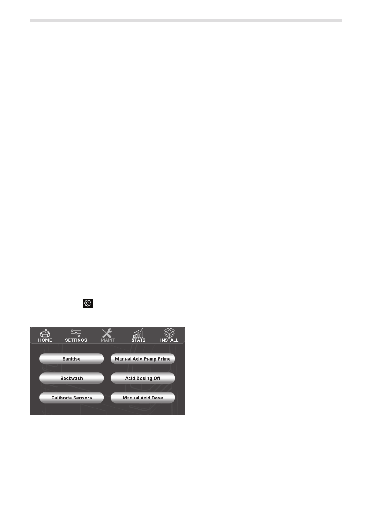
From the “Home”screen of the Halo Chlorinator, press
the “Settings” icon and then press the “Maint” icon
to display the maintenance page. See Figure 11.
Figure 11. Halo Maintenance Screen
“Manual Acid Pump Prime” will run the acid dosing
pump for 30 seconds to help prime the pump.
(Repeatas necessary.)
“Acid Dosing Off” can be used to turn the acid
dosing off for a period from 1 minute to 24 hours
(orindefinitely).
– When adding some chemicals (e.g. pH buffer /
sodium bicarbonate) it is desirable to turn the
acid dosing off for up to 24 hours.
– If your drum has run out of acid it is desirable
to disable acid dosing “indefinitely” until the
drum is refilled. To resume acid dosing, you
need to return to the“Acid Dosing Off” page
toresume dosing.
“Manual Acid Dose” can be used to add a specific
amount of acid to your pool (e.g. If your pool shop
advises you to add X litres of acid). From this screen,
you can also choose what mode the chlorinator
should be in after dosing the acid. (Typically you
would resume in auto mode, however if a large
amount of acid was added you may choose manual
mode and change to auto later.)
4.3 Operation Via the Halo ChlorGo App
The Halo ChlorGo App can be used to set the pH or
acid level using the “Settings” icon.
The only manual operation that can be performed
from the app however is to disable the dosing for a
period or indefinitely (and to reinstate dosing that
hasbeen turned off).

10
HALO®DOSER™installation manual
Section 5. Regular Maintenance
Caution: ACID leaks can be harmful to other equipment and to users. Appropriate protective equipment should be worn
when handling acid and performing any repairs
The Halo Doser should be inspected periodically to ensure that there are no leaks from any tubes.
If any leaks are detected check if the fittings can be tightened, otherwise the tubing should be replaced.
To inspect the “squeeze tube” for leaks, first remove the clear cover and then the blue cover (squeeze on the tabs
on the sides of the blue cover). This will expose the internal pump mechanism. If there is a leak in the “squeeze
tube”, then the blue cover/squeeze tube assembly should be replaced (Part # 1116096).
Section 6. Troubleshooting
PROBLEM SOLUTION
The pools pH level is rising
above the set level
• Check that the acid drum isn’t empty.
• Check that the tube going into the acid drum goes to the bottom of the drum.
• Check that there are no leaks when the filter pump is running.
• Check that the acid pump rotates during manual dosing.
• Check that there are no leaks during manual dosing.
• Manually dose acid and recheck the pH.
• Check that the acid injection point isn’t blocked.
The acid pump doesn’t seem
to rotate
• In automatic mode the pump only rotates when it senses that it needs to. Even in
these circumstances it may come on for only 3 seconds every 12 minutes.
• To check for rotation, use the manual dose option in the maintenance menu.
(See"Manual Acid Dose" in Section 4.2).
Water returns to the
chemical drum
• Check for any damage to the squeeze tube, and if the white rigid tube in the acid
drum has any splitting.
• Ensure non-return valve is installed in the right direction, or if faulty replace as
required.

11
HALO®DOSER™Installation Manual
NOTES

H0740100_REVA
©2021 Fluidra S.A. All rights reserved. This document is subject to change without notice.©2021 Fluidra S.A. All rights reserved. This document is subject to change without notice.
Fluidra Group Australia Pty Ltd
219 Woodpark Road
Smithfield NSW 2164, Australia
1 300 186 875
AstralPool.com.au
Table of contents
Other Astral Pool Control Unit manuals

Astral Pool
Astral Pool POOL BASIC User manual

Astral Pool
Astral Pool CONTROL BASIC User manual

Astral Pool
Astral Pool HALO XPAND User manual

Astral Pool
Astral Pool 28512 Instruction manual

Astral Pool
Astral Pool VRAC III Basic Series Manual

Astral Pool
Astral Pool CONTROL BASIC PLUS User manual

Astral Pool
Astral Pool 28512 User manual

Astral Pool
Astral Pool System VRAC Basic Manual