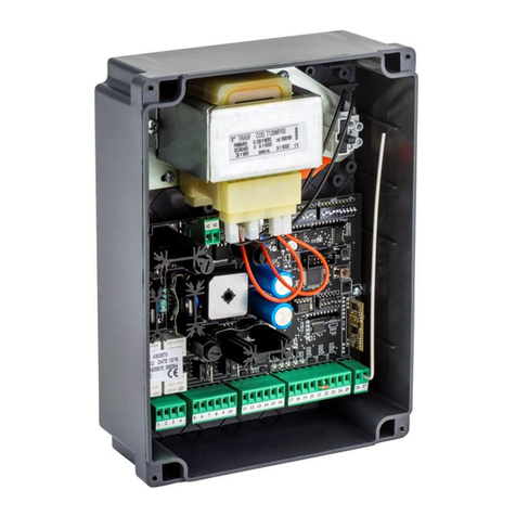
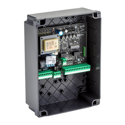
GiBiDi AS06200 Guide

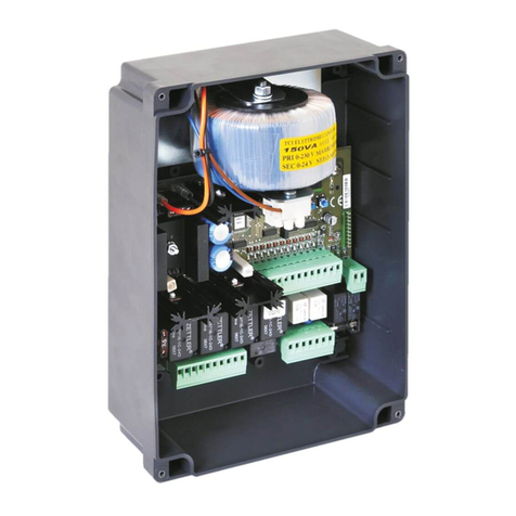
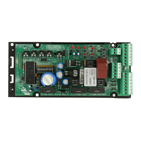
BR24
Electronic control unit
INSTRUCTIONS FOR INSTALLATION
BR24 - (AS06200)
UK

BR24 BR24
2 3
SCHEMA ELETTRICO / ELECTRICAL CONNECTION
1
LED STATUS
ON
OFF
OPEN
START
STOP
CLOSE
FCC
SAFETY
PHOTO
COM
SYNC
OPT1
COM
FCA
JP7
JP8
RISERVA
+ACC +24Vcc
0Vcc
24 25 26 27 28 29 30 31 32 33 34 35 36 37
JP1
24Vcc 10W MAX
24Vcc 3W MAX
+ 24Vcc
0Vcc
230Vac ~
230Vac ~
LAMP
LAMP
SW1 SW2 SW3 SW4
LCD1
DL1
DL2
DL6
DL3
DL4
DL5
DL7
DL8
DL9
DL10
M
MOTOR
MOTOR
JP3 JP4 JP5 JP6
PHASE
COM
COM
SPIA
LIGHT
NC
NC
COM
LIGHT
NO
NO
+ SAF
NEUTRAL
COM
OPT2
JP2
RL6
RL4
RL5
RL1
RL3RL2
F2
F1
BR24
D1
CF2 CF3 CF1
F3
0Vac
24Vac
+ SK
- SK
(AS05020)
CB24
~ 230Vac
24Vac
0Vac
6/12Vac
JP2
SYNC STOP START
RX
1 2 3 4 5 6 7 8 9 13 16 1910 14 17 2011 15
JP13
SLOW
SLOW
38 39
18 2112 22 23
OPEN
START
STOP
CLOSE
FCC
SAFETY
PHOTO
COM
SYNC
OPT1
COM
FCA
JP7 JP8
RISERVA
+ACC
24 25 26 27 28 29 30 31 32 33 34 35 36 37
FIG. 8
FIG. 9
FIG. 7
SINCRONISMO / SYNCRONISM
2
BR24 MASTER
BR24 SLAVE
19 20 21 22 23
SPIA
SPIA
24Vcc 3W MAX
+24Vcc
0Vcc
+ SAF
COM
OPT2
34 35 36 37
+24Vcc
SYNC
ACC.
COM
OPT1
34 35 36 37
SYNC
COM
OPT1
JP6 JP8
JP8
13 14 15
COM
NC
NO
JP4
16 17 18
COM
NC
NO
JP5
27 28 29 30 31 32 3324 25 26
STOP
CLOSE
FCC
SAFETY
PHOTO
FCA
START
OPEN
COM
RISERVA
JP7
38 39
SLOW
SLOW
JP13
38 39
SLOW
SLOW
JP13
19 20 21 22 23
SPIA
SPIA
+ SAF
COM
OPT2
JP6
16 17 18
COM
NC
NO
JP5
13 14 15
COM
NC
NO
JP4JP1
MOTOR
CLOSE
MOTOR
OPEN
0Vac
24Vac
24Vcc 10W MAX
LAMP
LAMP
M
SK
SK
4 5 6 7 81 2 3
JP1
MOTOR
CLOSE
MOTOR
OPEN
0Vac
24Vac
24Vcc 10W MAX
LAMP
LAMP
M
SK
SK
4 5 6 7 81 2 3
START
27 28 29 30 31 32 3324 25 26
STOP
CLOSE
FCC
SAFETY
PHOTO
FCA
OPEN
COM
RISERVA
JP7
JP3
910 11 12
NEUTRAL
230 Vac
PHASE
230 Vac
LIGHT
LIGHT
910 11 12
NEUTRAL
230 Vac
PHASE
230 Vac
LIGHT
LIGHT
JP3
FIG. 8
FIG. 9
FIG. 7 FIG. 8
FIG. 9
FIG. 7

BR24 BR24
2 3
SCHEMA ELETTRICO / ELECTRICAL CONNECTION
1
LED STATUS
ON
OFF
OPEN
START
STOP
CLOSE
FCC
SAFETY
PHOTO
COM
SYNC
OPT1
COM
FCA
JP7
JP8
RISERVA
+ACC +24Vcc
0Vcc
24 25 26 27 28 29 30 31 32 33 34 35 36 37
JP1
24Vcc 10W MAX
24Vcc 3W MAX
+ 24Vcc
0Vcc
230Vac ~
230Vac ~
LAMP
LAMP
SW1 SW2 SW3 SW4
LCD1
DL1
DL2
DL6
DL3
DL4
DL5
DL7
DL8
DL9
DL10
M
MOTOR
MOTOR
JP3 JP4 JP5 JP6
PHASE
COM
COM
SPIA
LIGHT
NC
NC
COM
LIGHT
NO
NO
+ SAF
NEUTRAL
COM
OPT2
JP2
RL6
RL4
RL5
RL1
RL3RL2
F2
F1
BR24
D1
CF2 CF3 CF1
F3
0Vac
24Vac
+ SK
- SK
(AS05020)
CB24
~ 230Vac
24Vac
0Vac
6/12Vac
JP2
SYNC STOP START
RX
1 2 3 4 5 6 7 8 9 13 16 1910 14 17 2011 15
JP13
SLOW
SLOW
38 39
18 2112 22 23
OPEN
START
STOP
CLOSE
FCC
SAFETY
PHOTO
COM
SYNC
OPT1
COM
FCA
JP7 JP8
RISERVA
+ACC
24 25 26 27 28 29 30 31 32 33 34 35 36 37
FIG. 8
FIG. 9
FIG. 7
SINCRONISMO / SYNCRONISM
2
BR24
MASTER
BR24
SLAVE
19 20 21 22 23
SPIA
SPIA
24Vcc 3W MAX
+24Vcc
0Vcc
+ SAF
COM
OPT2
34 35 36 37
+24Vcc
SYNC
A CC.
COM
OPT1
34 35 36 37
SYNC
COM
OPT1
JP6 JP8
JP8
13 14 15
COM
NC
NO
JP4
16 17 18
COM
NC
NO
JP5
27 28 29 30 31 32 3324 25 26
STOP
CLOSE
FCC
SAFETY
PHOTO
FCA
START
OPEN
COM
RISERVA
JP7
38 39
SLOW
SLOW
JP13
38 39
SLOW
SLOW
JP13
19 20 21 22 23
SPIA
SPIA
+ SAF
COM
OPT2
JP6
16 17 18
COM
NC
NO
JP5
13 14 15
COM
NC
NO
JP4JP1
MOTOR
CLOSE
MOTOR
OPEN
0Vac
24Vac
24Vcc 10W MAX
LAMP
LAMP
M
SK
SK
4 5 6 7 81 2 3
JP1
MOTOR
CLOSE
MOTOR
OPEN
0Vac
24Vac
24Vcc 10W MAX
LAMP
LAMP
M
SK
SK
4 5 6 7 81 2 3
START
27 28 29 30 31 32 3324 25 26
STOP
CLOSE
FCC
SAFETY
PHOTO
FCA
OPEN
COM
RISERVA
JP7
JP3
910 11 12
NEUTRAL
230 Vac
PHASE
230 Vac
LIGHT
LIGHT
910 11 12
NEUTRAL
230 Vac
PHASE
230 Vac
LIGHT
LIGHT
JP3
FIG. 8
FIG. 9
FIG. 7 FIG. 8
FIG. 9
FIG. 7

4 5
BR24 BR24
COLLEGAMENTO BATTERIE CON SINCRONISMO /
BATTERY BACKUP CONNECTION WITH SYNCRONISM
3
BR24
MASTER
BR24
SLAVE
19 20 21 22 23
SPIA
SPIA
24Vcc 3W MAX
+24Vcc
0Vcc
+ SAF
COM
OPT2
34 35 36 37
+24Vcc
SYNC
A CC.
COM
OPT1
34 35 36 37
SYNC
COM
OPT1
JP6 JP8
JP8
13 14 15
COM
NC
NO
JP4
16 17 18
COM
NC
NO
JP5
27 28 29 30 31 32 3324 25 26
STOP
CLOSE
FCC
SAFETY
PHOTO
FCA
START
OPEN
COM
RISERVA
JP7
38 39
SLOW
SLOW
JP13
38 39
SLOW
SLOW
JP13
19 20 21 22 23
SPIA
SPIA
+ SAF
COM
OPT2
JP6
16 17 18
COM
NC
NO
JP5
13 14 15
COM
NC
NO
JP4JP1
MOTOR
CLOSE
MOTOR
OPEN
0Vac
24Vac
24Vcc 10W MAX
LAMP
LAMP
M
SK
SK
4 5 6 7 81 2 3
JP1
MOTOR
CLOSE
MOTOR
OPEN
0Vac
24Vac
24Vcc 10W MAX
LAMP
LAMP
M
SK
SK
4 5 6 7 81 2 3
START
27 28 29 30 31 32 3324 25 26
STOP
CLOSE
FCC
SAFETY
PHOTO
FCA
OPEN
COM
RISERVA
JP7
JP3
910 11 12
NEUTRAL
230 Vac
PHASE
230 Vac
LIGHT
LIGHT
910 11 12
NEUTRAL
230 Vac
PHASE
230 Vac
LIGHT
LIGHT
JP3
FIG. 8
FIG. 9
FIG. 7 FIG. 8
FIG. 9
FIG. 7
CB24 CB24
COLLEGAMENTO COSTA / SAFETY DEVICE CONNECTION
RISERVA
COM
JP3
32 33
OROLOGIO ESTERNO
EXTERNAL CLOCK
NA NC
COM
7
8
9
SEMAFORO DUE VIE / TWO WAYS TRAFFIC LIGHT
6
JP4 JP5
ROSSO/RED
ELECTRICAL BOX
VERDE/GREEN
INGRESSO/IN
230Vac/24Vac-dc
ROSSO/RED VERDE/GREEN
USCITA/OUT
13 14 15
COM
NC
NO
17 18
COM
NC
NO
16
SEMAFORO UNA VIA /
ONE WAY TRAFFIC LIGHT
OROLOGIO ESTERNO /
EXTERNAL CLOCK
54
JP5
16 17 18
COM
NC
NO
ROSSO
RED
ELECTRICAL BOX
VERDE
GREEN
230Vac/24Vac-dc
SENZA BORDO SENSIBILE
WITHOUT CONDUCTIVE EDGE
8K2
30
33
BORDO SENSIBILE CON RESISTENZA 8K2 INTEGRATA
CONDUCTIVE EDGE WITH RESISTANCE 8K2 INTEGRATED
30
33
BORDO SENSIBILE CON CONTATTO N.C.
CONDUCTIVE EDGE WITH N.C. CONTACT
30
33
8K2

6 7
BR24 BR24
COLLEGAMENTO FOTOCELLULE / PHOTOCELLS CONNECTION
10
11
PHOTO
COM
COM
+ACC
JP7 JP8
31 34
33 36
RX
1 3 42
AC
B
J4
J2 J3
M2
TX
1 32
J1
M1
RX
1 3 42
AC
B
J4
J2 J3
M2
TX
1 32
J1
M1
PHOTO
COM
COM
+ACC
JP7 JP8
31 34
33 36
1
1
3
3
4
4
2
2
TX
TX
1
1
3
3
4
4
5
5
2
2
RX
RX
FOTO TEST / PHOTO TEST
12
13
PHOTO
COM
COM
+ACC
JP7 JP8
31 34
33 3621 22
+SAF
COM
RX
1 3 42
AC
B
J4
J2 J3
M2
TX
1 32
J1
M1
JP6
RX
1 3 42
AC
B
J4
J2 J3
M2
TX
1 32
J1
M1
PHOTO
COM
COM
+ACC
JP7 JP8
31 34
33 3621 22
+SAF
COM
JP6
1
1
3
3
4
4
2
2
TX
TX
1
1
3
3
4
4
5
5
2
2
RX
RX

34 BR24 35
BR24
UK
READ CAREFULLY THESE INSTRUCTIONS BEFORE PROCEEDING WITH INSTALLATION.
Thank you for choosing GI.BI.DI.
WARNING: IMPORTANT SAFETY INSTRUCTIONS.
It is important for the safety of persons to follow these instructions.
Keep this instructions manual.
WARNINGS:
This product has been tested by GI.BI.DI. for full compliance with the requirements of the directives in force. GI.BI.DI. S.r.l. reserves
the right to change the technical data without prior notice in relation to product development.
DISPOSAL: GI.BI.DI. advises recycling the plastic components and to dispose of them at special
authorised centres for electronic components thus protecting the environment from polluting substances.
UK
TECHNICAL SPECIFICATIONS / FUNCTIONS
• Red leds of NC contacts. There is not the safety devices led. See “SIGNALLING LEDS” table.
• Green / yellow leds of NO contacts. See “SIGNALLING LEDS” table.
• Management of 2 control units synchronized between them.
• Management of 1 electric lock or electromagnet.
• Management of courtesy light.
• Management of 230 Vac boom lights
• Management of traffic light.
• Enabling the photocell test done before the opening and closing movement.
• Enabling the test of the amperometric circuit and conductive edge 8k2 done before the opening and closinG
movement.
• Stop and motion inversion for 1 s after safety devices intervention . At the next START pulse, the motion
restarts in the obstacle freeing direction.
• Separate safety devices power supply. Connect to this terminals the safety devices that will be tested.
• Double reading of the limit switch always active, except in dead man operating logic.
• Decelerations always active except in dead man operating logic.
• Working time in opening and closing fixed at 10 sec.
• Deceleration time in opening and closing fixed at 10 sec.
• Motor power fixed at 10 level.
• Digital programming of all functions.
• Adjustable pause time.
• Deceleration speed that can be selected between adjustable mode on 10 levels (with terminal block JP13
open) or fixed mode by secondary transformer (green or red cable on faston CF1).
• Control of current absorption (anti-crushing) adjustable on 100 levels both in thrust phase and in deceleration
phase.
• 4 operating logics: step by step with stop, step by step, condominium or automatic, dead man.
• Anti-crushing enabling only in closing (motion inversion for 1 second and locking) or amperometric detection for
limit switch active both in opening and closing.
• Programming of: automatic closing, fast closing, preflashing, fixed or intermittent flashing light, management of
an external clock with 3 different modes, cycles number for planned maintenance, installer code, number of
cycles done, number of powered days.
INSTALLATION WARNINGS
• Before proceeding with the installation, fit a magneto-thermal or differential switch with a maximum capacity of
10A upstream of the system. The switch must guarantee omnipolar separation of the contacts, with an opening
distance of at least 3 mm.
• To prevent possible interferences, differentiate and always keep the power cables (minimum cross-section
1,5mm²) separate from the signal cables (minimum cross-section 0,5mm²).
• Make the connections referring to the following tables and to the attached screen-print. Be extremely careful to
connect in series all the devices that must be connected to the same N.C. (normally closed) input and in
parallel all the devices that share the same N.O. (normally open) input. Incorrect installation or improper use of
the product may compromise system safety.
• Keep all the materials contained in the packaging away from children, since they pose a potential risk.
• The manufacturer declines all responsibility for improper functioning of the automated device, if the original
components and accessories suitable for the specific automation are not used.
• At the end of the installation, always check carefully the proper functioning of the system and devices used.
• This instruction manual addresses people qualified for the installation of “live equipment”. Therefore good
technical knowledge and professional practice in compliance with the regulations in force are required.
• Maintenance must be carry out by qualified personnel.
• Before carrying out any cleaning or maintenance operation, disconnect the control unit from the mains.
• This control unit may only be used for the purpose for which it was designed. Check the aim of the final use
and be sure to take all the necessary safeties.
• Use of the products for purposes different from the intended use has not been tested by the manufacturer,
therefore any work is carried out on full responsibility of the installer.
• Mark the automated gate with visible warning plates.
• Warn the user that children and animals may not play or stand around near the gate.
• Appropriately protect the dangerous points (for example, use a conductive edge).
• The control unit does not assure by it self the safety against crushing. Be sure that the safety devices
connected to the control unit are fit for purpose.
WARNINGS FOR THE USER
• In the event of an operating fault or failure, cut the power upstream of the control unit and call the Technical
Service.
• Periodically check the functioning of the safety devices. Any repairs must be carry out by specialised personnel
using original and certified materials.
• The appliance is not to be used by children or people with reduced physical, sensory or mental capabilities, or
lack of experience and knowledge, unless they have been given supervision or instruction.
• Do not touch the card for adjustments and/or maintenance.

36 BR24 37
BR24
UK UK
ELECTRICAL CONNECTIONS: FASTON
Cable colour
GREEN
RED
YELLOW
BLACK
Terminal
CF1
CF2
CF3
Description
Deceleration 12 Vac. During the deceleration phase the motor will be powered with
12 Vdc voltage. See the relevant paragraph
Deceleration 6 Vac. During the deceleration phase the motor will be powered with
6 Vdc voltage. See the relevant paragraph
Central power supply 24 Vac
Central power supply 0 Vac
Description
JP1
JP3
JP4
JP5
Terminal
Battery charger card connection
1
Position Signal
0Vac
Battery charger card connection
224Vac
Battery charger card connection
POWER SUPPLY PHASE 230Vac for boom lights
On this terminal block there is a free contact that is activated at the start of the motor and disabled after 3 s.
The contact can be used to control an ELECTRIC LOCK or an ELECTROMAGNET.
The free contact does not provide any power supply, so it allows the use of 24 Vdc or 230 Vac devices,
supplying them with the right cabling.
WARNING: in case of connection of a double way traffic light, this function will not be available any more.
On this terminal block there is a free contact that is activated at the start of the motor and disabled 3 minutes
after the end of the motion. The contact can be used to control a COURTESY LIGHT or an ELECTROMAGNET.
The free contact does not provide any power supply, so it allows the use of 24 Vdc or 230 Vac devices,
supplying them with the right cabling.
WARNING: in case of connection of a single or double way traffic light, this function will not be available
anymore.
3
9
+SK
L
ELECTRICAL CONNECTIONS: TERMINAL BLOCKS
4
10
13
5
11
14
6
12
15
7
8
-SK
LIGHT
COM
M1
LIGHT
NC
M1
N
NO
LAMP
LAMP
Battery charger card connection
BOOM LIGHTS 230 Vac
COMMON
Barrier motor power supply
BOOM LIGHTS 230 Vac
CONTACT NORMALLY CLOSED
Barrier motor power supply
POWER SUPPLY NEUTRAL 230Vac for boom lights
CONTACT NORMALLY OPEN
Flashing light output 24Vdc 10W max. Operation:
slow flashing in opening,
off in pause,
fast flashing in closing
Flashing light output 24Vdc 10W max.
16
17
18
COM
NC
NO
COMMON
CONTACT NORMALLY CLOSED
CONTACT NORMALLY OPEN
TECHNICAL DATA
BR24 / AS06200
Electronic control unit
for the automation of a 24 Vdc barrier
230Vac monophase 50/60 Hz
1
24 Vdc
24Vdc 10W max
230Vac 3W max
24Vdc - 230Vac free relay contact
24Vdc 3W max
24Vdc 8W max including accessories power supply
Plug-in
-20°C +60°C
24Vdc 8W max including safety devices power supply
Control unit
Type
Power supply
No. Motors
Motor power supply
Flashing light
Boom lights
Courtesy light
Electromagnet / Electric lock
Warning light
Safety devices power supply
Radio receiver
Operating temperature
Accessories power supply
JP6
JP7
19
20
SPIA
SPIA
Warning light output 24 Vdc 3W max (+) Operation:
slow flashing in opening,
fixed light in pause,
fast flashing in closing
Warning light output 24 Vdc 3W max (-)
21
28
22
29
24
26
27
25
23
+ SAF
FCA
COM
FCC
START
CLOSE
STOP
OPEN
OPT 2
Power supply 24 Vdc photocell transmitter for test
OPENING LIMIT SWITCH input (N.C.)
COMMON INPUT-OUTPUT
CLOSING LIMIT SWITCH input (N.C.)
START input (N.O.)
Control the operation cycle of the barrier
CLOSING (N.O.) input.
Determine only the closing of the barrier
STOP (N.C.) input
Determines the lock of the manoeuvre
If not used, jump with terminal 33 (COM)
OPENING input (N.O.).
Determine only the opening of the barrier.
WARNING: The OPEN command changes his functioning if a traffic light is connected
and menu E20-3 is selected.
Refer to the paragraph about traffic light operation
SYNCHRONISM CONNECTION.
Refer to paragraph “SYNCRONIZED SYSTEM” and figure 2

38 BR24 39
BR24
UK
34
35
JP7
JP8
+ ACC
SYNC
EXTERNAL ACCESSORIES POWER SUPPLY +24 Vdc
SYNCRONISM CONNECTION
Refer to paragraph “SYNCRONIZED SYSTEM” and figure 2
33
30
31
32
COM
SAFETY
PHOTO
RESERVE
COMMON INPUT-OUTPUT
PHOTOCELL input (N.C.).
If not use disable during programming
Operation:
Input active only during closing.
It stops and inverts the motion, opening the barrier completely.
If the barrier is closed, it does not affect its functioning.
If intercepted during pause, it reloads the pause time.
SAFETY DEVICES input (8K2 EDGE)
If not in use disable during programming (C9-1).
If using a safety edge with NC contact, an 8K2 resistor must be connected in
series to one of the cables wired to the control board.
Operation:
Input active only during closing. stop the motion and open.
The barrier will remain blocked until next command.
The barrier will
Multifunctional input EXTERNAL CLOCK: see
programming menu E9
37
36
OPT1
COM
SYNCRONISM CONNECTION
EXTERNAL ACCESSORIES POWER SUPPLY and SYNCRONISM CONNECTION
Refer to paragraph “SYNCRONIZED SYSTEM” and figure 2
UK
38
40
39
41
JP13
JP12
JP2
SLOW
GND
SLOW
ANT
Plug in radio receiver connector
SLOW DOWN See paragraph
“SLOW DOWN SPEED”
Not mounted
SLOW DOWN
Description
Description
Position
Position
Colour
Value
Signal
Type
Lights when the START command is activated and turns off immediately after
External accessories protection (accessories wired between +24 Vdc and COMMON)
Control unit, motor and accessories protection when the control unit is battery supplied
Control unit, motor and accessories protection
Lights when the OPEN command is activated and turns off immediately after
Always on. It turns off when the STOP command is activated
Always on. It turns off when reaching the OPENING LIMIT SWITCH
Always on. It turns off when reaching the CLOSING LIMIT SWITCH
Lights when the CLOSE command is activated and turns off immediately after
Always on. It turns off when the photocell is intercepted
Always on. It shows logic circuit power supply
Lights when the contact switch from open to close and remain on until the contact
switch off.
Lights on SLAVE board when an opening command is done in syncronized system
DL1
F1
F2
F3
DL2
DL3
DL4
DL5
DL6
DL7
DL9
DL8
DL10
GREEN
500 mA
15 A
15 A
GREEN
RED
RED
RED
YELLOW
RED
GREEN
RED
YELLOW
START
FAST
/
/
OPEN
STOP
FCA
FCC
CLOSE
PH1
VCC
RESERVE
OPTIONAL
SIGNALLING LED
PROTECTION FUSES
Signal
PHOTOCELL
SAFETY EDGE
LIMIT SWITCH
STOP
Open contact Closed contact
CHECK ENABLED INPUT
During stand by (closed barrier) the control unit perform a test to verify the consistency between the enabling of
an input by the menu and the status of the relevant contact.
The letter on top left of the display could be “m” if the control unit is set as MASTER or “o” if set as SLAVE.
WARNING: The display indication is not a verification of the correct functionality of the input but simply
a check on what is enabled by the menu and the input status.
If the menu related to one input is disabled there will not be any check and the display indication will be
the one shown in the “Closed contact” column.
m
F _ _ _m
m
C m F
m
Lm F _
m
Sm F _ _
m
_m
m
_m F
m
m _ _ _
m
_m _ _ _

40 BR24 41
BR24
UK UK
PASSWORD MANAGEMENT
You can enter the control board programming menu in 2 different ways, using 2 different password depending on
which menu you want to set.
BASIC MODE: when prompted for the password enter 0000. In such a way you enter only the menus listed
below
A3 operation logic
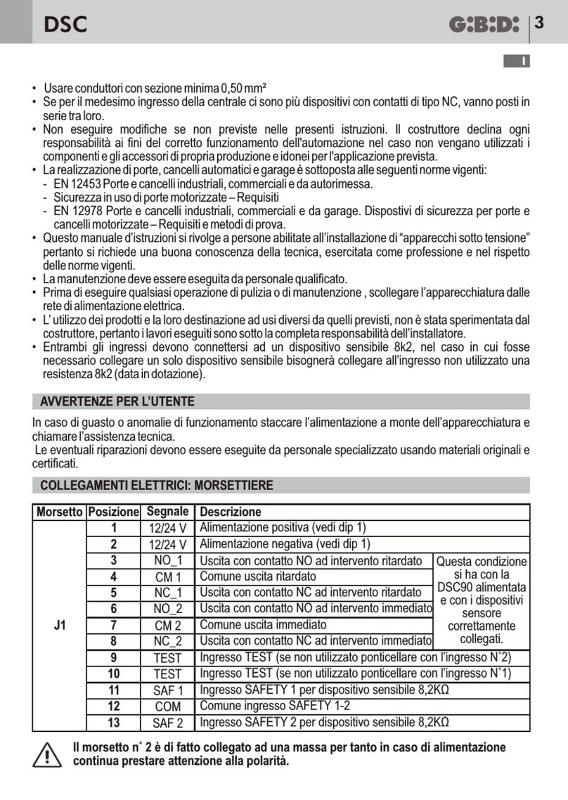
A5 automatic closing
C9 safety edge
H9 pause time
E94 firmware release
ADVANCED MODE: when prompted for the password enter the default one 1234 . In such a way you enter all
the menus.
WARNING: if you change the password in the menu E92, that is if you change the default password 1234
with another one, then you can no more access the system by entering 0000. The only way to do that is
by resetting the control board or by entering again the password 1234 in the menu E92.
MENU
ESC- OK +
PASS
ESC- OK +
0 0 0 0
ESC- OK +
Press ESC and OK button simultaneously for 3 s.
At the same time will appear MENU on the display.
After 3 s appears PASS on the display.
Press the OK button to continue with the procedure.
Press and hold the ESC key for 3 s to exit and return to previous point.
The message EXIT will appear on the display.
It appears on the display 4 digits ( 0 0 0 0 ) with the former of them
flashing.
If you want to enter the ADVANCED programming, by means of + or -
keys type the first digit of the installer code set in the menu E92.
Once you get to the desired digit confirm with the OK button and go to
the next step.
If you want to enter the BASIC programming, confirm the digit 0
WARNING !
At first use of the control board the default PASSWORD set in the
menu E92 is: 1234
Change the value of menu E92 only after having completed the settings
of the menus A C F H E.
ENTERING PASSWORD PROCEDURE
0 0 0 0
ESC- OK +
The third digit blinks.
If you want to enter the ADVANCED programming, by means of + or -
keys type the third digit of the installer code set in the menu E92.
Once you get to the desired digit confirm with the OK button and go to
the next step.
If you want to enter the BASIC programming, confirm the digit 0
The ESC button will move the flashing digit to the left until the first digit.
0 0 0 0
ESC- OK +
The second digit blinks.
If you want to enter the ADVANCED programming, by means of + or -
keys type the second digit of the installer code set in the menu E92.
Once you get to the desired digit confirm with the OK button and go to
the next step.
If you want to enter the BASIC programming, confirm the digit 0
The ESC button will move the flashing digit to the left until the first digit.
0 0 0 0
0 0 0 0
A C F H E
_ _ _ _ _
ESC
ESC
ESC
ESC
-
-
-
-
OK
OK
OK
OK
+
+
+
+
The fourth digit blinks.
If you want to enter the ADVANCED programming, by means of + or -
keys type the fourth digit of the installer code set in the menu E92.
Once you get to the desired digit confirm with the OK button and go
to the next step.
If you want to enter the BASIC programming, confirm the digit 0
The ESC button will move the flashing digit to the left until the first digit.
By now the installer code is completed: if it is right you go to the next step.
If the installer code is wrong the message PASS appears again
Proceed with the programming of the menus following the instructions
in the relevant paragraphs.
Once the programming is completed press and hold for 3 s the ESC
button to store the settings and exit from programming procedure.
Simultaneously appears the message EXIT
If there is no mismatch between enabling and input status appears the
screen you can see here beside, otherwise it will appear an indication
of which input has a fault.
Refer to the paragraph “CHECK ENABLED INPUT”
In this case the buttons + and OK will mean:
+ Z START OK STOPZ

42 BR24 43
BR24
UK UK
A C F H E
A 3 4
ESC
ESC
-
-
OK
OK
+
+
When the display shows the main menus (letters ACFHE or just some
of them depending on which password was used to access
programming) let the letter A blink by moving to the right or to the left
with the buttons + or -
Once the letter A blinks confirm with the OK button
By means of + or - buttons you can select the submenus (A3, A5)
The digits on the lcd are fixed to show that is no possible any modification.
The button ESC lets you to go to the upper level (menus A, C, F, H E).
With OK button you enter the selected menu and the digits start blinking to
show that is now possible to modify the values and the ESC button becomes
irrelevant.
Right now with + e - buttons you can change the settings of the selected
menu. With the OK button you confirm the data and return to the selected
menu with fixed digits.
Example Programming MENU A
MENU A: SYSTEM CONFIGURATION AND OPERATING LOGIC SELECTION
A 5 2
ESC- OK +
Right now with + and - buttons you can scroll the other submenus
of the menu A and you can follow the same procedure shown above.
The ESC button lets you to go to the upper level (menus A, C, F, H E).
Description MENU A
Menu
A3
Function
STEP BY STEP
WITH STOP LOGIC
Status
2
Description
It enables the STEP BY STEP WITH STOP logic
Operation:
Command START
START → open
Next START → stop (*)
Next START → close
Next START → open
If automatic closing has been activated (menu A5) and the opening
phase is at the end of the cycle, when the pause time has elapsed
(menu H9), the control unit automatically closes the gate.
If the gate is open “START” closes the gate.
(*) If syncronized system this command is not sent from MASTER to
SLAVE.
Command OPEN
- With gate closed it opens but does not make the automatic closing
- During opening is irrelevant
- During pause is irrelevant
- During closing inverts the motion toward opening and it will not follow
an automatic closing.
A3 STEP BY STEP
WITH STOP LOGIC 2
WARNING: the OPEN command changes its function if you use a
traffic light and select the menu E20-3.
Refer to the paragraph related to the traffic light operation
Command CLOSE
- During opening inverts the motion toward closing
- During pause enables closing
- Durino closing is irrelevant
- With gate closed is irrelevant
A3 STEP - STEP
LOGIC 3
It enables the STEP - STEP logic
Comando START
START → open
Next START → close (*)
Next START → open
If automatic closing has been activated (menu A5) and the opening
phase is at the end of the cycle, when the pause time has elapsed
(menu H9), the control unit automatically closes the gate.
If the gate is open “START” closes the gate.
(*) If syncronized system this command is not sent from MASTER
to SLAVE.
Operation:
Command OPEN
- With gate closed it opens but does not make the automatic closing
- During opening is irrelevant
- During pause is irrelevant
- During closing inverts the motion toward opening and it will not follow
an automatic closing.
WARNING: the OPEN command changes its function if you use a traffic
light and select the menu E20-3.
Refer to the paragraph related to the traffic light operation
Command CLOSE
- During opening inverts the motion toward closing
- During pause enables closing
- During closing is irrelevant
- With gate closed is irrelevant
A3
AUTOMATIC /
CONDOMINUM
LOGIC
4
It enables the AUTOMATIC/CONDOMINIUM logic
Operation:
Command START
START → open
Next START(S) → irrelevant if the system is opening, or it reset the
pause time (if the gate is in pause and the automatic closing is
activated).
When the pause time has elapsed:
If the automatic closing is activated, the system closes automatically.
If the automatic closing is not activated, a START command close the
gate.
In closing a START command opens.

44 BR24 45
BR24
UK UK
A3
AUTOMATIC /
CONDOMINUM
LOGIC
4
Command OPEN
- With gate closed it opens but does not make the automatic closing
- During opening is irrelevant
- During pause is irrelevant
- During closing inverts the motion toward opening and it will not follow
an automatic closing.
WARNING: the OPEN command changes its function if you use a traffic
light and select the menu E20-3.
Refer to the paragraph related to the traffic light operation
Command CLOSE
- During opening inverts the motion toward closing
- During pause enables closing
- Durino closing is irrelevant
- With gate closed is irrelevant
A3 DEAD MAN
LOGIC 5
It enables the DEAD MAN logic
Operation:
OPEN button → opens only if the button is held down.
CLOSE button → closes only if the button is held down.
START command is irrelevant.
With Dead Man Logic the button + (START) and OK (STOP) on the
control board are irrelevant.
With the movement the electromagnet and the courtesy light will turn on.
With dead man logic the opening and closing movement will stop
always on the first limit switch.
The slow down are never active.
The safety devices are never active.
It is just possible the regulation of the AMPEROMETRIC THRESHOLD
of the motor.
If the buttons will be continuously pressed the flashing light and the
warning light remain active even if the motors has stopped on the limit
switches.
With this logic is not possible to make a syncronized system.
A5 AUTOMATIC CLOSING 1
2
Disables the automatic closing
Enables the automatic closing
A C F H E
ESC- OK +
When the display shows the main menus (letters ACFHE or just some
of them depending on which password was used to access
programming) let the letter C blink by moving to the right or to the left
with the buttons + or -
Once the letter C blinks confirm with the OK button
Example Programming MENU C
MENU C: FUNCTION SELECTIONI
C 1 1
C 2 2
ESC
ESC
-
-
OK
OK
+
+
By means of + or - buttons you can select the submenus (C1, C2, C3,..)
The digits on the lcd are fixed to show that is no possible any modification.
The button ESC lets you to go to the upper level (menus A, C, F, H E).
With OK button you enter the selected menu and the digits start blinking
to show that is now possible to modify the values and the ESC button
becomes irrelevant.
Right now with + e - buttons you can change the settings of the selected
menu.
With the OK button you confirm the data and return to the selected menu
with fixed digits.
Right now with + and - buttons you can scroll the other submenus of
the menu C and you can follow the same procedure shown above.
The ESC button lets you to go to the upper level (menus A, C, F, H E).
Description MENU C
Menu
C1
C2
Function
FAST CLOSING
FLASHING LIGHT
Status
1
2
3
2
Description
Disables the fast closing function
Blinking flashing light output
Fixed flashing light output
Enables fast closing function
Reduces the pause time to 3 s following interception and subsequent
freeing of the photocells.
C3 PREFLASHING 1
2
Disables preflashing.
The flashing light and the motors start at the same time.
Enables 3 s preflashing before motor start
C5 SLOWED
OPENING / CLOSING
2
Disabled
Operation:
The manoeuvre starts and the motor runs at full speed.
The intervention of the first closing limit switch starts the deceleration.
The deceleration is made with the transformer when JP13 is closed
with a wire. The deceleration is made electronically adjustable when
JP13 is open with no wire.
The deceleration speed can be adjusted via parameter F2 if JP13 is open
with no wire . The intervention of the second closing limit switch causes
the end of the motion
6
Enabled in closing. (suggested for booms over 4m)
Operation:
The closing manoeuvre starts with slowed motion, in this phase the
slow down is obtained by the transformer.
In correspondence of the first closing limit switch the slow down made
with the transformer (JP13 closed with wire) or the adjustable
electronic slow down (JP13 open) starts.
The intervention of the second closing limit switch causes the end
of the motion.

46 BR24 47
BR24
UK UK
C5 SLOWED
OPENING / CLOSING 7
Enabled in closing and opening. (suggested for booms over 4m))
Operation:
The closing and opening manoeuvres start with slowed motion, in
this phase the slow down is obtained by the transformer.
In correspondence of the first closing/opening limit switch the slow
down made with the transformer (JP13 close with wire) or the
adjustable electronic slow down (JP13 open) starts.
The intervention of the second closing/opening limit switch causes
the end of the motion.
C6
C7
C9
C11
ANTI-CRUSHING /
LIMIT SWITCH
AMPEROMETRIC
PHOTOCELL
SAFETY DEVICE
(8K2 edge)
FINAL STROKE
IN CLOSING
1
2
2
2
1
1
1
2
3
Disables photocell input
Enables photocell input
Disables the safety device input
Disables the final stroke in closing function
Enables the final stroke in closing function
Operation:
After slowing down the movement continues in slow down mode for
other 2 s. It will stop after slow down time or against the boom support
for the amperometric threshold intervention.
The amperometric threshold (menu F4) must be set even if the
amperometric function is disabled (menu C6).
During the final stroke in closing the safety devices and the commands
are not active (PHOTO, EDGE, START, OPEN, etc.)
Enables the safety device input
With syncronized system the safety edge works individually;
each single barrier will have its own safety edge and the intervention
of the safety edge will invert the movement of just its barrier.
Disables the ANTI-CRUSHING / LIMIT SWITCH AMPEROMETRIC
function
Enables the ANTI-CRUSHING function
Operation:
Active only during closing.
In opening stops the movement as limit switch
In closing inverts the movement.
The next START command opens
Enables the LIMIT SWITCH AMPEROMETRIC function
Operation:
Active both in opening and closing.
Stops the movement as limit switch.
1
2
Disables the “Soft start” function
The motion starts decelerated for 0,5 s
C14 SOFT START
Example Programming MENU F
MENU F: FORCE AND SPEED ADJUSTEMENT
of them depending on which password was used to access
programming) let the letter F blink by moving to the right or to the left
with the buttons + or -
Once the letter F blinks confirm with the OK button
When the display shows the main menus (letters ACFHE or just some
A C F H E
ESC- OK +
The digits on the lcd are still fixed to shown that is not possible any
modification.
The buttons + and - are irrelevant.
The ESC button return to the upper level
With OK button you enter the selected menu and the digits begin
blinking.
A digit of the lcd blinks (depending on the menu the blinking digit
could be different).
With + and - buttons you can modify the value of the blinking digit.
The ESC button moves the blinking digit to the left until the first digit
you can modify.
With OK you confirm and go to the next step.
The next digit starts blinking
With + and - buttons you can modify the value of the blinking digit.
The ESC button moves the blinking digit to the left untill the first digit
you can modify.
With OK you confirm and go to the next step.
Appears again menu F2.
With ESC return to the upper level (menu A, C, F, H, E)
By means of + or - buttons you can select the submenus (F2, F3, F4)
The digits on the lcd are fixed to show that is no possible any modification.
The button ESC lets you to go to the upper level (menus A, C, F, H E).
With OK button you enter the selected menu and the value set is shown.
F 2
F 2
0 0 0 5
0 0 0 5
0 0 0 5
ESC
ESC
ESC
ESC
ESC
-
-
-
-
-
OK
OK
OK
OK
OK
+
+
+
+
+
Description MENU F
Menu Function Description
Adjusts the motor thrust during deceleration phase.
0001 = minimum force
0010 = maximum force.
MOTOR DECELERATION SPEED
See relevant paragraph
F2
Adjusts the motor amperometric threshold during the full force motion.
0001 = minimum force
0100 = maximum force.
MOTOR FORCE AMPEROMETRIC
F3
Adjusts the motor amperometric threshold during the deceleration
0001 = minimum force
0100 = maximum force.
MOTOR DECELERATION
AMPEROMETRIC
F4
This manual suits for next models
1
Table of contents
Other GiBiDi Control Unit manuals