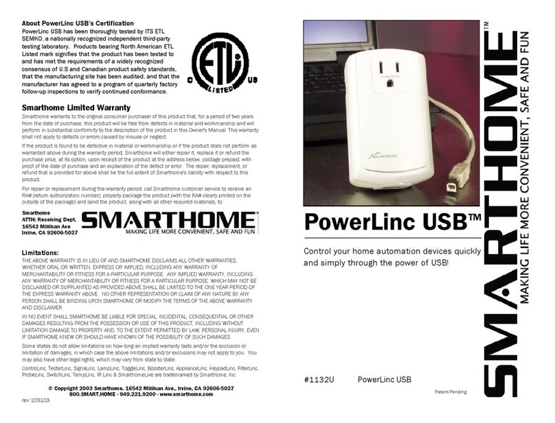
smart home 1623 IR Linc User manual

IR LincTM
Control Audio-Video equipment with X10/PLC
signals in you home!
Model #1623 IR Linc

Congratulations!
Congratulations on purchasing IR Linc, the smallest and easiest gateway for IR
automation control. The IR Linc offers the easiest way to add IR automation to your
home. For years, many home automation enthusiasts have struggled with control-
ling audio and video devices. Regular plug-in modules and even specialized univer-
sal modules can't turn on a TV or change the volume on a stereo. IR Linc will
accept regular powerline PLC/X10 signals and generate IR signals that your AV
equipment understands.
Just plug the supplied power module into a standard wall receptacle and place the
IR Linc in position, it is that simple. No tools required, no in-wall devices or wires
needed, and no hassle installation.
Key Features
• Two built-in IR blasters
• Built-in IR sensor for learning IR signals from existing remote controls
• Three jacks for attaching additional emitters (single/double or blast)
• External power sensing when used with Smarthome Probes
• Front panel status indicators
• No computer or other supporting equipment required for on-going operation
• Non-volatile memory. Contents will be retained after a power outage.
• Small sized
Other Complementary Smarthome Products
Your IR Linc is ready to be used by most any powerline-based product on the mar-
ket. However, when teamed up and used with other Smarthome automation prod-
ucts, you can transform the whole home's automation system to the same level and
sophistication normally found in multi-million dollar homes.
PC to IR LincTM
Control your whole-house audio or home theater system
from the comfort of your PC. While it is very much like
the IR Linc, it is essentially a powerful learning remote
that transmits IR signals in response to an RS-232 sig-
nal. It learns IR codes from your existing remote controls
or uses the built-in library of IR codes. All the program-
ming is stored on a Windows-based computer, so there are fewer memory con-
straints than the IR Linc.
TouchLincTM Touchscreen Controller
Smarthome's innovative TouchLinc Touchscreen controller lets
you easily control all of your PLC-controllable home systems,
including lighting, appliances, heating & air conditioning, auto-
mated drapes, and even home theater (with the help of an
intelligent controller), through a single intuitive display. Sub-
sections for controlling audio and video products are included,
or make up your own series of menus and label them how you
like!
2

Parts included with the IR Linc kit
• The IR Linc controller box
• PowerLincTM II PowerLine Adapter
• Double headed Stick-on IR Emitter
• PowerLinc II connecting cable
Please note that the PowerLinc II adapter is
designed to only work with the IR Linc controller
box. While it resembles our regular # 1132B
PowerLinc II adapter, the two are incompatible and not interchangeable. The includ-
ed PowerLinc adapter contains special circuitry and programming to support the IR
Linc control box.
Quick Start Instructions
Learning
an IR
Command
1. Press and hold the "Set" button for about one second.
The red "Active" indicator will begin to blink rapidly.
2. Press the button on the teaching remote.
Once the "Active" indicator turns off, release the button on
the remote control.
3. The green "Probe" indicator will begin to flash indicating
that the IR Linc is ready to receive PLC commands to asso-
ciate with the learned IR signal.
4. Send the PLC signal.
The green indicator will turn on solid, then off.
(See page 6 for more detailed instructions)
Overview
• The Active indicator will show that
the unit is ready to learn IR signals.
During normal use, it will blink when
IR signals are transmitted.·
• The two IR/Learn blast emitters
emit IR light to control the AV
devices. During programming, they
sense the IR light from the teaching
remote.·
• The Probe indicator is used to indi-
cate when a Smarthome probe is
detecting an ON condition. It is also
used to during learning and will blink
when PLC/X10 signals are detected
on the power line.
• The three IR Out jacks for optional
external IR emitters.
• The Probe jack will accept the
Smarthome Probes to monitor the
power status of equipment.
• The Set button is will put the IR Linc
into the learning mode, clear learned
commands, or clear the memory.
• The Powerlinc/RS232 Cable jack
connects to PowerLinc II supplied
with the IR Linc.
• The 12VDC, 300mA is not used on
the IR Linc, power for the unit is sup-
plied by the PowerLinc II adapter.
3

Optional Accessories for the IR Linc
A level of intelligence can also be added to the IR Linc by using it with one of the
Smarthome Probes. Probes may be used for many purposes including detecting the
power status of an AV device.
4
TV Detector Probe #8012 Light Detector Probe 8013
Senses the presence of the high frequency RF
emissions of a TV when it is on. Place the
white "Whip" near the rear of the set.
This sensor can be placed over the location of
an LED or any other light source to sense if
the AV device is on.
Digital Input Low Voltage
Detector Probe #8015 Video Detector Probe #8016
This probe can be attached to any device that
generates a 3-28 volt (AC or DC) signal. Some
AV equipment have low-voltage outputs that
may be used to detect the device's power sta-
tus.
Detects the presence of a baseband video sig-
nal when connected to the VIDEO OUT jack.
Can't be used with video gear that outputs a
blank or blue screen when switched off (or in
stand-by).
Contact Closure Probe #8018 Extra Emitters
This probe is ideal for detecting the condition
of a dry-contact switch. Some AV receivers
have dry-contact relays open or close when
powered on or off.
Using Mini Stick-On IR Emitters or Blast
Emitters can increase the controller’s flexibility.
The #8174 Blast Emitter will have a range of
four to seven feet when used with the IR Linc.
Blast IR
Emitter#8174 Stick-on Emitter
8171S

Installation
The IR Linc should be installed in a location that has a standard 120-volt household
receptacle readily accessible. If external Mini Stick-On IR Emitters are not being
used, place the IR Linc in a location that allows the built-in IR blasters to be within
line-of-site of the equipment. When Mini Stick-On IR Emitters are used, the IR Linc
can be placed in any location since the built-in IR blasters will not be used. Once
the location has been finalized, place the IR Linc in that location and plug in the
PowerLinc II Interface. Plug in any Mini Stick-On IR Emitters and/or probes into the
appropriate jacks. The IR Linc is now ready for use.
Installation Tips:
1 The built-in IR blaster’s light can sometimes be reflected. Therefore, direct line-
of-site may not be necessary depending on the reflecting surface or objects the
IR Linc is facing and the distance to the equipment. Experimentation with
bouncing the IR signal off of surfaces and objects may allow the IR Linc to be
placed in a location, other than direct line-of-site.
2 Any combination of Mini Stick-On IR Emitters may be used
with the built-in IR blasters. Plugging in Mini Stick-On IR
Emitters does not disconnect the built-in IR blasters. Using
this combination method allows IR Linc to control equipment
that is in direct line-of-site and A/V gear using Mini Stick-On
IR Emitters.
3 While the IR Linc can be placed in an inconspicuous location when Mini Stick-On
IR Emitters are used, the unit should be readily available for programming. The
"Active" and "Probe" indicators can be used as a visual indication of IR transmis-
sions and equipment status. The IR Linc can be programmed in one location,
and then transported to its final location without losing the stored data.
4 Be careful plugging in external emitters on the rear of the unit. If an emitter is
plugged into the Probe jack, it will be instantly destroyed!
5 When using stick on emitters, it is important that to
find the IR sensor on the equipment and place the
emitter directly over the sensor. Use a flashlight to
look into the display or bezel of the equipment to find
the sensor. Sometimes, using the original remote
control and covering the front of the equipment with
an object or thick cloth can help locate the sensor.
Try placing a computer mouse pad over the equip-
ment and working from right to left, move the mouse pad (to the left and expos-
ing the right) while shooting the remote at the equipment until a response from
the equipment to the IR signals is observed. For example, holding down the vol-
ume button on the remote control as the mouse pad is moved to the left. When
the unit begins increasing the volume, the approximate location of the IR sensor
on the equipment has been found. Next, use the same technique starting at the
top of the equipment to find the exact center of the sensor. Now that the
approximate vertical and horizontal of the sensor is known, use a flashlight to
find exactly where it is.
Place the stick on emitter over this location!
Once the IR Linc is installed, the unit can be programmed with IR commands.
However, it is recommended that a factory reset be performed before programming.
This will ensure that all the memory has been cleared of codes learned during quali-
ty testing and it will also indicate that the IR Linc is setup and operating correctly.
See page 9 for details.
Tip:
Stick-on emitters
are the most reli-
able method of
communicating to
AV gear.
5

Learning an IR Command
The IR Linc uses powerline (PLC/X10) commands for communica-
tions. A compatible transmitter will be needed before learning IR
commands. A ControLinc Duo (Smarthome #4071) or X10 Maxi-
Controller (#4020) is ideal for programming the IR Linc. Up to
seven different PLC functions can be used for each house/unit
code. The different codes are selected by the appropriate PLC
function code. The function code will determine how the IR com-
mand is transmitted. Refer to the following table for a list of the
available function codes:
#4020
Maxi-
Controller
PLC Function
Code Operation
ALL LIGHTS
ON*IR command turns ON a device. The probe will be checked
first and if the device is already on, the command will ignored.
ALL UNITS
OFF**
IR command turns OFF a device. The probe status will be
checked first and if the device is already off the IR command
will not be sent.
ON Normal IR. Only one IR command will be sent upon receipt of
the a powerline signal.
OFF Normal IR. Only one IR command will be sent upon receipt of
the powerline signal.
BRIGHT IR command is for continuous control functions like volume up
or channel up. The IR command will be sent as long as the
BRIGHT command is being received.
DIM IR command is for continuous control function such as volume
down or channel down. The IR command will be sent as long
as the DIM command is being received.
House - Unit Code
(repeated)*** Normal IR. Only one IR command will be sent upon receipt of
the powerline signal.
*To transmit the learned IR command send house/unit code and house code +"ON" from any powerline
compatible transmitter (i.e. A1, AON).
**To transmit the learned IR command send house/unit code and house code + "OFF" from any powerline
compatible transmitter (i.e. A1, AOFF)
***To transmit the learned IR command, send house/unit code once (i.e. A1).
To learn an IR command, follow these steps:
1. Disconnect any probe connected to the IR Linc.
2. Press and hold the "Set" button for about one second and release.
3. The red "Active" indicator will begin to blink rapidly; the IR Linc is now ready to
learn an IR signal.
4. Point the remote control at the two built-in IR blasters on the front of IR Linc.
5. Press the button on the remote control that is to be learned. Once the red
indicator turns off, release the button on the remote control. The IR signal has
been successfully learned into the IR Linc.
6

6. The green "Probe" indicator will begin to flash indicating that the IR Linc is
ready to receive PLC commands to associate with the learned IR signal.
7. From a compatible transmitter, send the house/unit code that is to be identi-
fied with this IR signal followed by the function code (ON, OFF, Dim, etc.).
8. The green indicator will turn on solid for a few seconds to indicate that it suc-
cessfully received the PLC commands then turn off.
Learning Tips:
• The remote should be level with the
IR Linc and directly in front on it.
The emitter on the front of the
remote should be located directly
between the two built-in IR blasters
on the front of the IR Linc and locat-
ed about 1 to 2 inches from them.
• The remote should have fresh strong batteries. If commands are not being
learned correctly or it takes multiple tries, try changing the batteries.
• Since the green "Probe" indicator is used to indicate status during learning
cycles, the probe be disconnected during learning.
• The IR learning time is fixed at no more than five seconds. IR Linc will allow 15
seconds for the capturing the associated powerline signal.
• Sunlight, florescent light sources and plasma screen monitors can interfere with
IR reception. The best learning will occur in darkened rooms.
• The length of time the teaching remote's button is held down can have an effect
on learning success. In some cases, the button may need to be held down
longer than normal for the IR Linc to successfully sample the signal. Other
times, it may only need to be held down less than a second.
Errors that can occur during learning
If powerline commands are sent while the green "Probe"
indicator is blinking and the green indicator turns off
instead of going solid, the IR command was not learned
properly. The command was not saved to memory and
no deleting is necessary. Re-teach the IR command by
following the instructions above. Sending a powerline
command during the IR learning cycle will take the IR
Link out of the learning mode.
The IR Linc has a finite amount of memory for learning IR commands. The total
number of commands it can learn is based upon the length of each IR command. A
maximum of 31 IR commands can be learned, assuming that the sum of each com-
mand does not exceed the IR Linc Controller's memory. If the green "Probe" indica-
tor goes solid and then turns off instead of blinking after the command is learned,
the memory is full.
7
Tip:
Unplug or disable other
PLC/ X10 transmitters in
the house during program-
ming. This will reduce the
likelihood of an uninten-
tional signal being learned
by the IR Linc.

Deleting Individual IR Commands
A learned IR commands can be deleted at any time. To delete an IR command, fol-
low these steps:
1. Press and hold the "Set" on the back of the IR Linc for one second
2. The red "Active" indicator will begin to blink rapidly
3. Send the PLC house/unit code and function code for that IR command
4. The green "Probe" indicator will turn on for a few seconds then turn off
5. Once the "Active" indicator stops blinking, the IR command has been deleted
Macros
IR Linc comes with a powerful macro feature that allows more than one IR command
to be learned under a single powerline command. This allows the user to transmit
multiple IR commands with only a single command. When a single command is
received, the IR Linc will transmit IR signals in the order that they are learned.
For example, when A1 AON is received, all the IR commands used to turn on the TV
and VCR then play a movie can be learned. To do this, learn the commands in the
following order:
TV Power (Turns on the power to the TV)
VCR Power (Turns on the power to the VCR)
TV Channel 3 (Changes the TV to channel 3)
VCR Play (Starts the VCR playing back the tape)
Each time an A1 AON signal is received, IR Linc will transmit all of these commands,
in the order they were learned.
To teach the IR Linc a series of IR commands to be used in a macro, each command
will be learned individually. That is, each IR command will go through steps 1
through 8 on page 6. The only difference is that in step 7, the PLC command sent is
the same for all the IR commands.
Multiple IR signals can also be learned to the PLC commands that check probe sta-
tus. The IR Linc will send out the multiple IR commands as it would under a normal
command except that its checks the probe status before it sends out each IR com-
mand. If the probe status changes while it is going through the macro list it will stop
at that point in the macro list and not transmit the remaining IR commands.
Other Features
Powerline Activity
If a probe is not being used or it is attached, but not detecting that the AV device is
powered on, the green "Probe" indicator is used to indicate activity on the powerline.
When IR Linc sees a valid command on the powerline, whether it is for the IR Linc or
not, the green "Probe" indicator will flash. This can be used for troubleshooting or to
ensure the IR Linc is plugged into a receptacle with good signal strength.
Probe Status
IR Linc will transmit powerline commands based on the probe’s status. When a
probe goes from an "OFF" condition to an "ON" state, IR Linc will transmit the
house/unit code associated with the learned IR command that checks the probe sta-
tus plus the house code + "ON". For example, if an IR command were learned under
A1, A ALL LIGHTS ON, (the function code indicates that it will check the status of the
probe), IR Linc will transmit A1, AON when the probe went to the "ON" state. If the
probe goes from "ON" to "OFF", IR Linc will send A1, AOFF. If there is more than one
house/unit code associated with checking the probe’s status, IR Linc will send out
the house/unit code that was last learned.
8

Factory Reset (to default settings)
If the IR Linc begins to operate strangely, the factory-reset procedure can be used to
clear the IR Linc Controller's memory and restore its factory default settings. It is
also recommended that a factory reset of the IR Linc be performed before program-
ming. This will ensure that all the memory has been cleared of codes learned dur-
ing quality testing and it will also indicate that the IR
Linc is setup and operating correctly. A factory reset
of the IR Linc can be performed at any time.
This procedure will clear the unit of all addresses
and IR signals learned.
1. Press and hold the SET button for five seconds
until the green "Probe" indicator comes on.
2. The green indicator will remain lit for a few sec-
onds then it will turn off.
3. When the indicator turns off, the master reset
Tip:
A reset should only be done if
the learning processed is going
to restarted. There is no way of
retrieving IR commands or
undoing a factory reset.
Individual IR commands can be
deleted; see Deleting
Individual
IR
Commands.
PLC
Address
Function Code
(ON/OFF, Bright/Dim,
All Lights ON
All Units OFF)
Device
being
Controlled IR Signals Sent
(in order they were programmed)
F5 All Lights on
(using Video Probe) Sat. Receiver Power on
F5 ON Television Power on
F5 ON Television Video 2 Input
9
Troubleshooting & Technical Support

Problem Possible Cause & Solution
The IR Linc appears to
be locked up.
Remove and reset the power.
Disconnect all the emitters and the probe, and unplug the unit for three min-
utes, then reconnect.
If it is still locked up, perform a factory reset.
How can I get the power ON
command to only be issued
if the AV device is off?
Some AV devices have discrete IR signals for power on and off. If the remote
control has these buttons, use them. Otherwise, use a Smarthome Probe.
The IR command will be taught to the IR Linc with any address and the All
Light ON command. See Probe Status on page 8
I am having problems learn-
ing one of my remote con-
trols into the IR Linc.
There could be several factors causing this problem.
Check the tips on page 7.
The remote's IR frequency may be beyond the normal 40kHz. Excessive IR
light or brightly lit room could cause problems. Teaching IR Linc in a dark room
produces the best results.
When an powerline com-
mand is sent, the
Probe LED does not blink.
The PowerLinc II adapter is not "seeing" the powerline signal.
Make sure the adapter is not plugged into a power strip that filters the electric-
ity. The equipment electrically near the adapter may be sucking up PLC sig-
nals or you may need a phase coupler for the powerline signals. Visit
http://www.smarthome.com/project_x10.html to learn more.
How can I speed up the
to IR system?
The IR Linc will send IR signals when the first address is received. If a home
automation interface is being used, try sending only the address, which is
sometimes known as a "Keypress" command. The only exception to this is
when an IR command is learned as "Continuous" in which case the Bright and
Dim commands are used to trigger an IR output.
Can the IR Linc be used
on 230-volt systems like
those found outside of
North America?
It can't be used on 230-volt electrical systems, even with a step-down trans-
former. A voltage-converting transformer will block powerline signals. The
PowerLinc II adapter (which contains special circuitry the IR Linc box needs) is
not substitutable with other powerline interfaces.
Sometimes the signals
from the built-in blaster
don't trigger the AV device.
Using the blast emitters on the front of the IR Linc is the least reliable method
of controlling AV devices. We don't recommend bouncing IR signals off walls,
doors, or other surroundings. Additionally, external IR light interference from
sunlight, fluorescent lights, and plasma screen monitors may hamper reliable
operation. By using Mini Stick-on emitters, most IR light reliability problems
can be overcome.
How can I get around the
31 IR command limit.
The memory of the IR Linc can't be increased and the commands can't be
compressed. By investing in a second IR Linc, the work can be divided and in
most cases, two IR Linc Controllers controlling a complex home theater system
will cut down on total set up time after a command has been issued.
How do I get an IR com-
mand to repeat, like
for volume up/down?
When teaching the IR commands to the IR Linc, after sending the address for
the command (F4, P12, etc.), press the BRIGHT or DIM button on the con-
troller. You will need to use a 4020 Maxi-Controller for this or a controller that
can send addresses and commands separately. See page 6 for more informa-
tion.
I can't see my Mini Stick-on
Emitters blink when a com-
mand is sent.
Most brands of Mini Stick-on Emitters don't produce visible light we humans
can see.
I plugged the emitter into
the "Probe" jack accidental-
ly, now it does
not work.
The emitter was most likely destroyed. The "Probe" jack's voltage is a little too
much for the emitter to handle. Sorry about this, but we warned you about this
back on the installation section (step 4) on page 5.
10

Still having trouble....
If these solutions have been tried, the manual has been reviewed and you still can-
not resolve an issue you’re having with the IR Linc;
• Search our on-line knowledge base at: http://smarthome.custhelp.com
• Call our Technical Support Dept. at 949-221-9200
Invest in better Home
Automation Products
Unlike most electric items, many PLC-
based products haven't changed much
over the years.
Our Marketing and Customer Service teams surveyed our cus-
tomers, like you, and our engineers have invented new and bet-
ter wall switches and plug-in modules. We include more fea-
tures, higher load handling, and better signal sensitivity for a
superior user experience. While in some cases, they cost
more; we hope
you'll agree that not having to replace a dead module every
couple years is worth the added expense and reduced aggrava-
tion. Please visit a retailer or distributor for the complete line
of automation products from Smarthome Design.
KeypadLinc 6 with
450W integrated
dimmer
Specifications
• Number of IR Commands: 31
• Memory Volatility: EEPROM non-volatile memory
• Input Power: 12 Volts DC (supplied by PowerLinc Interface)
• Dimensions: 4.0in. wide, 2.5in. deep, 1.1in. high
• Weight: .2 pounds
• Emitters: 2 built-in “blast” and up to three external emitters
Other Smarthome Products
Your controller is compatible with many
of our other home automation products.
If you need a traditional-looking wall
switch, check out the new ToggleLinc
series of wall switches or the new
SwitchLinc RX, which is ideal for retro-
fit applications where there isn't a neu-
tral wire at the switch's wall box. The KeypadLinc Wall Mounted Transmitter allows
you to control multiple devices from one location at the press of a single button.
And for plug-in devices, the ApplianceLinc and LampLinc modules will automate
just about anything that plugs in. Please visit the Smarthome web site or contact
your distributor for more information. 11

About PowerLinc II’s Certification
The PowerLinc Interface has been thoroughly tested by ITS ETL SEMKO,
a nationally recognized independent third-party testing laboratory.
Products bearing North American ETL Listed mark signifies that the
product has been tested to and has met the requirements of a widely
recognized consensus of U.S. and Canadian product safety standards,
that the manufacturing site has been audited, and that the manufactur-
er has agreed to a program of quarterly factory follow-up inspections to
verify continued conformance.
Smarthome Limited Warranty
Smarthome warrants to the original consumer purchaser of this product that, for a period of two years
from the date of purchase, this product will be free from defects in material and workmanship and will
perform in substantial conformity to the description of the product in this Owner's Manual. This warranty
shall not apply to defects or errors caused by misuse or neglect.
If the product is found to be defective in material or workmanship or if the product does not perform as
warranted above during the warranty period, Smarthome will either repair it, replace it or refund the pur-
chase price, at its option, upon receipt of the product at the address below, postage prepaid, with proof
of the date of purchase and an explanation of the defect or error. The repair, replacement, or refund
that is provided for above shall be the full extent of Smarthome's liability with respect to this product.
For repair or replacement during the warranty period, call Smarthome customer service to receive an
RA# (return authorization number), properly package the product (with the RA# clearly printed on the
outside of the package) and send the product, along with all other required materials, to:
Smarthome
ATTN: Receiving Dept.
16542 Millikan Ave
Irvine, CA 92606-5027
Limitations:
THE ABOVE WARRANTY IS IN LIEU OF AND SMARTHOME DISCLAIMS ALL OTHER WARRANTIES,
WHETHER ORAL OR WRITTEN, EXPRESS OR IMPLIED, INCLUDING ANY WARRANTY OF MERCHANTABILI-
TY OR FITNESS FOR A PARTICULAR PURPOSE. ANY IMPLIED WARRANTY, INCLUDING ANY WARRANTY
OF MERCHANTABILITY OR FITNESS FOR A PARTICULAR PURPOSE, WHICH MAY NOT BE DISCLAIMED OR
SUPPLANTED AS PROVIDED ABOVE SHALL BE LIMITED TO THE ONE YEAR PERIOD OF THE EXPRESS
WARRANTY ABOVE. NO OTHER REPRESENTATION OR CLAIM OF ANY NATURE BY ANY PERSON SHALL
BE BINDING UPON SMARTHOME OR MODIFY THE TERMS OF THE ABOVE WARRANTY AND DISCLAIMER.
IN NO EVENT SHALL SMARTHOME BE LIABLE FOR SPECIAL, INCIDENTAL, CONSEQUENTIAL OR OTHER
DAMAGES RESULTING FROM THE POSSESSION OR USE OF THIS PRODUCT, INCLUDING WITHOUT LIMI-
TATION DAMAGE TO PROPERTY AND, TO THE EXTENT PERMITTED BY LAW, PERSONAL INJURY, EVEN IF
SMARTHOME KNEW OR SHOULD HAVE KNOWN OF THE POSSIBILITY OF SUCH DAMAGES.
Some states do not allow limitations on how long an implied warranty lasts and/or the exclusion or limi-
tation of damages, in which case the above limitations and/or exclusions may not apply to you. You may
also have other legal rights, which may vary from state to state.
ControLinc, TesterLinc, SignaLinc, LampLinc, ToggleLinc, BoosterLinc, ApplianceLinc, KeypadLinc, FilterLinc,
ProbeLinc, SwitchLinc, TempLinc, IR Linc & SmarthomeLive are trademarked by Smarthome, Inc.
© Copyright 2004 Smarthome, 16542 Millikan Ave., Irvine, CA 92606-5027
800.SMART.HOME - 949.221.9200- www.smarthome.com
rev 013004
Table of contents
Other smart home Control Unit manuals
Popular Control Unit manuals by other brands
Honeywell
Honeywell Silent Knight SK-Monitor Installation and maintenance instructions
Redline Communications
Redline Communications RDL-3000 Series product manual

Flowserve
Flowserve R6 Installation, operation and maintenance instructions
Festo
Festo VABF-S4-1-V2B1 series operating instructions

Samson
Samson 41-23 Series Mounting and operating instructions

Elektrogas
Elektrogas VMM quick start guide
FAAC
FAAC 844T instructions

DAV TECH
DAV TECH DAS 50N Installation and maintenance guide
YASKAWA
YASKAWA S-II Series instructions

Emerson
Emerson Fisher TBX instruction manual
National Instruments
National Instruments NI 9871 Operating instructions and specifications
Waveshare
Waveshare RS485 TO ETH user manual
