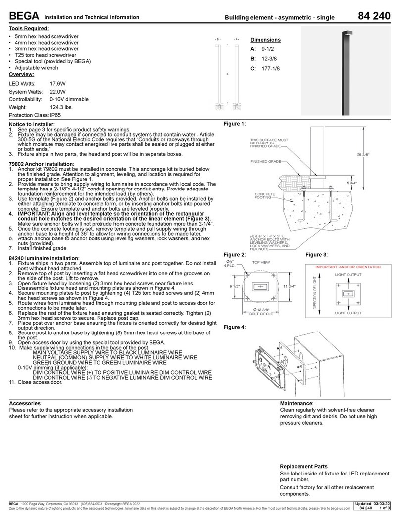
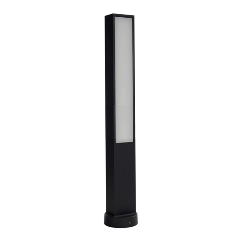
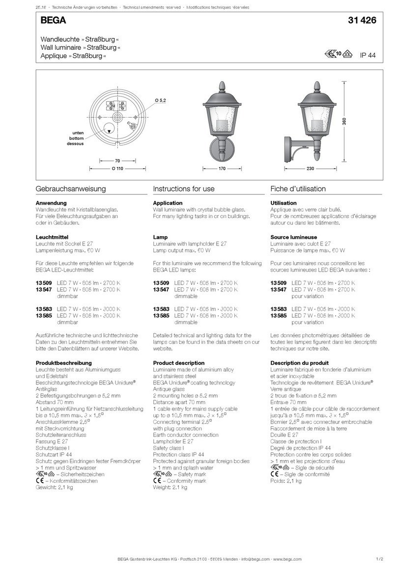
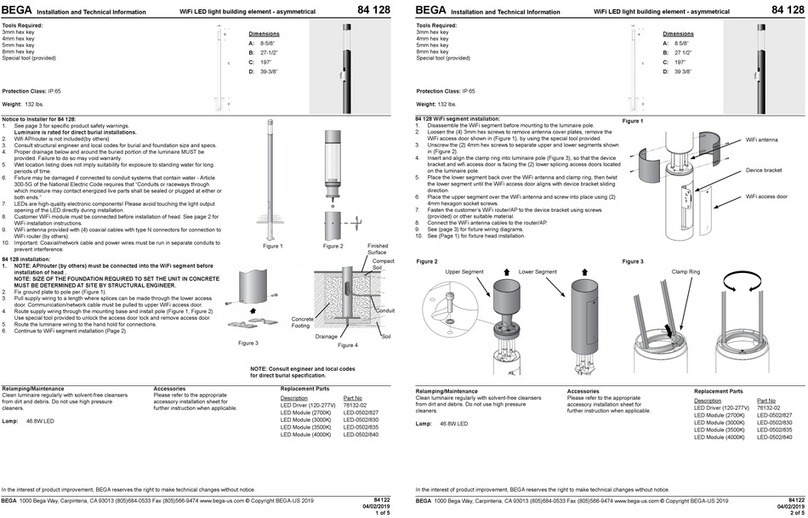
manuals.online logo
Brands
  1. Home
  2. •
  3. Brands
  4. •
  5. BEGA
  6. •
  7. Outdoor Light
  8. •
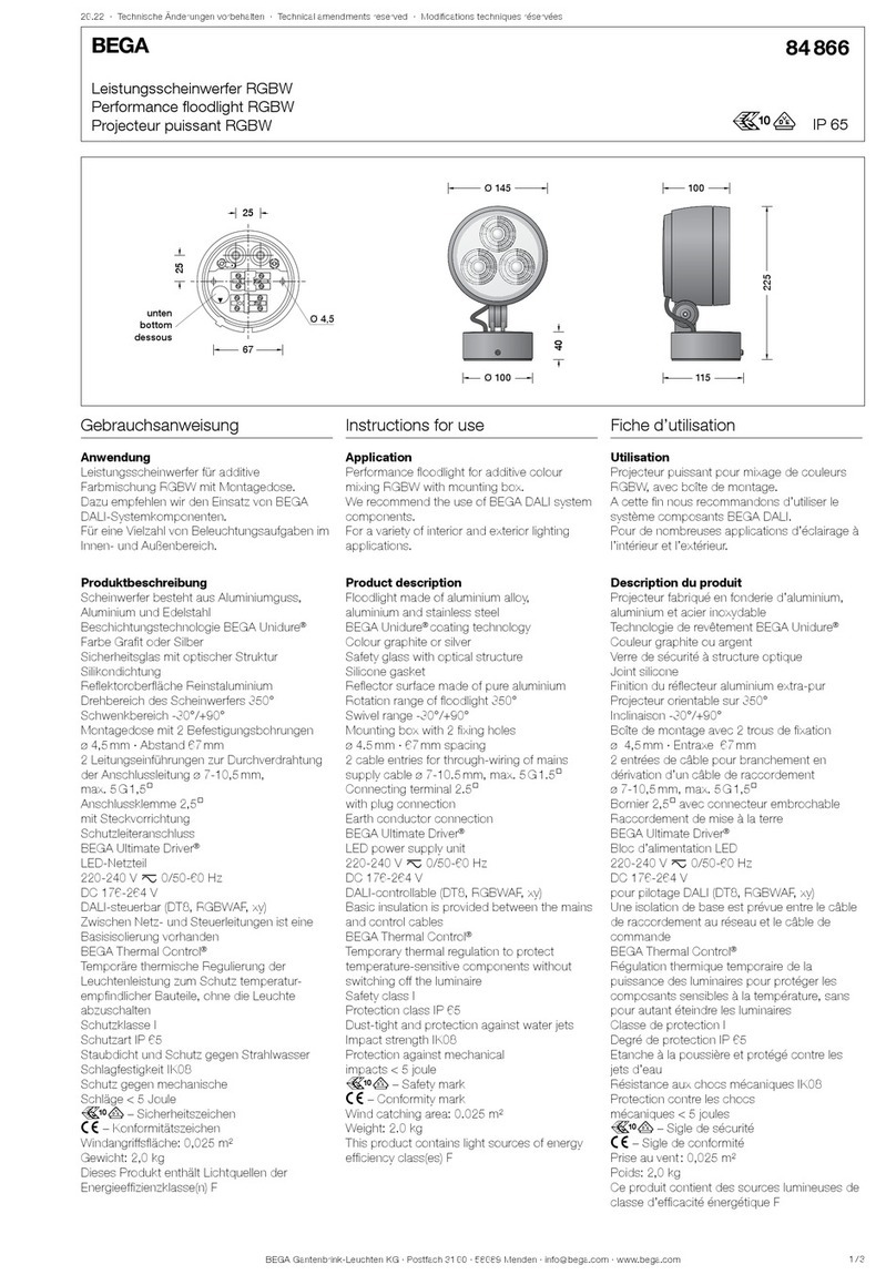
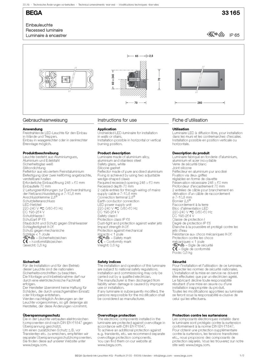
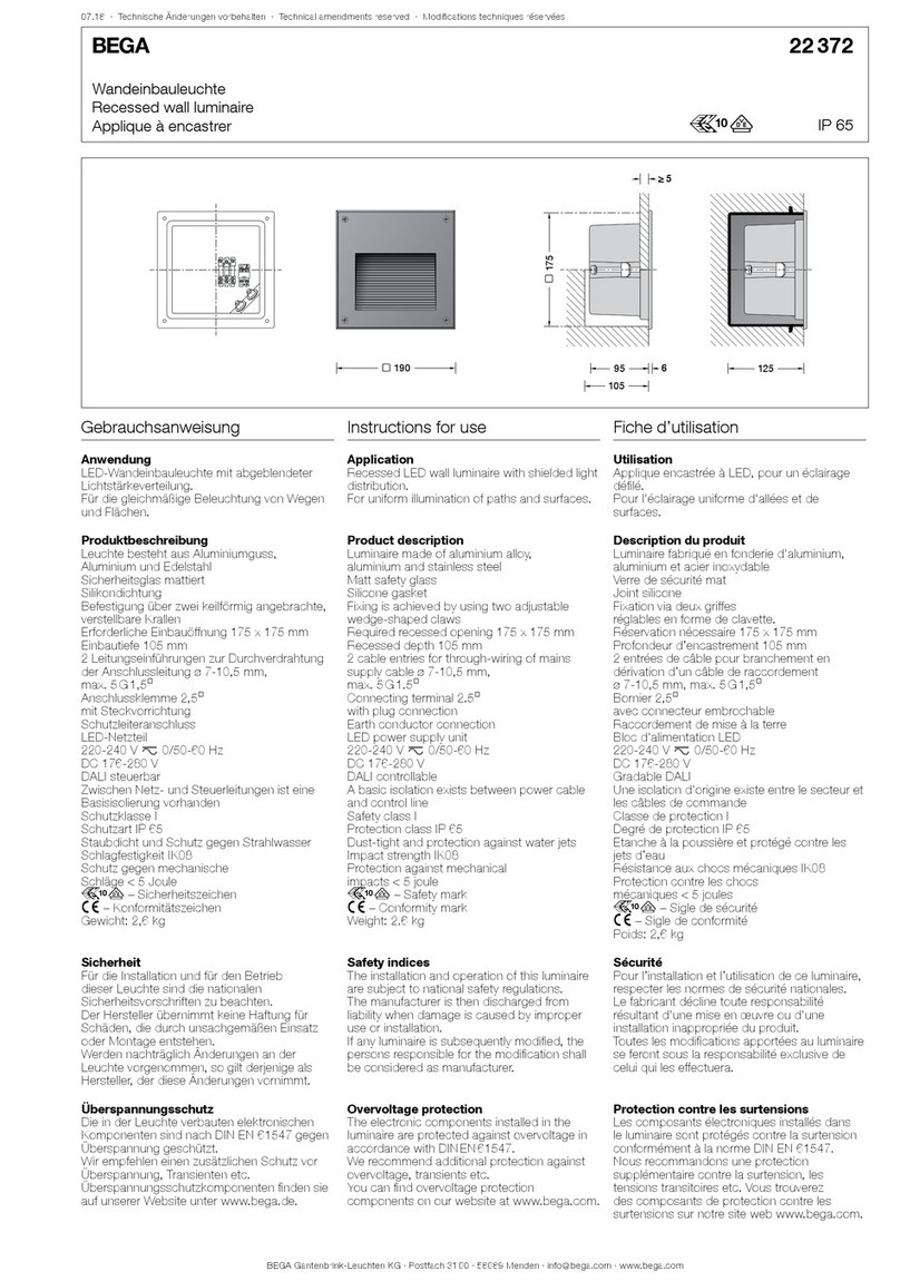
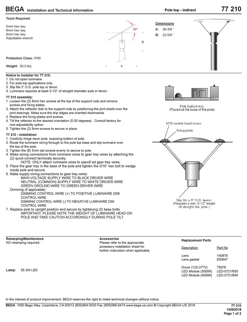
  9. BEGA 84 715 User manual

BEGA 84 715 User manual

BEGA Gantenbrink-Leuchten KG · Postfach 31 60 · 58689 Menden · info@bega.com · www.bega.com 1/4
18.21 · Technische Änderungen vorbehalten · Technical amendments reserved · Modications techniques réservées
IP 65
!
Lichtbauelementrohr
Light building element tube
Tube de prolé lumineux
84 715
r
39003900
610610
8×8
300
×
85
300
×
85
Ø 170Ø 170
□ 200
□ 200
Ø 340
Ø 20
22
Gebrauchsanweisung Instructions for use Fiche d’utilisation
Anwendung
Lichtbauelementrohr 170mm aus Aluminium
mit Fußplatte.
Mit einstellbarem Scheinwerfer für die
Anstrahlung architektonischer Details im
unmittelbaren Umfeld des Lichtbauelements.
Das Lichtbauelementrohr wird mit seiner
Fußplatte direkt auf ein Fundament oder
Erdstück geschraubt.
Für die Verwendung in Kombination mit einem
Lichtbauelementkopf.
Application
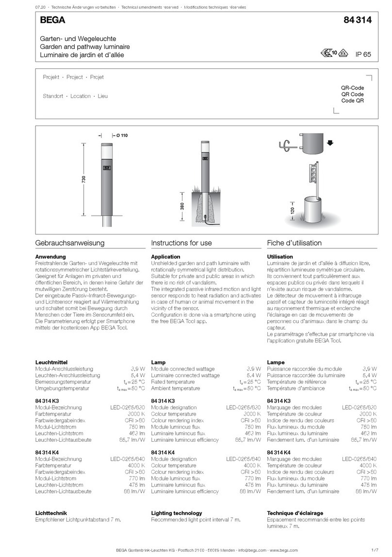
Aluminium light building element tube
ø170 mm with base plate.
With adjustable oodlight for the illumination of
architectural details in the immediate vicinity of
the light building element.
The light building element tube is bolted directly
onto a foundation or anchorage unit via its base
plate.
For use in combination with a light building
element head.
Application
Tube de prolé lumineux ø170 mm en
aluminium avec platine.
Avec projecteur réglable pour l’illumination
de détails architecturaux situés à proximité
immédiate du prolé lumineux.
Le tube de prolé lumineux se visse
directement avec sa platine sur un massif de
fondation ou une pièce à enterrer.
Pour une utilisation en association avec une
tête de prolé lumineux.
Produktbeschreibung
Lichtbauelementrohr aus Aluminium,
pulverbeschichtet und lackiert
Beschichtungstechnologie BEGA Unidure®
Fußplatte mit 4 Befestigungsbohrungen
zur Montage auf ein Fundament oder
Erdstück (Ergänzungsteil 70 899)
Einstellbares Scheinwerfermodul aus
Aluminiumguss, Aluminium und Edelstahl
Sicherheitsglas klar
Reektoroberäche Reinstaluminium
Optische Silikonlinse · BEGA Hybrid Optics®
Neigungswinkel des einzelnen Scheinwerfers ist
von 0° bis 30° einstellbar, um 360° drehbar
Scheinwerfersegment kann 360° um die
senkrechte Achse des Lichtbauelements
gedreht werden
Mit eingesetzter Tür aus Aluminiumdruckguss
Vierkant-Türverschluss (SW8)
Anschlusskasten 71 084
zur Durchverdrahtung für 2 Kabel bis 7×6@
Klemmenbelegung L1· L2 · L3 · N · PE
2 Anschlussklemmen zum Anschluss
von DALI Steuerleitungen
Sicherungsklemme mit Feinsicherung
6,3A träge ø 5 ×20 mm
r– Sicherheitszeichen
c – Konformitätszeichen
Windangriffsäche:0,66m²
Gewicht: 30,0 kg
Dieses Produkt enthält Lichtquellen der
Energieefzienzklassen C, D
Product description
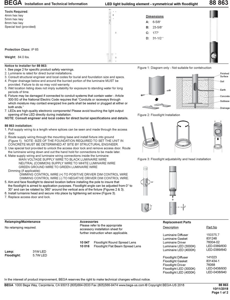
Aluminium light building element tube,
powder-coated and painted
BEGA Unidure® coating technology
Base plate with 4 xing holes
for installation on a foundation or
anchorage unit (accessory 70 899)
Adjustable oodlight module made of
aluminium alloy, aluminium and stainless steel
Clear safety glass
Reector surface made of pure aluminium
Optical silicone lens · BEGA Hybrid Optics®
Inclination angle of the individual oodlight is
adjustable from 0° to 30°, adjustable 360°
Floodlight segment can be rotated by 360°
around the vertical axis of the light building
element
With inserted door made of die cast aluminium
Square door latch (wrench size8 mm)
Connection box 71 084
for through-wiring for 2 cables up to 7×6@
Terminal connection L1· L2 · L3 · N · PE
2 connecting terminals for connecting DALI
control cables
Fuse terminal with micro fuse
6,3A slow ø 5 ×20 mm
r– Safety mark
c – Conformity mark
Wind catching area:0.66m²
Weight: 30.0 kg
This product contains light sources of energy
efciency classes C, D
Description du produit
Tube de prolé lumineux en aluminium,
poudré et laqué
Technologie de revêtement BEGA Unidure®
Platine avec 4 trous de xation pour
l’installation sur un massif de fondation ou
sur la pièce enterrée (Accessoire 70 899)
Module de projecteur fabriqué en fonderie
d’aluminium, aluminium et acier inoxydable
Verre de sécurité clair
Finition du réecteur aluminium extra-pur
Lentille optique en silicone
BEGA Hybrid Optics®
L’angle d’inclinaison de chaque projecteur est
réglable de 0° à 30°, orientable sur 360°
Chacun de projecteur peut pivoter à 360°
autour de l’axe vertical du prolé lumineux
Avec porte fabriquée en fonderie d'aluminium
injecté
Fermeture à vis à quatre pans (SW8)
Boîte de connexion 71 084 pour branchement
en dérivation pour 2 câbles max. 7×6@
Disposition de bornes L1· L2 · L3 · N · PE
2 bornes pour le raccordement de câbles de
commande DALI
Porte fusible avec fusible à l n
6,3A lent ø 5 ×20 mm
r– Sigle de sécurité
c – Sigle de conformité
Prise au vent :0,66m²
Poids: 30,0 kg
Ce produit contient des sources lumineuses de
classe d’efcacité énergétique C, D
BEGA Gantenbrink-Leuchten KG · Postfach 31 60 · 58689 Menden · info@bega.com · www.bega.com
2/4
Produkteigenschaften
Widerstand gegen horizontale Lasten:
vref,0 = 32 m/s
Geländekategorie: 1
nach DIN EN 1991-1-4
Leuchten mit einem Gewicht bis 40kg
und einer Windangriffsäche max. 0,28m²
Verformungsklasse: 1 – Sicherheitsklasse: A
in Anlehnung an DIN EN 40-3-3
Verhalten bei Fahrzeuganprall nach
DIN EN 12767 (passive Sicherheit): Klasse 0
Product characteristics
Resistance against horizontal loads
vref,0 = 32 m/s
Terrain category: 1
in accordance with DIN EN 1991-1-4
Luminaires with a maximum weight of 40kg
for a wind catching area max. 0.28m²
Deformation class: 1 – Safety class: A
based on DIN EN 40-3-3
Properties in case of vehicle impact
(passive safety): class 0 in accordance with
DIN EN 12767
Caractéristiques de produits
Résistance aux charges horizontales:
vref,0 = 32 m/s
Catégorie de terrain: 1
selon DIN EN 1991-1-4
Luminaires avec un poids jusqu'à: 40kg
et une surface de prise au vent: 0,28m²
Classe de déformation 1 –
Classe de sécurité A selon DIN EN 40-3-3
Performance en cas d’impact d’un véhicule
(sécurité passive): Classe 0
Sicherheit
Für die Installation und für den Betrieb dieses
Lichtbauelementrohres sind die nationalen
Sicherheitsvorschriften zu beachten.
Der Hersteller übernimmt keine Haftung für
Schäden, die durch unsachgemäßen Einsatz
oder Montage entstehen.
Werden nachträglich Änderungen an dem
Lichtbauelementrohr vorgenommen, so gilt
derjenige als Hersteller, der diese Änderungen
vornimmt.
Safety
National safety regulations must be observed
when installing and operating this light building
element tube.
The manufacturer accepts no liability for
damage caused by improper use or installation.
If subsequent modications are made to the
light building element tube, the party who
makes these modications is deemed to be the
manufacturer.
Sécurité
Pour l’installation et l’utilisation de ce tube
de prolé lumineux, respecter les normes de
sécurité nationales.
Le fabricant décline toute responsabilité pour
les dommages résultant d’une utilisation ou
d’une installation inappropriée du produit.
Si des modications sont ultérieurement
apportées à ce tube de prolé lumineux,
l’intervenant qui les aura effectuées est alors
considéré comme le fabricant.
Erdreich · Soil · Terre
Sauberkeitsschicht · Sub-base
Couche d’assainissement
Drainage · Drainage · Drainage
BEGA 70 899
Beton · Concrete · Béton
verdichteter Boden
Compacted soil · Sol damé
900 × 900900 × 900900 × 900900 × 900
800800
700700
700700
Montage
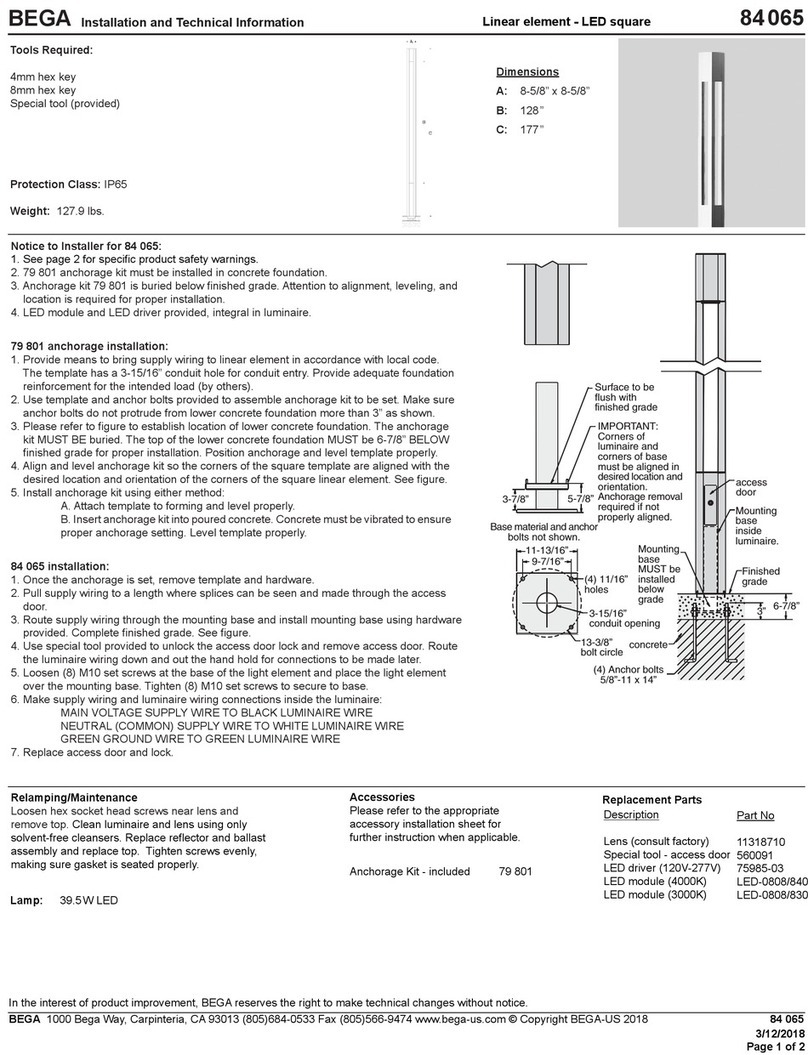
Das Lichtbauelementrohr ist je nach Einsatzart,
Leuchtengröße und Gewicht standsicher zu
gründen.
Die Fundamentgrösse ist abhängig von der
Topographie, Bodenbeschaffenheit und
Windbelastung und muss jeweils bauseits
bestimmt werden.
Dazu gilt die Norm DIN1045.
Die obige beispielhafte Fundamentempfehlung
gilt für einen tragfähigen Baugrund.
Bei Montage auf einem Fundament bitte
beachten: Feuchter Beton kann stark alkalisch
sein und darf nicht dauerhaft mit der Leuchte in
Kontakt kommen.
Wir empfehlen, den Montagebereich zu
drainieren und mit Isolieranstrich zu versehen.
Für den elektrischen Anschluss ist eine
Kabellänge von ca. 1m über Oberkante
Bodenbelag vorzusehen.
Verschluss der Montagetür entriegeln und
Montagetür entnehmen.
Erdkabel in das Lichtbauelementrohr führen.
Lichtbauelementrohr auf Fundament oder
Erdstück (Ergänzungsteil 70 899) standsicher
befestigen.
Das Befestigungsmaterial für die Montage auf
ein Fundament ist bauseits festzulegen und
zu stellen: z. B. Steinschrauben aus Edelstahl
M16x300DIN529.
Dabei auf bauaufsichtliche Zulassung achten.
Installation
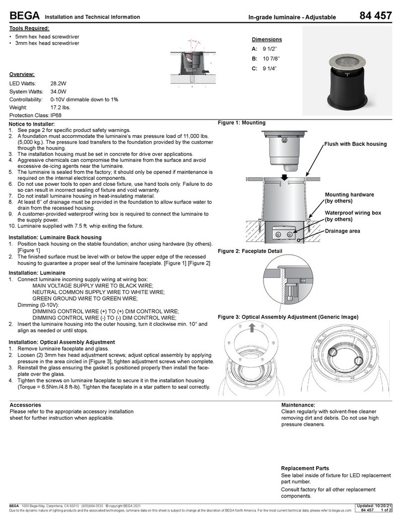
The light building element tube requires a stable
foundation appropriate to its intended use and
the size and weight of the luminaire.
The size of the foundation depends on the
topography, soil composition and wind load,
and must be determined by the customer.
DIN1045 applies.
The sample foundation recommendation above
applies to a load-bearing substrate.
In case of installation on a foundation, please
observe the following: Wet concrete can be
highly alkaline and must not come into contact
with the luminaire permanently.
We recommend draining the installation area
and painting it with insulating paint.
For the electrical connection a cable length of
approx. 1 m above mounting surface must be
provided.
Unlock the fastener of the installation door and
remove the installation door.
Thread the underground cable into the light
building element tube.
Securely anchor the light building element tube
in the foundation or anchorage unit (accessory
part 70 899).
The xing material for installing on a foundation
is to be determined and provided by the
customer: e.g. stainless steel stone bolts
M16x300DIN529.
Building inspection approval must be obtained.
Installation
Le tube de prolé lumineux doit être implanté
de manière stable en fonction du type
d’utilisation, de la taille du luminaire et de son
poids.
Les dimensions du massif de fondation
dépendent de la topographie, de la constitution
du sol et de la charge du vent, et doivent être
déterminées par le client.
La norme DIN1045 est alors applicable.
Les massifs de fondation recommandés ci-
dessus à titre d’exemple sont valables pour un
sol porteur résistant.
Attention : En cas d’installation sur un massif
de fondation: La laitance du béton peut être
fortement alcaline et ne doit pas être en
contact durable avec le luminaire. La surface
où le luminaire est installé doit être draînée et
protégée par une matière isolante.
Pour le raccordement électrique une longueur
de câble de 1 m au-dessus du bord supérieur
de la couche de nition doit être prévue.
Déverrouiller le dispositif de fermeture et retirer
la porte de montage.
Introduire le câble souterrain dans le tube du
prolé lumineux.
Fixer le tube du prolé lumineux et le stabiliser
sur le massif de fondation ou la pièce à enterrer
(pièce complémentaire 70 899).
Le matériel de xation pour l’installation sur un
massif de fondation doit être déni et fourni
par le client: par ex., vis à pierre en acier
inoxydable M16x300DIN529.
Veiller ce faisant à rester conforme à
l’homologation technique de la construction.
BEGA Gantenbrink-Leuchten KG · Postfach 31 60 · 58689 Menden · info@bega.com · www.bega.com 3/4
Montage Scheinwerfersegment:
Innensechskantschrauben(unlackiert - SW 6)
im Scheinwerfersegment lösen und Spannring
herausnehmen.
Spannring – wie in der Skizze dargestellt – in
die obere Öffnung am Lichtbauelementrohr
einsetzen und ausrichten.
Der Pfeil auf dem Spannring kennzeichnet die
spätere Position des Scheinwerfers.
Verbindungsleitung in das Lichtbauelementrohr
einführen und Scheinwerfersegment mit
Spannring verschrauben.
Innensechskantschrauben gleichmäßig fest
anziehen.
Anzugsdrehmoment=12Nm.
Einstellung der Ausstrahlrichtung:
Beide Innensechskantschrauben
am Scheinwerfer etwas lösen und
Transportsicherung entfernen.
Neigungswinkel und Ausstrahlrichtung der LED
einstellen.
Innensechskantschrauben gleichmäßig fest
anziehen.
Installation of the oodlight segment:
Loosen the hexagon socket screws(without
nish coating - wrench size6) in the oodlight
segment and remove the clamping ring.
Insert the clamping ring – as shown in the
drawing – into the upper opening of the light
building element tube and align accordingly.
The arrow on the clamping ring indicates the
eventual position of the oodlight.
Thread the connection cable into the light
building element tube and screw the oodlight
segment onto the clamping ring.
Tighten the hexagon socket screws evenly.
Torque = 12 Nm.
Setting the beam direction:
Slightly loosen the two hexagon socket screws
on the oodlight and remove the transport lock.
Set the inclination angle and beam direction of
the LED.
Tighten the hexagon socket screws evenly.
Installation du segment de projecteur:
Desserrer les vis à six pans creux(non laqué -
SW 6) dans le segment du projecteur et retirer
la bague de serrage.
Positionner la bague de serrage (comme
indiqué sur le schéma) dans l’ouverture
supérieure du tube du prolé lumineux et
l’orienter.
La èche qui gure sur la bague de serrage
indique la position ultérieure du projecteur.
Introduire le câble de raccordement dans le
tube du prolé lumineux et visser le segment de
projecteur avec la bague de serrage.
Serrer fort et uniformément les vis à sixpans
creux.
Couple de serrage=12Nm.
Réglage de l’orientation du faisceau:
Desserrer légèrement les deux vis à six pans
creux du projecteur et retirer la sécurité de
transport.
Ajuster l’angle d’inclinaison et l’orientation du
faisceau de la LED.
Serrer fort et uniformément les vis à sixpans
creux.
Montage Lichtbauelementkopf:
Montage und elektrischen Anschluss des
ausgewählten Lichtbauelementkopfes
vornehmen.
Bitte hierzu die entsprechende
Gebrauchsanweisung beachten.
Anschlusskasten öffnen.
Erdkabel, Scheinwerfer- und Leuchten-
anschlussleitung durch die Leitungseinführung
in den Anschlusskasten führen.
Schutzleiterverbindung herstellen und
elektrischen Anschluss vornehmen.
Auf richtige Belegung der Anschluss-
leitung achten. Den Netzanschluss an der
braunen (L), blauen (N) und grün-gelben Ader
(1) vornehmen.
Der Anschluss der Steuerleitungen erfolgt
über die beiden mit DALI gekennzeichneten
Adern. Bei Nichtbelegung dieser Adern werden
Leuchtenkopf und Scheinwerfer mit voller
Lichtleistung betrieben.
Anschlusskasten schließen.
Tür einsetzen und verriegeln.
Installation of the light building element
head:
Install and establish the electrical connection
for the selected light building element head.
Please refer to the corresponding instructions
for use.
Open the connection box.
Lead the mains supply cable, oodlight and
luminaire connection cable through the cable
entry into the connection box.
Make the earth conductor connection and the
electrical connection.
Note correct conguration of the mains supply
cable. The phase is connected to the brown
wire (L), the neutral conductor to the blue wire
(N) and earth conductor at the (1) marked
wire.
The connection of the control cables is
achieved by means of the both leads marked
with DALI. In case these leads are not used the
luminaire head and oodlight will be operated at
full light output.
Close the connection box.
Install the door and lock it.
Installation de la tête de prolé lumineux :
Procéder à l’installation et au raccordement
électrique de la tête de prolé lumineux choisie.
Pour ce faire, veuillez vous référer à la che
d’utilisation correspondante.
Ouvrir la boîte de connexion.
Introduire e câble réseau et le câble
d’alimentation projecteur et luminaire dans la
boîte de connexion par l’entrée de câble.
Mettre à la terre et procéder au raccordement
électrique.
Veiller au bon adressage du câble de
raccordement. Raccorder au réseau au l brun
(L), au l bleu (N) et au l vert-jaune (1).
Le raccordement des câbles de la commande
est effectué avec les ls marqués DALI. Si
les ls ne sont pas raccordés, les têtes de
luminaires et les projecteurs fonctionnent sur la
puissance maximale.
Fermer la boîte de connexion.
Installer et fermer la porte.
BEGA Gantenbrink-Leuchten KG · Postfach 31 60 · 58689 Menden · info@bega.com · www.bega.com
4/4
Scheinwerfer
Modul-Anschlussleistung 12W
Scheinwerfer-Anschlussleistung 13,8W
Bemessungstemperatur ta = 25 °C
Umgebungstemperatur ta max = 50 °C
84 715 K3
Modul-Bezeichnung LED-1148/830
Farbtemperatur 3000K
Farbwiedergabeindex CRI > 80
Modul-Lichtstrom 2020lm
Leuchten-Lichtstrom 1564lm
Leuchten-Lichtausbeute 113,3 lm / W
84 715 K4
Modul-Bezeichnung LED-1148/840
Farbtemperatur 4000K
Farbwiedergabeindex CRI > 80
Modul-Lichtstrom 2120lm
Leuchten-Lichtstrom 1641lm
Leuchten-Lichtausbeute 118,9 lm / W
Floodlight
Module connected wattage 12W
Floodlight connected wattage 13.8W
Rated temperature ta = 25 °C
Ambient temperature ta max = 50 °C
84 715 K3
Module designation LED-1148/830
Colour temperature 3000K
Colour rendering index CRI > 80
Module luminous ux 2020lm
Luminaire luminous ux 1564lm
Luminaire luminous efciency 113,3 lm / W
84 715 K4
Module designation LED-1148/840
Colour temperature 4000K
Colour rendering index CRI > 80
Module luminous ux 2120lm
Luminaire luminous ux 1641lm
Luminaire luminous efciency 118,9 lm / W
Projecteur
Puissance raccordée du module 12W
Puissance raccordée d’un luminaire 13,8W
Température de référence ta = 25 °C
Température d’ambiance ta max = 50 °C
84 715 K3
Marquage des modules LED-1148/830
Température de couleur 3000K
Indice de rendu des couleurs CRI > 80
Flux lumineux du module 2020lm
Flux lumineux du luminaire 1564lm
Rendement lum. d’un luminaire 113,3 lm / W
84 715 K4
Marquage des modules LED-1148/840
Température de couleur 4000K
Indice de rendu des couleurs CRI > 80
Flux lumineux du module 2120lm
Flux lumineux du luminaire 1641lm
Rendement lum. d’un luminaire 118,9 lm / W
Lichttechnik
Streuende Lichtstärkeverteilung
Halbstreuwinkel22°
Für spezielle Beleuchtungsaufgaben ist
es durch Austausch des Abschlussglases
möglich, den symmetrischen Lichtkegel in eine
bandförmige Lichtstärkeverteilung zu ändern.
Lighting technology
Wide beam light distribution
Half beam angle22°
The symmetrical light cone can be modied to
resemble at beam light distribution for special
lighting applications by replacing the cover
glass.
Technique d’éclairage
Répartition lumineuse diffuse
Angle de diffusion à demi-intensité22°
Pour les projets d’éclairage particuliers, il est
possible de transformer le cône lumineux
symétrique en une répartition lumineuse
elliptique en remplaçant le verre servant de
fermeture.
Austausch LED-Modul / Netzteil
Die Bezeichnung des LED-Moduls ist auf einem
Etikett in der Leuchte vermerkt.
BEGA Ersatzmodule entsprechen in Lichtfarbe
und Lichtleistung den ursprünglich verbauten
Modulen.
Der Austausch kann mit handelsüblichem
Werkzeug durch qualizierte Personen erfolgen.
Anlage spannungsfrei schalten.
Beide Innensechskantschrauben (SW3)
lösen und Scheinwerfer aus dem
Lichtbauelementrohr herausnehmen.
Das Netzteil des Scheinwerfers bendet sich
in einer Halterung hinter dem Scheinwerfer
und kann zu Wartungszwecken durch die
Einbauöffnung entnommen werden.
Steckerteil des Scheinwerfers am Netzteil
abziehen.
Schrauben lösen und Glashaltering
mit Glas, Dichtung und Reektor vom
Scheinwerfergehäuse demontieren.
LED-Modul austauschen.
Montagehinweise des LED-Moduls beachten.
Ein gebrochenes Glas muss ersetzt werden.
Auf richtigen Sitz der Dichtung achten.
Glashaltering mit Glas und Dichtung auegen
und mit dem Scheinwerfergehäuse fest
verschrauben.
Scheinwerfer in das Lichtbauelementrohr
einsetzen und befestigen.
Replacing the LED module / power supply
unit
The designation of the LED module is noted on
a label in the luminaire.
The light colour and light output of BEGA
replacement modules correspond to those of
the modules originally tted.
The replacement can be carried out by a
qualied person using standard tools.
Disconnect the system from the power supply.
Undo both hexagon socket screws (wrench
size3mm) and remove the oodlight from the
light building element tube.
The power supply unit of the oodlight is
located in a holder behind the oodlight and
can be removed via the recessed opening for
maintenance purposes.
Disconnect the plug part of the oodlight from
the power supply unit.
Loosen the screws and remove the lens
retaining ring complete with lens, gasket and
reector from the oodlight housing.
Replace LED module. Follow the installation
instructions for the LED module.
Broken glass must be replaced.
Make sure the gasket is positioned correctly.
Put the lens retaining ring complete with lens
and gasket in place and screw tightly to the
oodlight housing.
Insert the oodlight into the light building
element tube and secure it in place.
Remplacement du module LED /
bloc d’alimentation
La désignation du module LED est inscrite sur
une étiquette collée dans le luminaire.
Les modules de rechange BEGA
correspondent aux modules d’origine en
termes de couleur de lumière et de ux
lumineux.
Le remplacement doit être effectué par
une personne qualiée à l’aide d’outils
conventionnels.
Mettre l’installation hors tension.
Desserrer les deux vis à six pans creux (SW3)
et retirer le projecteur du tube du prolé
lumineux.
Le bloc d’alimentation du projecteur est situé
dans un support derrière le projecteur et
peut être retiré par l’ouverture à des ns de
maintenance.
Retirer la che du projecteur du bloc
d’alimentation.
Desserrer les vis et retirer la bague de retenue
du verre avec le verre, le joint et le réecteur du
boîtier du projecteur.
Remplacer le module LED. Respecter les
instructions de montage du module LED.
Un verre cassé doit être remplacé.
Veiller au bon emplacement du joint.
Placer la bague de retenue du verre avec le
verre et le joint et les visser fermement avec le
boîtier du projecteur.
Installer le projecteur dans le tube de prolé
lumineux et le xer.
Ergänzungsteile
70 899 Erdstück
Erdstück mit Befestigungsansch aus
feuerverzinktem Stahl. Gesamtlänge 800 mm.
4 Befestigungsschrauben M 16 x 50 aus
Edelstahl.
71 215 Raster
10 014 Austauschglas bandförmig
Eine kombinierte Verwendung von Raster und
Streuscheibe ist nicht möglich.
Zu den Ergänzungsteilen gibt es eine
gesonderte Gebrauchsanweisung.
Accessories
70 899 Anchorage unit
Anchorage unit with mounting ange made
of galvanised steel. Total length 800 mm.
4 stainless steel xing screws M 16 x 50.
71 215 Louvre
10 014 Exchangeable lens at beam
It is not possible to use a combination of louvre
and diffuser disk.
For the accessories a separate instructions
for use can be provided upon request.
Accessoires
70 899 Pièce à enterrer
Pièce à enterrer avec asque de xation en
acier galvanisé. Longueur totale 800 mm.
4 vis de xation M 16 x 50 en acier inoxydable.
71 215 Grille de délement
10 014 Lentille elliptique
L’utilisation simultanée d’une grille et d‘une
lentille n’est pas possible.
Une che d’utilisation pour ces accessoires est
disponible.
Ersatzteile
Ersatzglas 14 001 566
Tür grat 22 002 699 L2
Tür silber 22 002 699 L4
LED-Netzteil DEV-0332/350
LED-Modul 3000 K LED-1148/830
LED-Modul 4000 K LED-1148/840
Reektor 76 002 004
Dichtung 83 002 085
Spares
Spare glass 14 001 566
Door graphite 22 002 699 L2
Door silver 22 002 699 L4
LED power supply unit DEV-0332/350
LED module 3000 K LED-1148/830
LED module 4000 K LED-1148/840
Reector 76 002 004
Gasket 83 002 085
Pièces de rechange
Verre de rechange 14 001 566
Porte graphite 22 002 699 L2
Porte argent 22 002 699 L4
Bloc d’alimentation LED DEV-0332/350
Module LED 3000 K LED-1148/830
Module LED 4000 K LED-1148/840
Réecteur 76 002 004
Joint 83 002 085

This manual suits for next models

2

Other BEGA Outdoor Light manuals

BEGA 50 554.3 User manual

BEGA

BEGA 50 554.3 User manual

BEGA 67 541.3 Series User manual

BEGA

BEGA 67 541.3 Series User manual

BEGA 84 427 User manual

BEGA

BEGA 84 427 User manual

BEGA 77 146 User manual

BEGA

BEGA 77 146 User manual

BEGA 7723 User manual

BEGA

BEGA 7723 User manual

BEGA 33 386 User manual

BEGA

BEGA 33 386 User manual

BEGA 77 210 Manual

BEGA

BEGA 77 210 Manual

BEGA 24 215 Manual

BEGA

BEGA 24 215 Manual

BEGA 84457 Manual

BEGA

BEGA 84457 Manual

BEGA 84 061 Manual

BEGA

BEGA 84 061 Manual

BEGA 84 245 User manual

BEGA

BEGA 84 245 User manual

BEGA 88 977 User manual

BEGA

BEGA 88 977 User manual

BEGA 7263LED Manual

BEGA

BEGA 7263LED Manual

BEGA 24 102 Manual

BEGA

BEGA 24 102 Manual

BEGA UniLink 84 824 User manual

BEGA

BEGA UniLink 84 824 User manual

BEGA 84292 User manual

BEGA

BEGA 84292 User manual

BEGA 98 006 Manual

BEGA

BEGA 98 006 Manual

BEGA 84 700 User manual

BEGA

BEGA 84 700 User manual

BEGA 71 601 User manual

BEGA

BEGA 71 601 User manual

BEGA 77 589 Manual

BEGA

BEGA 77 589 Manual

BEGA 84 991 User manual

BEGA

BEGA 84 991 User manual

BEGA 88 066 Manual

BEGA

BEGA 88 066 Manual

BEGA 24 216 Manual

BEGA

BEGA 24 216 Manual

BEGA UniLink 84 835 User manual

BEGA

BEGA UniLink 84 835 User manual

Popular Outdoor Light manuals by other brands

DEELAT D1776385 user manual

DEELAT

DEELAT D1776385 user manual

Conrad NOMWH-01 operating instructions

Conrad

Conrad NOMWH-01 operating instructions

NERI Pictor Installation guides

NERI

NERI Pictor Installation guides

LIGMAN MARVIK 2 installation manual

LIGMAN

LIGMAN MARVIK 2 installation manual

Cameo DROP P4 user manual

Cameo

Cameo DROP P4 user manual

Safavieh Lighting WESTIN TBL4134A quick start guide

Safavieh Lighting

Safavieh Lighting WESTIN TBL4134A quick start guide

Quoizel WVR8209EK installation guide

Quoizel

Quoizel WVR8209EK installation guide

LIGMAN GI-31581 installation manual

LIGMAN

LIGMAN GI-31581 installation manual

Heitronic Potsdam Installation and operating instructions

Heitronic

Heitronic Potsdam Installation and operating instructions

Adesso Willa Assembly instruction

Adesso

Adesso Willa Assembly instruction

Solar Bollard Lighting SBL SERIES General installation guide

Solar Bollard Lighting

Solar Bollard Lighting SBL SERIES General installation guide

nordlux CANTO KUBI 2 Mounting instruction

nordlux

nordlux CANTO KUBI 2 Mounting instruction

Lightronics PRUNUS A1 installation instructions

Lightronics

Lightronics PRUNUS A1 installation instructions

Cooper Lighting Traditionaire Series installation instructions

Cooper Lighting

Cooper Lighting Traditionaire Series installation instructions

LEG LiteSounds install guide

LEG

LEG LiteSounds install guide

Ingo Maurer The MaMo Nouchies Mahbruky Mounting instructions

Ingo Maurer

Ingo Maurer The MaMo Nouchies Mahbruky Mounting instructions

Quoizel BKR8410IA installation guide

Quoizel

Quoizel BKR8410IA installation guide

ELWORKS Elworks Energy 120W quick start guide

ELWORKS

ELWORKS Elworks Energy 120W quick start guide

manuals.online logo
manuals.online logoBrands
  • About & Mission
  • Contact us
  • Privacy Policy
  • Terms and Conditions

Copyright 2025 Manuals.Online. All Rights Reserved.