Travis Industries GreenSmart SKU 99300699 (NG) User manual

GreenSmart™ Remote – Export Version
SKU 99300699 (NG) SKU 99300698 (LP)
Page 1 of 15 9/25/09 - 17601590 © Travis Industries, Inc.
Compatibility
This GreenSmart™ remote is compatible with the following Travis GreenSmart products:
•564 SS GS
•864 TRV GS
•864 ST GS
Packing List
•Transmitter with 3 AAA Batteries
•Receiver (with Cover Plate & Switch)
•LP or NG Stepper Motor (with screws and label - attaches to Valve)
•Wire Harness
•(2) #8 x ½” Machine Screws
•(2) Wire Ties
•Torx T-20 Wrench
•Wall Mount (for placing the transmitter on a wall)
•(2) Drywall anchors (for wall mount)
•(2) #8 x 3/8” Type B Screws
°F
Transmitter Receiver
Stepper Motor Transmitter Wall Mount

GreenSmart™ Remote – Export Version
SKU 99300699 (NG) SKU 99300698 (LP)
Page 2 of 15 9/25/09 - 17601590 © Travis Industries, Inc.
Wiring Harness
The GreenSmart remote includes a wiring harness that replaces the stock wiring harness. Before
installation, familiarize yourself with the updated wiring diagram (see the illustration below).
CN4
CN3
PILOT
SENSOR
SPARK ROD
DIGITAL
FIREPLACE
BURNER
CONTROL
CN2
GROUND
VALVE COMMAND POWER
CN1
DIAGNOSTIC
CN0
GREENSMART
PILOT
CONTINUOUS
PILOT
White
Black
Yellow / Green
Orange
VALVE
IPI / CPI
TOP
(4) AA Batteries
Remote
Receiver
STEPPER MOTOR
BURNER CONTROL
RECEIVER
Comfort Control
Valve
Green
Pilot
Sensor
Spark Rod
Pilot
Ground
AC
ADAPTER
Black/
White
Black
Red
Purple
(not used)

GreenSmart™ Remote – Export Version
SKU 99300699 (NG) SKU 99300698 (LP)
Page 3 of 15 9/25/09 - 17601590 © Travis Industries, Inc.
Installation
WARNING: Make sure power to the fireplace has been shut off prior to installation.
NOTE: The installation pictures show a 564. Installation on other models is
similar, take care to prevent any hot or moving parts from contacting any
wiring.
1 Remove the concealment cover (if applicable - see Figure 1).
Figure 1
2 Unscrew the four screws holding the control cover in place (see Figure 2). Carefully remove the
control cover (see Figure 3)
Figure 2
Figure 3
3 Unplug the ac adapter from the receptacle (see Figure 4). You can leave the ac adapter plugged
into the wiring harness.
Figure 4

GreenSmart™ Remote – Export Version
SKU 99300699 (NG) SKU 99300698 (LP)
Page 4 of 15 9/25/09 - 17601590 © Travis Industries, Inc.
4 Disconnect the molex connector leading to the gas control valve (see Figure 5).
WARNING: The tabs on the gas control valve are fragile. Take care when removing the molex
connector to not pull or damage the wires or tabs.
Figure 5
5 Disconnect the two leads on the back of the control panel for the IPI / CPI switch (continuous pilot
/ greensmart pilot – see Figure 6).
Figure 6
6 Disconnect the comfort control valve connection (see Figure 7). Disconnect the burner control
connector from the fireplace burner control (see Figure 8).
Figure 7
Figure 8

GreenSmart™ Remote – Export Version
SKU 99300699 (NG) SKU 99300698 (LP)
Page 5 of 15 9/25/09 - 17601590 © Travis Industries, Inc.
7 Unscrew the on/off/battery plate from the control panel (see Figure 9). Pull the plate and wiring
forward (see Figure 10).
Figure 9
Figure 10
8 The control panel may have plastic wire-locks attached to the back (see Figure 11). Un-hook the
wires from the wire-locks and remove the wiring harness, plate, battery holder, and ac adapter
(see Figure 12). These items may be discarded (keep the batteries for the receiver).
Figure 11
Figure 12
9 Use the included torx wrench to remove the stock regulator (see Figure 13). These items may be
discarded.

GreenSmart™ Remote – Export Version
SKU 99300699 (NG) SKU 99300698 (LP)
Page 6 of 15 9/25/09 - 17601590 © Travis Industries, Inc.
Figure 13
10 The stepper motor (adjustable regulator) has an installation sheet included with it – make sure to
follow all of the directions. Place the stepper motor on the gas control valve (see Figure 14) –
MAKE SURE IT IS CORRECTLY ORIENTED. Secure using the screws included with the motor
(see Figure 15) – tighten to 25 Lb-inches. Leak test this area after installation to verify proper
installation.
Figure 14
Figure 15
11 Place the GreenSmart wiring harness in front of the fireplace, noting the position of each
connector
12 Attach the wiring harness to the burner control (see Figure 16). Attach the gas control valve
molex connector (see Figure 17).
Figure 16
Figure 17

GreenSmart™ Remote – Export Version
SKU 99300699 (NG) SKU 99300698 (LP)
Page 7 of 15 9/25/09 - 17601590 © Travis Industries, Inc.
13 Attach the blue and white wires to the IPI/CPI switch (see Figure 18). Connect the wiring
harness to the stepper motor (see Figure 19).
Figure 18
Figure 19
14 Attach the wiring harness to the comfort control valve connection (see Figure 20).
Figure 20
15 Plug the AC Adapter on the wiring harness into the receptacle on the fireplace.

GreenSmart™ Remote – Export Version
SKU 99300699 (NG) SKU 99300698 (LP)
Page 8 of 15 9/25/09 - 17601590 © Travis Industries, Inc.
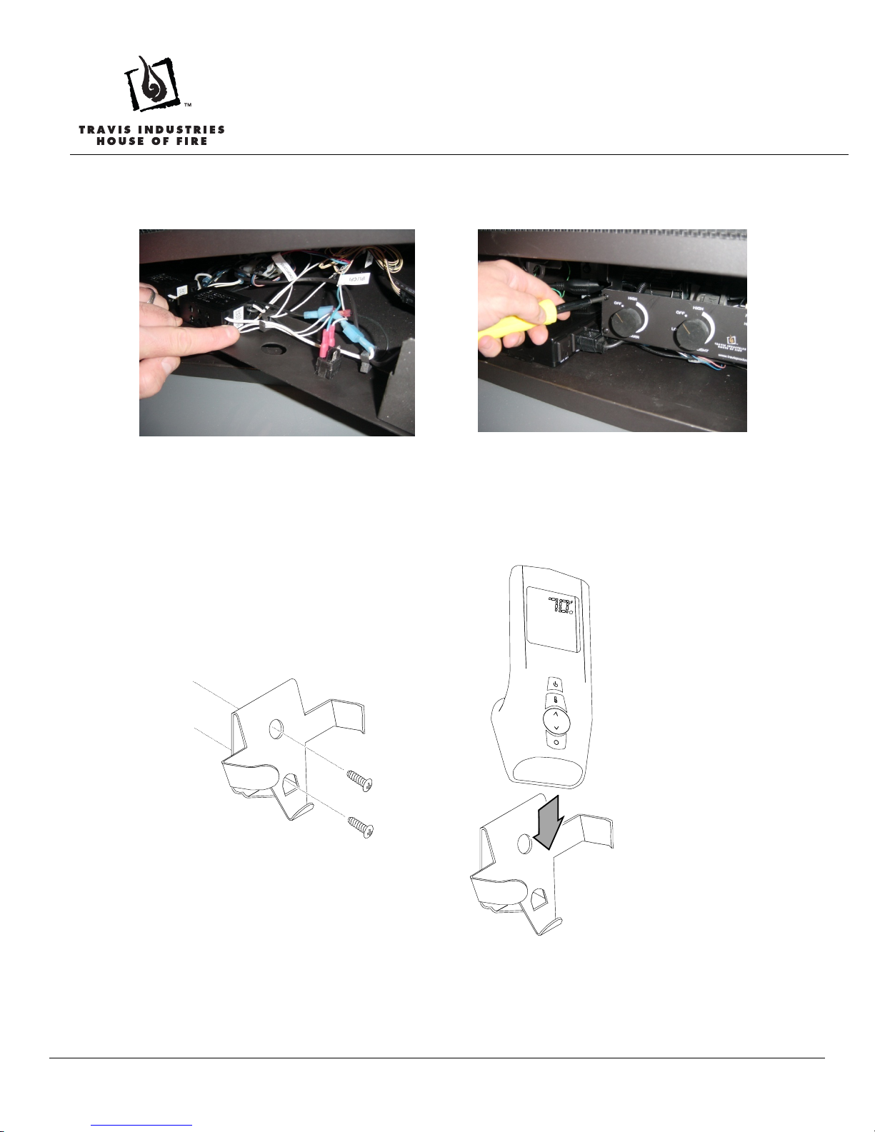
16 Pull the “RECEIVER” connector through the control panel and attach to the receiver (see Figure
21). Then attach the receiver to the control panel with the two #8 machine screws (see Figure 22).
Figure 21
Figure 22
17 Place batteries into the receiver and transmitter (see Figure 23). Calibrate the receiver to the
transmitter (see Figure 24 - use a paperclip to press the “PRG” button, let it beep, then press any
button on the transmitter – the receiver should beep 5 times – see the operating instructions for
further details).
Figure 23
Figure 24
18 Place the receiver coverplate (and switch) over the receiver (see Figure 25) and attach with the
two screws included with the receiver (see Figure 26)
Figure 25
Figure 26

GreenSmart™ Remote – Export Version
SKU 99300699 (NG) SKU 99300698 (LP)
Page 9 of 15 9/25/09 - 17601590 © Travis Industries, Inc.
19 Clip any excess wiring into the wire clips on the back of the control panel (see Figure 27). Use
the included wire ties, if necessary, to keep all wiring from contacting any hot or moving
components. Re-attach the control panel (see Figure 28) and shroud (see Figure 1).
Figure 27
Figure 28
20 A wall mount is included with this kit for the remote. It may be mounted to the wall for easy
access and storage. Use the included drywall anchors (and screws) to secure it to the wall (see
Figure 29).
Figure 29
23 Restore power to the fireplace and test operation of the remote (see the instructions included
with1the remote).

GreenSmart™ Remote – Export Version
SKU 99300699 (NG) SKU 99300698 (LP)
Page 10 of 15 9/25/09 - 17601590 © Travis Industries, Inc.
Battery Installation
Transmitter Battery Installation
Install the three included AAA batteries into the remote (see Figure 30).
°F
AAA Battery
AAA Battery
AAA Battery
Figure 30
Receiver Battery Installation
Install four AA batteries into the receiver (see Figure 31). You can use the batteries from the battery
backup tray on the appliance. See the installation instructions for details. These batteries control the
comfort control and act as a power-backup in case the household (AC) current goes out.
AA Battery
AA Battery
AA Battery
AA Battery
Figure 31

GreenSmart™ Remote – Export Version
SKU 99300699 (NG) SKU 99300698 (LP)
Page 11 of 15 9/25/09 - 17601590 © Travis Industries, Inc.
Set-Up
Synchronize the Transmitter to the Remote
The transmitter will need to be synchronized to the receiver before the remote will work correctly.
Synchronizing is done in the following two steps below (see Figure 32):
a) Press the PRG (Program) button on the receiver using a paperclip or equivalent device (receiver
will beep 3 times).
b) Press the “ON” button on the transmitter (receiver will beep 4 times).
°F
"Beep"
"Beep"
"Beep"
"Beep"
"Beep"
"Beep"
“Beep”
Figure 32
NOTE: If power is cut off to the receiver for an extended period of time, you may need to re-synchronize
the remote.
Direct Fireplace Operation
The fireplace may be directly operated from the receiver. The three positions are below (see Figure 33):
ON – Fireplace burner turns on (regardless of transmitter settings).
OFF – Fireplace burner turns off (regardless of transmitter settings).
REMOTE – Fireplace is controlled by the transmitter.
ON
REMOTE
OFF PRG
Figure 33
NOTE: When the receiver switch is turned to ON or OFF, the mode settings (Flame Height, Comfort
Control) will remain in the same state as before the switch was moved (i.e.: the receiver “remembers” the
last setting). If you wish to adjust the mode settings use the transmitter mode button to adjust the
settings (see “Mode Controls” on page 14). The thermostat and burner on/off operating functions will not
work on the transmitter.

GreenSmart™ Remote – Export Version
SKU 99300699 (NG) SKU 99300698 (LP)
Page 12 of 15 9/25/09 - 17601590 © Travis Industries, Inc.
Remote Operation
Once the receiver is switched to “REMOTE” the transmitter operates the fireplace. Once you understand
how the transmitter works, you will be able to operate your fireplace quickly and easily.
Display Overview
The transmitter display has four main sections (see Figure 34).
ON
F
MAX
Thermostat Display
Room Temperature Display
Read-Out (Thermostat Setting, Function, etc.)
Mode Display (Flame Height, Comfort Control)
Figure 34
Listen for the “Beep”
Each time you press a button on the transmitter that controls the fireplace, a “beep” will come from the
fireplace. When you change thermostat target settings the fireplace will not beep.
NOTE: When the receiver batteries start to get low, the receiver will beep intermittently. When the
batteries are nearly depleted, the receiver will no longer beep. See “Receiver Batteries” on page 15).

GreenSmart™ Remote – Export Version
SKU 99300699 (NG) SKU 99300698 (LP)
Page 13 of 15 9/25/09 - 17601590 © Travis Industries, Inc.
Manual On-Off / Smart Thermostat / Standard Thermostat
Use the thermostat button to cycle through the three thermostat settings (see Figure 35).
OFF
ON SMART
ON
F
Look here for the
thermostat setting.
Press the thermostat button to cycle
through the thermostat settings.
Figure 35
MANUAL ON/OFF – The burner will turn on and off using the remote (see Figure 36). Press the
On/Off button to control the burner. When off, the display will only show the current temperature.
OFF
F
When in manual setting, the
word “OFF” will appear here.
MAX
Figure 36
SMART THERMOSTAT – While in smart thermostat, the transmitter will control the burner to
achieve the target temperature (see Figure 37 below). Flame height will be adjusted up or down
to allow operation without turning the burner on and off (also called “smart modulation). To adjust
the target temperature, press the up and down buttons until a suitable temperature is achieved.
ON
F
When in standard thermostat
setting, the word “ON” will
appear here.
This is the target temperature
on the read-out. Use the up
or down buttons to adjust the
target temperature.
Figure 37
STANDARD THERMOSTAT - While in standard thermostat setting, the transmitter will turn the
burner on and off to achieve the target temperature (see Figure 38 below). To adjust the target
temperature, press the up and down buttons until a suitable temperature is achieved.
F
When in smart thermostat
setting, the word “SMART”
will appear here.
This is the target temperature
on the read-out. Use the up
or down buttons to adjust the
target temperature.
SMART
Figure 38
NOTE: if the transmitter batteries go dead while in thermostat setting (standard or smart), the appliance
will shut off after approximately 24 hours.

GreenSmart™ Remote – Export Version
SKU 99300699 (NG) SKU 99300698 (LP)
Page 14 of 15 9/25/09 - 17601590 © Travis Industries, Inc.
Mode Controls (Flame, Comfort Control)
Use the mode button to cycle through the two mode controls (see Figure 39 below).
OFF
F
Look here for
mode controls.
Press the mode button to cycle through the mode settings.
Flame
Height Comfort
Control
Figure 39
Flame Height
Flame height may be controlled using the up and down buttons when in Flame Height Mode (see Figure
40 below). The center display will display the 7 settings, from “OFF” to “HI” for full on.
NOTE: Flame height may not be adjusted if operating in Smart Thermostat setting.
OFF
F
When in flame height
mode, this icon will
appear darkened.
MAX
This is the flame height read-
out. Use the up or down
buttons to adjust the flame
height (7 settings).
High
Medium
Off
Figure 40
Comfort Control (rear burner)
The comfort control (rear burner) may be turned on and off using the up and down buttons when in
Comfort Control Mode (see Figure 41). The center display will display either “ON” or “OFF”.
OFF
F
When in comfort
control mode, this
icon will appear
darkened.
This is the comfort control
read-out. Use the up button
to turn on, down button to turn
off (2 settings).
On
Off
Figure 41

GreenSmart™ Remote – Export Version
SKU 99300699 (NG) SKU 99300698 (LP)
Page 15 of 15 9/25/09 - 17601590 © Travis Industries, Inc.
Low Battery Indicator
Transmitter Batteries
The transmitter has a battery-level indicator. When it indicates low battery voltage (see Figure 42 below),
install four new AAA alkaline batteries into the transmitter (see “Transmitter Battery Installation” on page
10).
ON
F
Low Battery Indicator
MAX
Figure 42
Receiver Batteries
The receiver will “beep” periodically when the receiver batteries go low. Install four new AA alkaline
batteries into the receiver when this occurs (see “Receiver Battery Installation” on page 10). In
applications where the appliance is required to provide heat, we recommend replacing the batteries
before each heating season.
Child Proof Feature
The child proof feature disables the control buttons, preventing un-wanted use of the remote.
Press both the MODE and UP buttons simultaneously to turn this feature on and off (see Figure
43 below).
HINT: This feature is especially useful while using the thermostat setting.
ON
F
Child Proof Indicator
MAX
Figure 43
Power Outages
The remote will work if household current (AC power) is disconnected. The batteries inside the receiver
will continue to power the heater but the accent light and blower will not operate.
This manual suits for next models
1
Table of contents
Other Travis Industries Remote Control manuals
Popular Remote Control manuals by other brands

Alfaled
Alfaled AFR-1-1 quick start guide

BNF
BNF DX6E instruction manual

American Lighting
American Lighting TRULUX TWRF-3AAA installation instructions

Boston Scientific
Boston Scientific DB-5542-1A Directions for use

Cardin Elettronica
Cardin Elettronica S48D RX16-100 manual

Panasonic
Panasonic CZ-RWSD2U installation instructions