Trelawny A45 User manual

A45 Industrial Dust Collector (Bin)
Operation and Maintenance Manual
www.trelawnyspt.co.uk

OPERATION
Foreword
Thank you for your purchase of the
TRELAWNY Professional use A45
Industrial Vacuum Cleaner.
This manual contains the necessary
maintenance information for you to
ensure proper operation and care for
this machine.
It is essential for you to read
through this manuals thoroughly.
In the unlikely event that you
experience problems with your A45
Vacuum, please do not hesitate to
contact your local Trelawny dealer or
agent. We always welcome
feedback and comments from our
valued customers.
General Information
Before operating, performing
maintenance or repairing the A45
Industrial Vacuum Cleaner, this
manual must be read and
understood by the operator, if in any
doubt, ask your supervisor before
using this equipment.
Local safety regulations must be
followed at all times. Failure to follow
these instructions could result in
damage to the A45 Vacuum and/or
personal injury.
Trelawny SPT Limited disclaims all
responsibility for damage to persons
or objects arising as a consequence
of incorrect handling of the machine,
failure to inspect the machine for
damage or other faults that may
influence the operation prior to
starting work, or failure to follow the
safety regulations listed or applicable
to the job site.
This machine is primarily designed
for the containment of nuisance dust
and dust collection.
HEPA filtered vacuum system is
available, which will contain 99.97%
(DOP) of all air borne dust when
removing toxic or contaminated
products.
It can be used both indoors and
outside in dry weather only.
This machine is not water proof,
avoid splashing with water if using to
collect fluid spills.
Safety
The person in charge of safety shall
be responsible for informing workers
about the risks associated with
vacuum cleaner operations.
Train operators in the correct use
and maintenance of the vacuum in
order to protect themselves and
others from hazards.
Failure to observe basic safety
regulations and precautions could
cause accidents during the vacuum
cleaners operation, maintenance or
repair.
Trelawny shall under no
circumstances be deemed liable for
accidents or damage caused by use
of the vacuum cleaner by personnel
not properly trained or who use it in
an improper manner.
The safety precautions and warning
notices are indicated in this manual
and on the product.
Unless these hazard messages are
heeded, the operator could become
involved in accidents with serious
consequences for him/herself and
others.
Trelawny cannot foresee all possible
circumstances capable of
representing a potential hazard,
therefore the warnings in this manual
and on the product should not be
deemed exhaustive.
Only ever use original Trelawny
spare parts
Trelawny declines all liability in
the event of non-original spare
parts being used.
In the event of tools, procedures or
work methods used that are not
explicitly recommended by Trelawny,
ensure no hazards exist for the
operators and others.
Further advice is available from our
Technical Department.
The employer must inform and train
the user according to the provisions
of applicable local laws.
Before using the machine, prepare
and train yourself by reading this
manual carefully.
Use of the machine by untrained and
unauthorised persons is forbidden.
Do not use the machine to vacuum
toxic substances unless it has been
equipped with the special filters
required for the specific type of dust.
Such filters must be explicitly
requested by you.
Do not vacuum flammable materials
or substances or which could cause
explosions (fuels, solvents, etc.). To
vacuum such materials, the machine
must be built with anti-explosion
motor and electric system and this
must be requested by you explicitly.
Do not vacuum corrosive substances
unless the machine is equipped with
containers suitable for this purpose
(Stainless-steel AISI 304).
Use of the machine without the
supplied filters is not recommended.
If the machine is used to vacuum
toxic/harmful substances, the
container must be emptied and the
filters cleaned using adequate
Personal Protection Equipment.
This machines motor casing
contains electrical components
which must not be dismantled by the
user.
When using the machine, be aware
of other people around you.
Use the machine cautiously on
slopes and ramps. Do not change
direction on gradients.
Make sure the parked machine
remains stable by operating the
braked wheel.
Do not open the vacuum container
with the motor running.
Pre-Start Check
Check all bolts and screws for
tightness. Ensure that all fittings are
secure.
This specific vacuum cleaner model
has been designed, built and
protected for vacuuming dusts and
solid and also liquids, but only
within the capacity of the
container.
SEE BELOW for filter options.
To ensure the correct operation of
the vacuum cleaner, this must be
positioned protected against
atmospheric agents (rain, hail, snow,
fog, dusts in suspension, etc.) with
an environmental running
temperature between 5°C and 45°C
and relative humidity not above 70%.
The work environment must be
clean, well-enough lit and devoid of
explosive atmosphere.
The vacuum cleaner must not be
used in environments containing
substances in the form of liquids that
could vaporise at room temperature
and flammable dusts and gas.
All cables should be fully uncoiled
and never left wrapped around cable
reels or tied in loops.
OPTIONAL FILTERS
Besides the optional HEPA filter
(303.5262), and depending on the
dust to be vacuumed, the following
filters are also available:
Antistatic filter
For electrostatic dust.
Nomex filter
For hot dusts up to 240°.
Polyester filter cat.M
For very fine dusts, the polyester
filter are BIA institute certified.
OPERATION
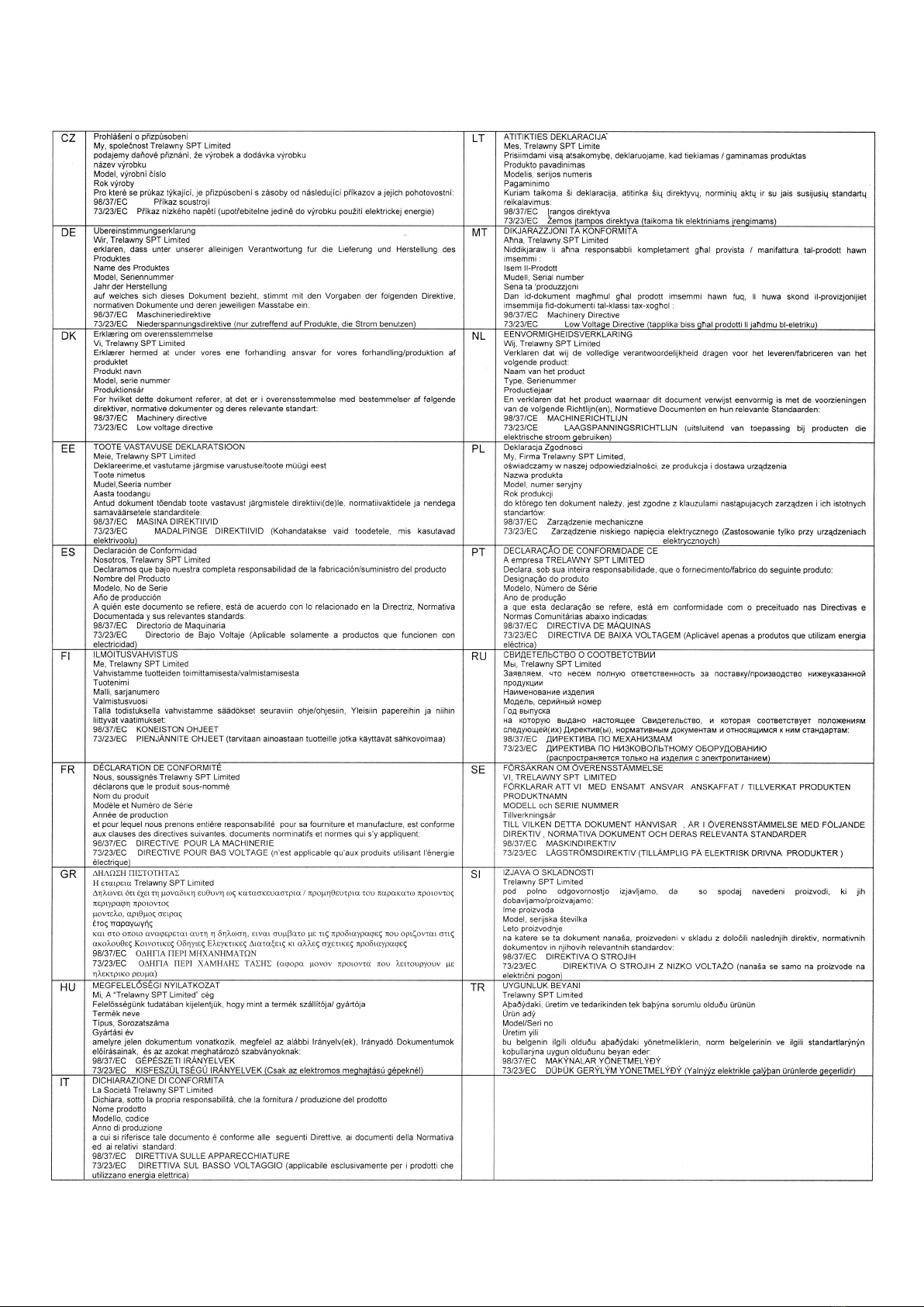
REMOVABLE CYCLONE
The cyclone is a treated steel cone
that separates the filtering chamber
from the container. This is positioned
above the vacuum inlet and below
the filter. Its job is to protect the filter
from hot or sharp solid bodies and
nebulised liquids.
BAG RETENTION RING
This optional can be requested when
the vacuumed material is to be
collected in a disposable nylon bag
fitted in the container. It allows
keeping open the nylon bag, which is
subject to vacuum, for correct use.
Part numbers: 303.5474 (for liquids
and solids) and 303.5478 (for dust)
Part number:
303.5479
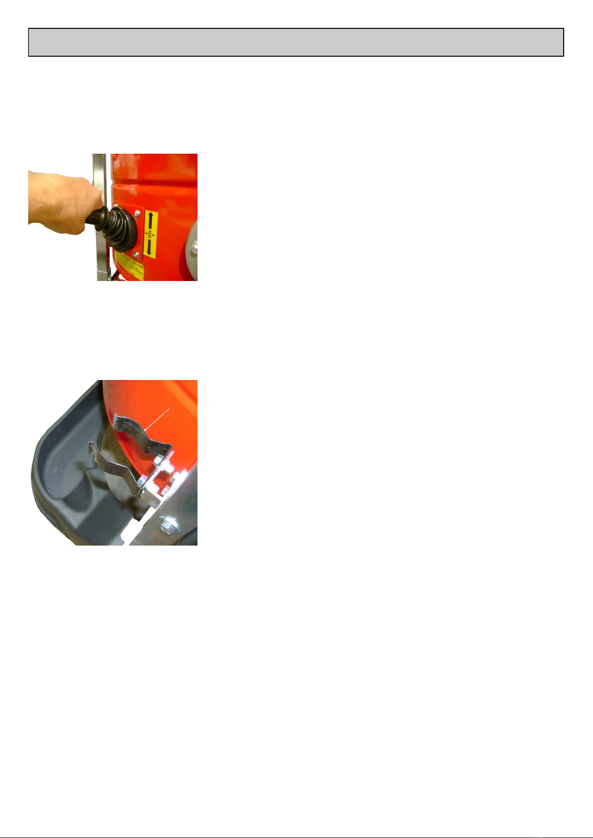
WET/DRY PICKUP
The bracket of the
WET-DRY
accessory must be
secured to the
vacuum cleaner
frame by means of
the special front
mounting point (A).
SIEVE CONTAINER
This accessory separates the liquids
from the solids. The solids remain in
the top gridded basket, while the
liquids deposit on the bottom of the
container.
Part number:
303.5472
Part Number:
303.5471
To change the filter, switch off the
vacuum
cleaner
and
remove
the plug
from the
power
socket,
release
and
remove the upper cap and then
loosen nut (A).

OPERATION
Starting
Description of controls
1
2
34
5
1) START/STOP switch motor 1
2) START/STOP switch motor 2
3) START/STOP switch motor 3
4) Green light POWER ON
5) Vacuum meter
4
3
7
6
2
5
1) Motor unit
2) On/Off Switches & Gauge
3) Release Fasteners
4) Removable Vacuum Material
Container
5) Filter Chamber
6) Filter Shaker Lever
7) Vacuum Connection
8) Accessory Tray
9) Braked Castor Wheel
10) Removable Material Container
11) Cable storage Bracket
12) Push Handle
1
When contacting Trelawny SPT Ltd
or thier agent, always quote the
details shown on the vacuum
cleaner serial plate.
240v Motor
Take particular care when using
240v Machines, ensure that the
electrical supply is earthed and that
breakers and fuses are correct for
the loading.
The 240v motor requires the
minimum of a 20amp, 220v power
supply.
To avoid voltage drop, always use
the shortest possible length of
extension cable.
Maximum length of cable 30 meters.
Fit the accessory required for the
type of vacuuming operation on the
opposite end of the hose.
Note: Standard accessories
(reducers, hoses, nozzles) are
included with the vacuum. Any other
accessories must be specified and
ordered separately.
Fit the supplied connector on the
pipe union.
Fit the supplied pipe in the
connector.
Make sure the power supply
corresponds to the voltage and
frequency indicated on the vacuum
cleaner plate.
IMPORTANT: Do not plug in the
power socket with wet hands
In the event of an extension being
used, make sure this is in perfect
condition, in compliance with EC
standards and with cable cross
section suitable for the power input
of the vacuum cleaner.
Operation
Lock the front castor wheel (7).
Grip one end of the flexible hose
complete with selected accessory.
To start, switch on individual motors
as required, and start vacuuming.
To stop the vacuum cleaner, return
all the switches to the off position.
Caution:
Before switching the vacuum cleaner
back on, ensure the motors have
come to a complete halt.
After finishing work, disconnect the
vacuum cleaner from the power
supply.
Lift the handle in the bottom part of
the cleaner to release and remove
the container.
Empty the contents of the container
into a special waste disposal
container in accordance with local
laws applicable in the country where
the vacuum cleaner is used.
8
9
10
11
Release lever
OPERATION & MAINTENANCE
MAINTENANCE
This section describes the control
and special maintenance operations
crucial for keeping the vacuum
cleaner in perfect working condition.
Any other jobs which might be
necessary to eliminate operating
faults must be expressly authorised
by the manufacturer. In such cases,
always supply the identification
details of the cleaner.
In the case of major repairs, it is best
to contact an authorised dealer.
General safety
precautions
Maintenance jobs must always be
performed by skilled technicians,
trained to carry out their specific
jobs. In the case of this machine,
these are:
Mechanical maintenance
Electrical maintenance
The Safety Manager has the precise
duty of determining the professional
capacities and skills of such
persons.
Before doing any maintenance job,
the safety manager must:
Make sure there are no unauthorised
persons in the work area.
Make sure the necessary tools are
on hand and that these are in good
condition.
Make sure that lighting is adequate.
Make sure the maintenance
engineer is equipped with all
approved individual protection
devices needed for the specific
operation (gloves, eyewear, shoes,
etc.)
Make sure the maintenance
engineer has carefully read the
instructions contained in this manual
and knows how the vacuum cleaner
works.
Using the filter cleaning
system.
These following operations must
only be performed with the machine
switched off once the motor has
come to a complete halt.
Before carrying out a maintenance
job, the maintenance engineer must:
Disconnect the plug from the power
socket.
Work done on motors or other
electrical component parts must only
be performed by a specifically
trained electrician, authorised by the
Safety Manager.
Always use tools that are in perfect
condition and specifically made for
the operation to be done.
The use of unsuitable tools or tools
not in good condition could cause
serious damage.
Maintenance checks
For efficient vacuum cleaner
operation, a number of controls
are best made periodically:
Check to see whether the filter is
worn or has become too permeable.
Make sure the sealing gaskets of the
motor head base and of the
filter-holder ring and of the container
are working efficiently.
The electrical parts (plugs, switches,
cables, etc.) must not be faulty.
The screws and nuts must always be
tight.
Make sure the container is not
overfull.
Check the integrity of the flexible
vacuum hose and accessories to be
used.
If the flexible hose is perforated, the
power of the cleaner will be reduced
and dust and liquids will leak into the
environment.
This should be emptied when the
vacuumed material has reached 3/4
of maximum capacity.
On the front of the vacuum cleaner is
a vacuum meter indicating the
degree of vacuum inside the vacuum
cleaner.
If, with the vacuum cleaner working
and the vacuum inlet free, the
vacuum meter lever indicates an
irregular depression level, the filter
will have to be shaken by means of
the special lever.
If the arrow of the vacuum meter
stays in the red area even after
cleaning the filter, the hose or
suction accessory could be blocked.
In this case, clean and remove the
blockage.
The filter cleaning system is best
operated every time before use and
after prolonged operation.
For greater convenience, the most
frequently used accessories can be
placed in the special accessory
basket (A) and tube holder (B).
A
B

Release the levers that hold the
motor head.
MAINTENANCE
Lift the motor head by means of the
handles provided and rest this on a
support bench, take not to damage
the power cable.
Remove from underneath the
vacuum cleaner the pin (A) and
spring pin (B) that fasten the filter to
the shaking lever.
Lift out the filter complete with its
support.
Unscrew the clamp and remove the
support ring with seal.
Undo the tied knots from inside (A)
and the underside, then remove the
pocket filter.
Fit the new filter, put everything back
together carefully securing all ties
and fit the cap back on.
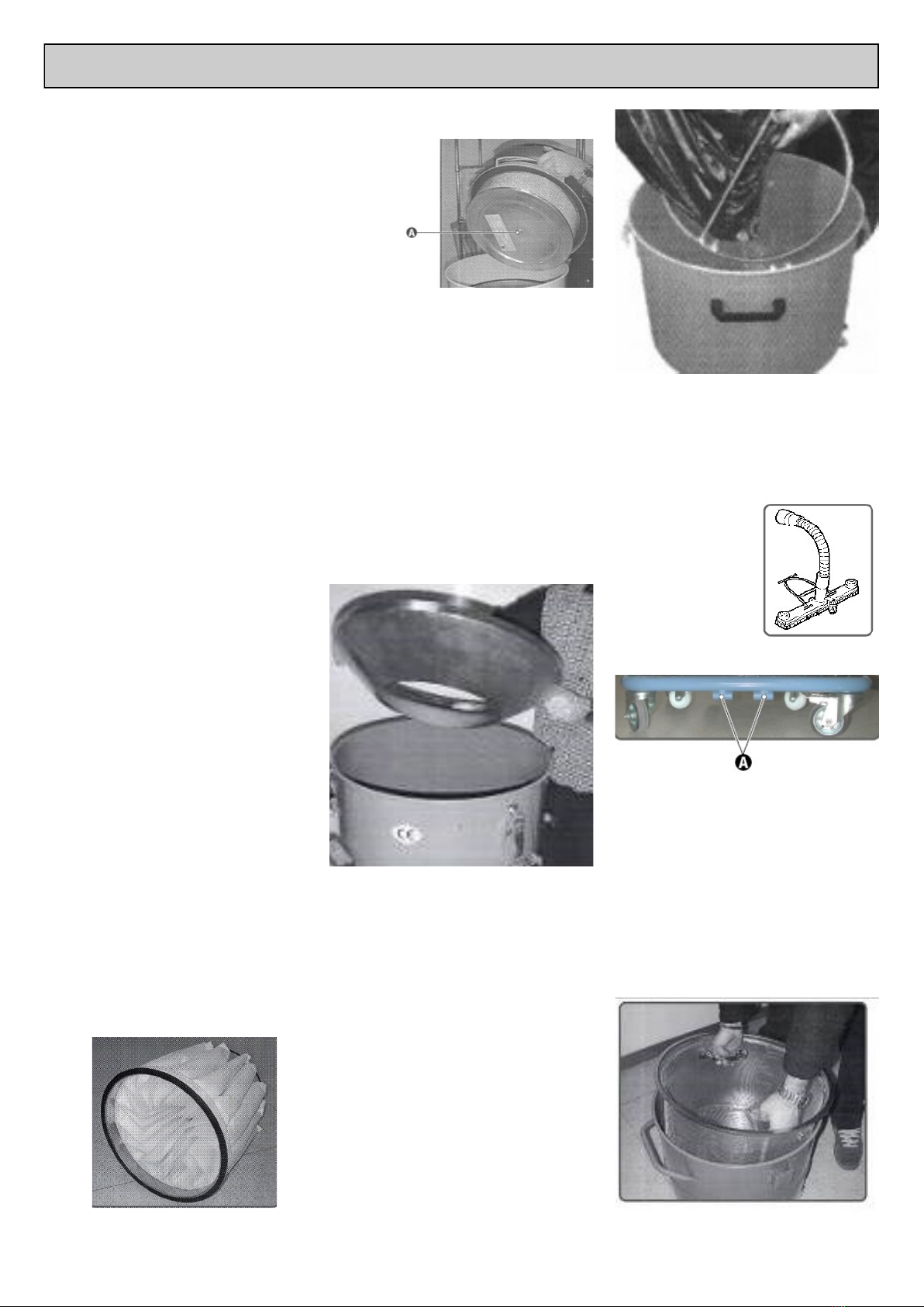
The container locking operation
must be performed by one person
only, who must lower the lever with
both hands to lock the canister in
position.
Replacing the filters
To replace the filters, proceed as
follows:
Turn off the vacuum cleaner by
pressing down the motor STOP
switches.
Disconnect the vacuum cleaner plug
from the power socket.
Ensure front wheels are locked.
Lift the lever that locks the container.
Remove the container
Important:
All material trapped and contained
within the filter must be disposed of
according the local legislation
NOTE:
Do not place hands on sides of
container near the guide pins
while re-installing.
Perform the container locking
operation by means of the lever
located on the front, USE BOTH
HANDS !!
A
B
A
DOWN
UP
RECOMMENDED PARTS AND FAULT FINDING
Machine Storage
Remove the filter and clean it, empty the container and store the vacuum cleaner in a place protected against
condensation and at a temperature between 0°C and 40°C.
Cover with a nylon sheet to prevent accumulation of dust.
Scrapping
In case of scrapping, all the component parts of the vacuum cleaner will have to be disposed of through adequate
disposal channels in accordance with applicable legislation.
Before scrapping, all plastic and rubber parts will have to be separated from the electrical material.
Most parts made from plastic, aluminium, copper or steel are suitable for recycling.
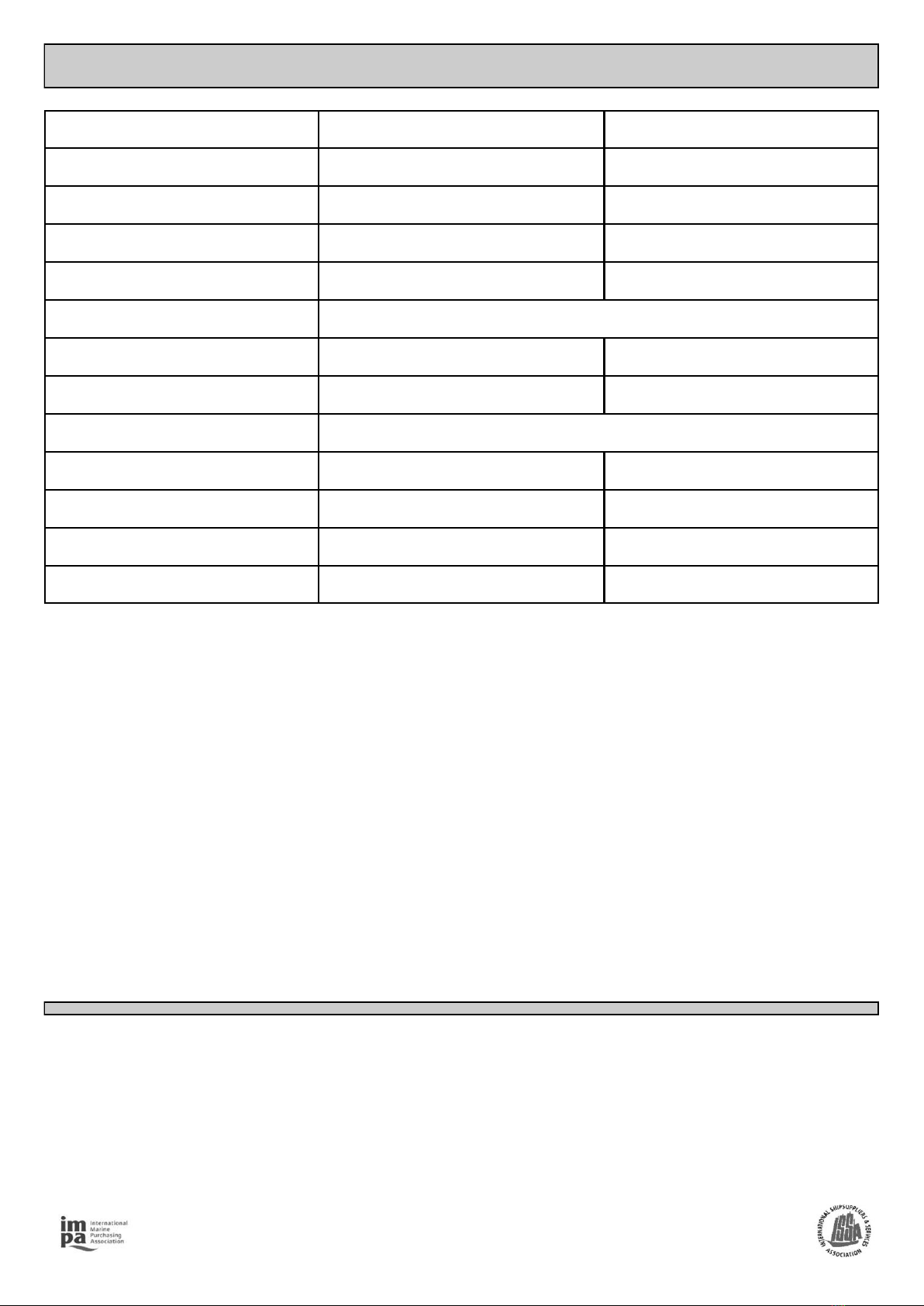
FAULT CAUSE ACTION
The cleaner fails to
start.
No power. Check the power mains supply.
Check the integrity of the plug and power
cable.
Thermal magnetic switch tripped Reset the thermal magnetic switch.
Loose wiring, incorrect voltage, or blown
fuse.
Check connections and power supply or
replace fuse.
Dust is leaking out Perforated vacuum pipe. Replace the pipe.
Perforated filter. Replace the filter.
Filter unsuitable for type of job. Fit a suitable filter for the type of material to be
vacuumed.
The vacuum cleaner
does not work as it
should.
Pipe perforated or blocked. Check the pipe and, if necessary, replace.
Container full Empty container.
Filter blocked. Replace filter.
Seals worn. Clean the filter and if necessary change it.
Air leak. Check for any air leaks out of closing
fasteners, tightening screws, container or filter
chamber.
If problem has not been cured by any of the above actions, contact your local Trelawny SPT dealership for assistance.
PART NUMBER DESCRIPTION
303.5282 Polyester Filter with 14 Pockets 20000 CM2 Ø500
303.5289 Filter-Holder Seal Ø500
303.5493 Filter Clamp Ø500
303.5293 Container / Chamber Seal Ø500
303.5306 Adhesive Gasket
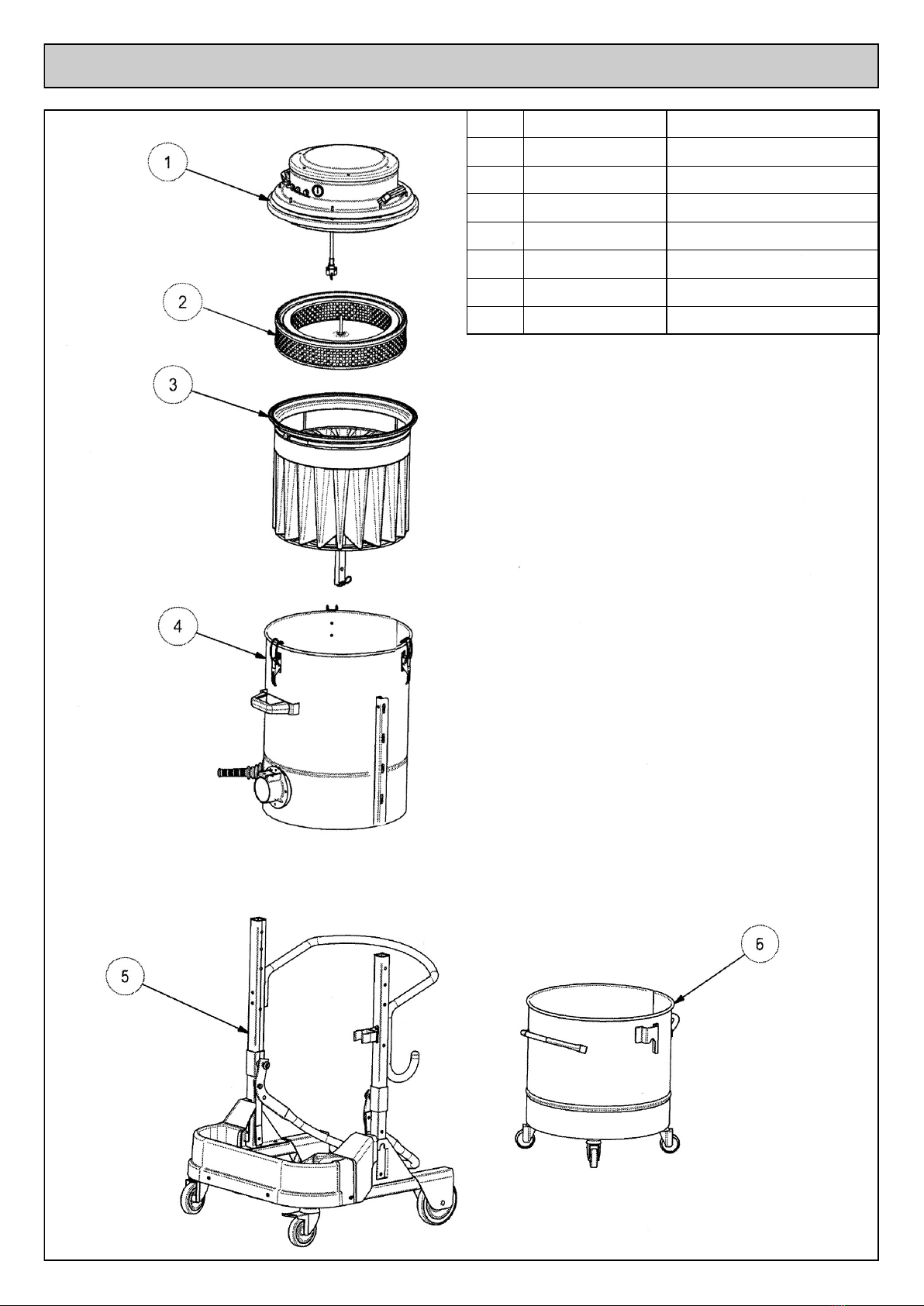
EXPLODED VIEW - MACHINE
Item Part No Description
1303.5367 110v Motor Head Assembly
303.5366 230v Motor Head Assembly
2303.5373 HEPA Filter Kit
3303.5368 Filter Assembly
4303.5369 Chamber Assembly
5303.5398 Frame Assembly
6303.5376 Container Assembly

EXPLODED VIEW - MOTOR HEAD

EXPLODED VIEW - MOTOR HEAD
Item Part No Description Item Part No Description
1303.5090 Motor Head Cover 22 303.5514 1/8” Connection
2303.5290 Cover Noise Damping Material 23 303.5107 Motor Fastener
3303.5498 Filter Ring (3 x required) 24 303.5292 Motor Fastener Noise Damping Material
4303.5535 Cooling Ring 25 303.5518 Motor Head Spacer (Male/Male)
5303.5529 Motor Head Spacer (6 x required) 26 303.5582 Motor Head Spacer (Male/Female)
6303.5495 Handle (2 x required) 27 303.5515 Motor Head Spacer (2 x Female/Female)
7303.5197 230v Motor Head Wiring Kit 28 303.5540 Plastic Motor Ring (3 x required)
303.5248 110v Motor Head Wiring (2 x Black Cable) 29 303.5300 Gasket (6 x required)
303.5249 110v Motor Head Wiring (2 x Blue Cable) 30 303.5285 230v Electric Motor (3 x required)
8303.5130 230v Switch (3 x required) 303.5284 110v Electric Motor (3 x required)
9303.5131 Switch Rubber Covers (3 x required) 31 303.5520 Bottom Valve Plate (3 x required)
10 303.5245 Chrome Nut for Light 32 303.5525 Motor Bottom Plate (3 x required)
11 303.5132 Red Light 33 303.5350 Motor Bottom Plate Gasket (3 x required)
12 303.5178 Vacuum Gauge 34 303.5295 Base Plate Noise Damping Material
13 303.5157 Straight Pipe Coupling 35 303.5497 Master Motor Head Spacer (8 x required)
14 303.5215 Nylon Pipe (0.3m required) 36 303.5108 Base Plate
15 303.5195 Plastic Nut 37 303.5150 Fuse Cover (6 x required)
16 303.5135 Plastic Cable Fastener 38 303.5145 Fuse 10amp (6 x required) 230v Machines))
17 303.5137 230v Cable (10mtr) 303.5146 Fuse 15amp (6 x required) 110v Machines))
303.5138 110v Cable (10mtr) 39 303.5230 Fuse Holder
18 303.5104 Cover 40 303.5197 230v Motor Wiring Kit
19 303.5180 Cable Fastener Support 303.5246 120v Motor Wiring Kit
20 303.5291 Cover Noise Damping Material 41 303.5230 30amp 250v Fuse Holder
21 303.5160 Swivel Elbow (push in fitting)

EXPLODED VIEW - FILTER UNIT
Item Part No Description
1303.5289 Filter Gasket
2303.5507 Filter Holding Ring
3303.5493 Filter Clamp
4303.5501 Filter Separator Cage
5303.5282 14 Pocket “M” Polyester Filter
6303.5502 Filter Shaker Cage
7303.5503 Cage Lock Pin
8303.5581 R-Clip

EXPLODED VIEW - FILTER CANISTER
Item Part No Description
1303.5490 Toggle Clamp (3 x required)
2303.5611 Chamber
3303.5496 Right “U” Channel Mounting Bracket
4303.5306 Adhesive Gasket
5303.5500 Deflector
6303.5305 Deflector Gasket
7303.5499 Inlet Connector
8303.5504 Spring
9303.5506 Connector Latch
10 303.5508 Latch Pin
11 303.5491 Filter Shaker Handle
12 303.5492 Filter Shaker Lever Boot
13 303.5488 Filter Shaker Lever
14 303.5489 Filter Shaker Flange
15 303.4588 Canister Handle
16 303.5494 Left “U” Channel Mounting Bracket

EXPLODED VIEW - FRAME
Item Part No Description
1303.5509 End Caps (2 x required)
2303.5523 Frame Stanchion (2 x required)
3303.5521 Push Handle
4303.5519 Handle End Cap
5303.5513 Container Lift Lever
6303.5436 Large Wheel (2 x required)
7303.5437 Wheel Axle (2 x required)
8303.5451 Castor Wheel with brake
9303.5453 Castor Wheel
10 303.5524 Accessories Holder Tray
11 303.5614 Frame Base
12 303.5455 Coach Bolt (2 x required)
13 303.5541 Spring Clip
14 303.5542 Spring Clip Mounting Bracket
15 303.5512 Slide Bracket (2 x required)
16 303.5511 Lift Lever Fulcrum (2 x required)
TECHNICAL SPECIFICATIONS
This tool has been designed and produced in accordance with the following directives:
·2006/42/CE Machine directive
·2004/108/CE Electromagnetic compatibility directive
·2006/95/CE Low-voltage directive
If your company has any problem with our products or would like to discuss the possibility of an improvement being made
to them, then please do not hesitate to contact us. Your comments are both important and appreciated.
All rights reserved. Any unauthorised use or copying of the contents or part thereof is prohibited.
This applies to trademarks, model denominations, part numbers and drawings.
Use only genuine Trelawny spares.
The use of non-Trelawny spare parts invalidates the warranty.
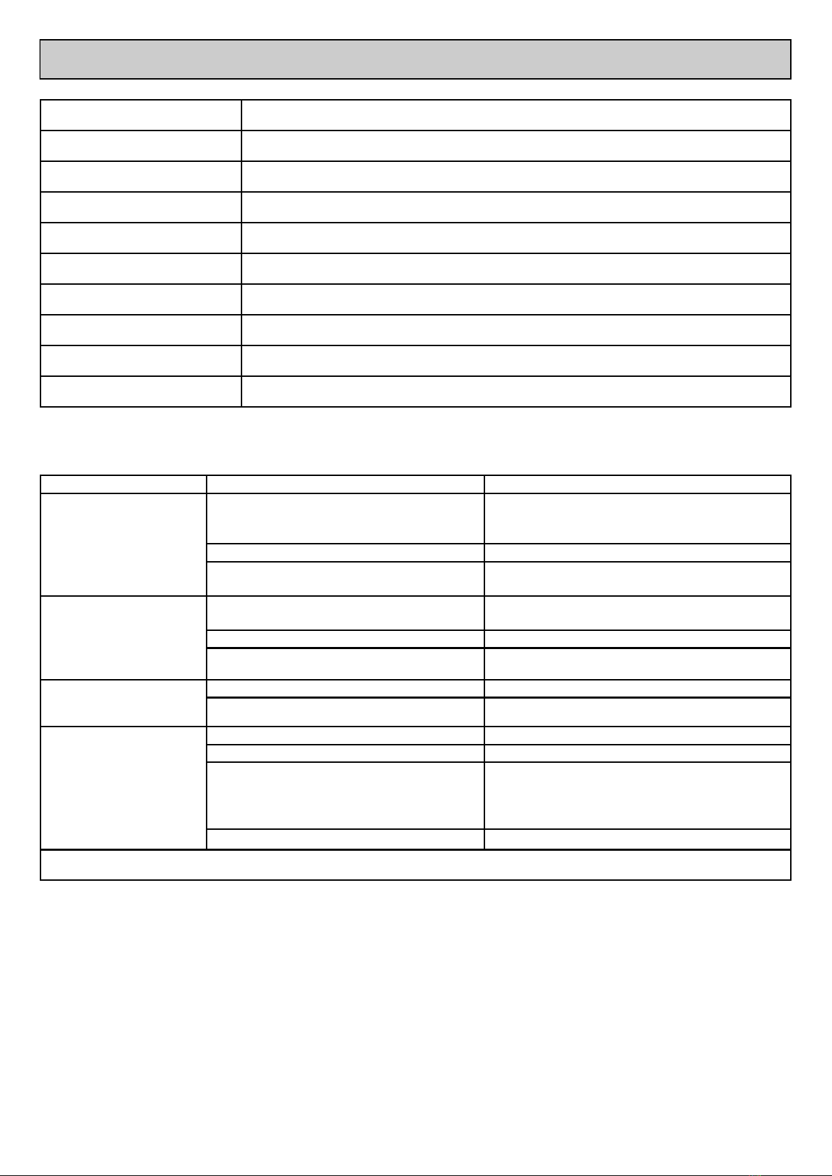
Model 110v 230v
Power (Watts) 3000 3450
Vacuum rate (Mm/H2O) 2.250 2.500
Max. Air flow (M3/h) 525 540
Noise level dB(A) 76 76
Filter type/ material Polyester M
Filtering surface (cm2)20,000 20,000
Capacity (Lt) 60 60
Vacuum inlet Ø 80
Dimensions (cm.) 58 x 60 58 x 60
Height (cm.) 135 135
Weight (Kg) 65 65
Package size / weight 65 x 65 x175mm 75kg
NOTES

NOTES
NOTES

Trelawny SPT Ltd
13 Highdown Road, Sydenham Industrial Estate, Leamington Spa,
Warwickshire, CV31 1XT, United Kingdom
Telephone: +44 (0)1926 883781 - Fax: +44 (0)1926 450352
Email: sales@trelawny.co.uk
© TSPT UK 2012 Part No: 735.6045 issue 10.8.17 www.trelawnyspt.co.uk
Other manuals for A45
1
Table of contents
Other Trelawny Dust Collector manuals


Popular Dust Collector manuals by other brands

Donaldson Torit
Donaldson Torit E-100 Installation and operation manual

Jet EQUIPMENT & TOOLS
Jet EQUIPMENT & TOOLS DC-1900C owner's manual

Nederman
Nederman E-PAK 300 DX instruction manual

DustBull
DustBull D1765 owner's manual

Grizzly
Grizzly G1163 owner's manual

Metabo
Metabo SPA 1700 D/W Manuale di istruzioni

Grizzly
Grizzly G0672 owner's manual

Metabo
Metabo SPA 1200 operating instructions

IST
IST ISTblast DC Series instruction manual

Oneida Air Systems
Oneida Air Systems V-System XXVS300035 owner's manual

Conair
Conair Dust Collector Size 3 user guide

ENVIROSYSTEMS
ENVIROSYSTEMS AIRWALL MD INSTALLATION, OPERATION, MAINTENANCE AND REPLACEMENT PARTS MANUAL


