Trelawny Challenger VL203 Installation guide
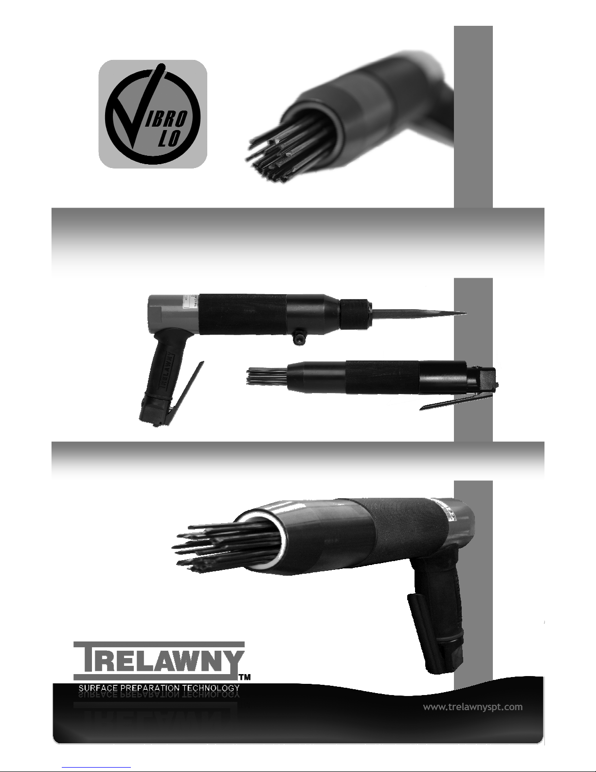
VL203/223 & 303 CHALLENGER
NEEDLE & CHISEL SCALERS
OPERATION & MAINTENANCE

OPERATION
General Informat on
Before operating, performing maintenance or repairing
the Challenger VL203/223 & 303 Needle/Chisel Scalers,
this manual must be read and understood If in any doubt,
ask your supervisor before using this equipment
Local safety regulations must be followed at all times
Failure to follow these instructions could result in damage
to the Scaler and/or personal injury
Operators should be familiar with the data given in the
specification section Please keep these instructions in a
safe and accessible place
Trelawny SPT Limited disclaims all responsibility for
damage to persons or objects arising as a consequence
of incorrect handling of the tool, failure to inspect the tool
for damage or other faults that may influence the
operation prior to starting work, or failure to follow the
safety regulations listed or applicable to the job site
The tool is primarily designed for the removal of paint,
rust, scale, and for the removal of laitance from concrete,
it can be used both indoors and out
This tool must not be used in a fixture
A r Supply
The compressed air must be free from water and dirt The
installation of a filter/regulator/lubricator air preparation
set (with moisture trap) adjacent to the tool is strongly
recommended.
In particularly cold temperatures it is recommended that a
proprietary anti-freeze lubricating oil is used
Always clear the air hose before connection to the tool
Ensure that no moisture (condensation) is present in the
air hose
Ensure that only 10mm (3/8”) bore air hose is used and
that all couplings are secure, leak free and in good
condition
For maximum efficiency, limit the length of air hose to
10M (33ft) Where extra length is necessary, for each
additional 15M (50ft) of air hose used, the pressure drop
is approximately 0 16bar (3psi)
The correct a r pressure for th s mach ne s to 6.2bar
(90ps ).
Do not let the operating pressure fall below 5 5bar
(80p s i ) or rise above 6 9bar (100 psi) absolute
maximum
The compressor should be able to supply a minimum of
3 77 L/s (8cfm) of free a r not displaced as quoted by
some compressor manufactures, this will give 3cfm of
headroom, so that the compressor isn’t continually
running
NOTE:
If th s tool stops work ng, it is most likely that the plastic
(17) ball has worn excessively and may have passed into
the cylinder, check the cylinder exhaust holes for the
remnant also This is designed to run for approximately
160hrs before requiring replacement (Spare balls are
supplied with the tool)
Safety
Always, read nstruct ons f rst before use.
Do -
Be aware that this tool is not electrically insulated
Be aware that the tool can create dust and flying debris
Keep hands and clothing away from moving parts
Be aware of others working around you
Ensure that this tool is lubricated da ly
Store this tool in a secure and dry environment
Wear Personal Protective Equipment including safety
goggles, footwear, ear defenders and gloves In some
environments it will be necessary to wear facemasks or
breathing apparatus
Always observe safe-work ng pract ces at all t mes.
Do not -
Allow the tool to run unattended
Use the Scaler as a lever
Modify this tool in any way, as this will invalidate the
warranty and could lead to serious injury
Use wire or any other fixing to lock the throttle lever in the
on/open position
Operate tool with the front tube (34) removed
Use the tool in potentially explosive environments
Drag the tool by the air hose
Use petrol (gasoline), thinners or any other high flash
point solvent to clean the tool
Use the tool if you become tired, this can lead to physical
strain or injuries; where practical; use a spring balance,
balance weights or similar equipment to take the weight
of the tool
Hold the exposed needles, whilst the tool is in use, this
could cause vibration damage to the hands
Please note: Unrestrained hoses can whip if they
become detached
Care must be taken to avoid damaging or tripping over
the trailing air hose
Start ng work
Please note,
The Carbon steel needles provided are not intended for
use in a potentially explosive atmosphere
Pr or to operat ng the tool check: -
That all fittings are secure, free from leaks and air hoses
are in good condition
That the a r pressure s correct for th s tool 6.2 bar
(90 p.s. .).
Put a few drops of a recommended lubricant into the air
inlet of the tool
To operate the tool, pull the throttle lever towards the
handle and then apply the needles to the surface to be
worked
Do not place needles on the surface, and then pull the
throttle lever as this will result in the tool bouncing off the
surface
To sw tch off, s mply release the throttle lever.
Gloves and personal protective equipment must be worn
when using this tool

MAINTENANCE
Safe use of this tool requires a solid stance and secure
foothold, the tool may be used in other postures but care
must be taken that the operator adopts a firm and stable
position
Maintain contact with the work surface with sufficient
pressure only to keep the tool from bouncing
Excessive pressure can prevent the tool from working to
its full capacity
Handled correctly the Challenger VL203/223 & 303
Needle Scalers will work quickly and efficiently
Excess ve operator pressure w ll not mprove the tool
eff c ency but could cause premature tool fa lure and
operator fat gue.
Never allow the tool to run continuously whilst not in
contact with the surface being prepared
Maintenance must only be carried out by a competent
person, in a suitably equipped workshop
D sconnect the tool from the a r supply before
carry ng out any of the follow ng operat ons.
Clean all debris from the exterior of the tool
This tool has been designed so that you only require a
vice, screwdriver, 3mm pin punch and light hammer, no
other specialist tools are required to completely strip and
service the tool
For safe efficient running and at intervals of no more than
120 hours, dismantle and clean with highly refined
paraffin
Check all components for wear, replace the ball valve
(Item 17) and all O’Rings Immediately after cleaning,
thoroughly oil the tool with one of the recommended
lubricants
Po nted t p needles
Sharpened to a nail point, these are most effective in
breaking through very hard scale on surfaces where
some surface indentation is permissible - or where keying
(i e profile) of the surface is desirable Pointed tip
needles are available in 3mm only
Ch sel t p needles
These are general purpose needles, flattened to a chisel
like blade and are most effective in the removal of thicker
material, while leaving a less pitted surface than the
Pointed tip needles but still giving some surface
indentation (i e profile) Chisel tip needles are available
in 3mm only
Flat t p needles
Machined to a flat tip, these needles will leave slight
marking (i e profile) on the surface; the 2mm needles
actually have a burnishing effect on steel
2mm Needles are recommended for use on thin gauge
steels and any softer surfaces such as cast iron and
aluminium where light treatment is desired
Flat tip needles are available in three sizes - 2mm, 3mm
and 4mm
Remov ng Needles
Disconnect from air supply, hold the Cover in a vice using
the flats provided, keeping the tool horizontal, unscrew by
hand, the Front Tube assembly complete with Return
Spring (32), Needles, and Needle Holder
Check the condition of the Front Tube Locking O’Ring
(25) Take care not to invert the Needle Scaler while
removing the Front Tube or the Piston may fall out of the
Intermediate Tube
Remove the Needles from the Needle Holder and dispose
of the used Needles in an appropriate manner
Re-f tt ng the Needles
Insert the new needles into the Needle Holder location
holes; ensure that the Needles are inserted into the
chamfered side of the holes
Fit new Front Tube Locking O’Ring to the Intermediate
Tube Fit the Return Spring over the needles (31) and
insert the Needle assembly into the Front Tube Screw
the Front Tube assembly onto the intermediate Tube until
hand tight
Recommended lubr cants
Oil the tool daily during use Put a few drops of one of
the following bio-degradable air tool lubricants through
the air inlet
SHELL Naturelle HF
CASTROL Carelube HTG 22
Always use clean oil from a sealed container
Tool D smantl ng
After ensuring the air supply is turned off, remove the air-
line from the tool Clean all deposits from the outside of
the tool Service kits are available, see parts section
P ston and Cyl nder removal
Hold the Cover in a vice using the flats provided, keeping
the Front Tube (34) horizontal Unscrewing anti-clockwise
by hand, remove the Front Tube complete with the
Needles (31), Needle Holder (30) and Spring (32) as an
assembly
Note: When removing tool from vice, do not point the
front of the tool downward; the piston and cylinder may
fall out of the Intermediate Tube causing damage
Hold a clean lint free cloth over the open end of the
Intermediate Tube, remove from vice and tilt the Tube
downwards to remove the Piston (26) and (Cylinder on
VL203/223 only) Secure the Cover (10) in a vice with the
Intermediate Tube in the vertical position, using the flats
provided Use a suitable 6mm bar through the holes
provided, unscrew the Intermediate Tube (22)
anticlockwise
Carefully remove the Intermediate Tube from the cover
and remove the Cylinder from its location hole in the
Cylinder Guide Plate, which is fitted in the cover The
Cylinder Guide Plate (12) can be pulled out of the cover
to gain access to the Guide Plate Seal (13)

MAINTENANCE
collar half a turn to lock the Chisel in place
To release the Chisel, rotate the knurled collar until the
retaining ball is fully visible and remove the Chisel
Assembly
Ensure all parts are clean and internal parts have a film of
recommended lubricant
Replace any parts that show signs of wear
If the tool is being fully serviced, it is strongly
recommended to change all O’Rings (2), (5), (14), (18),
(25), (27), cushion ring (19), seals (13,) (29), ball valve
(17) and Needle Holder during assembly
Valve assembly
Replacement of the Valve Body onto the Cover assembly
is the reverse of removal Use a few turns of P T F E
tape on the threads of the handle and screw on the Valve
Body initially by hand, then insert the Valve Body in a
vice, holding securely on the flats provided, and with the
Cover (10) uppermost Finally tighten up clockwise by
hand, holding the Front Tube and Cover, and align the
Throttle Lever with the front of the tool when resistance is
felt Replace the O’Ring (2) on the Valve Cap (1) Fit a
new Valve seat O’Ring (5) in the Valve Body (6) Insert the
Valve Stem (4), in the Valve Body (6) Place the Valve
Spring (3) on top of the Valve Stem (4),screw down the
Valve Cap (1) by hand, and then fasten until fully tight
with a flat blade screwdriver
Locate Throttle Lever (7) in the Valve Body (6) using a 3
mm punch to align holes
Secure by inserting Spring Pin (8)
Tool assembly
Ensure that all components are clean and lubricated with
a thin film of the recommended lubricating oil Assembly
is the reverse of dismantling
Secure the Cover 10/10a vertically in a vice using the
flats provided, insert the Cylinder Guide Plate ensuring
that the flat face is uppermost, ensure that it is located
onto the shoulder at the bottom of the threaded section
inside the Cover
Fit the Cylinder stem into the bore of the Cylinder Guide
Plate With the removal holes uppermost carefully slide
the Intermediate Tube over the Cylinder, screwing down
by hand
Finally tighten by using a 6mm bar x 200mm through the
holes provided (Do not over t ghten).
Gently insert the Piston, small diameter first into the
Intermediate Tube, if resistance is felt, turn the piston
slightly until it is located in the cylinder
Note: When removing tool from vice, do not point the
front of the tool downward; the piston will fall out of the
tube and become damaged Remove the tool from the
vice and follow as per Re-fitting the Needles, hold the tool
horizontal when completing this operation
D sposal
Dismantle into component form, segregate according to
material composition and dispose of using waste
recycling processes specified by local regulations
Cyl nder Ball Valve replacement
This is a consumable item and will require replacing after
approximately 120 -160 hours use; this is dependant on
the cleanliness of the air supply and frequency of
lubrication
(Do not replace th s plast c ball w th a steel vers on),
as it will damage the cylinder valve seat and piston valve
pin)
Remove the ball retaining O’Ring (18) from its groove just
inside the bore of the stem using a suitable pointed
implement Remove the ball from the bore, replace and
refit new O’Ring into groove
Valve Body - Valve Stem removal
Hold the Valve Body (6) in a vice using the flats provided
and with the Valve Cap (1) uppermost, unscrew the Valve
Cap
Remove the Valve Cap with O’Ring (2), Valve Spring (3),
Valve Stem (4) and the Valve Seat O’Ring (5)
Valve Body removal
Remove the Front Tube and remove Needle Holder,
Needles and Return Spring as per instructions for Needle
replacement above
Replace the Front Tube without the Needles etc, onto the
Intermediate Tube and screw up until hand tight Hold the
Valve Body flats securely in a vice, with the Cover
(10/10a) uppermost
Turn the tool anti-clockwise around the Valve Body by
holding the Cover and Front Tube, unscrew the Valve
Body from the handle until loose, remove from vice and
finally unscrew by hand
Throttle Lever removal
Using a 3 mm diameter punch, drive the Throttle Lever
retaining Spring Pin (8) out of the Valve Body (6) and
withdraw the Throttle Lever (7)
F tt ng of Ch sel Holder
Before fitting the Chisel Holder disconnect the tool from
the air supply
The Chisel Holder assembly comprises of an Anvil,
Spring, Chisel Holder and the Chisel
Unscrew Needle Holder attachment and remove the
assembly complete with the needles etc, take care not to
allow the internal components to fall out of the
intermediate tube Separate the Needle holder assembly
and remove the spring, this will be required in assembling
the Chisel Holder
To fit the Chisel Holder, first fit the spring onto the Anvil
locating against the large shoulder
Fit this assembly into the intermediate tube and locate the
large flat face of the Anvil against the front face of the
piston Ensure that the pinch bolt on the Chisel Holder is
loose and screw the Chisel Holder fully on to the
intermediate tube Then unscrew slightly to position the
boss underneath the tool and tighten the pinch bolt using
a 6mm AF Allen key
Turn the knurled collar on the Chisel Holder until the
retaining ball is fully visible; insert the Chisel aligning the
rebate with the ball Position the midpoint of the rebate on
the shank of the Chisel with the retaining ball and turn the
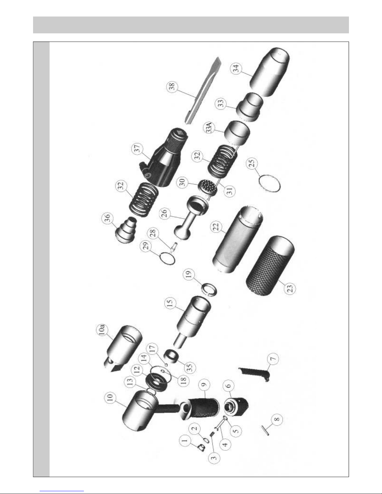
EXPLODED VIEW
EXPLODED VIEW

ITEM
No.
PART No. DESCRIPTION ITEM
No.
PART No. DESCRIPTION
Common Parts Common Parts
1 615 3021 Valve Cap 28 636 3003 Valve Pin
2 809 0139 Valve Cap O’Ring 38 704 3101 Chisel 1/2” Sq Shank 7” x 3/4” Blade
3 712 3022 Valve Spring 704 3103 Chisel 1/2” Sq Shank 7” x 2 1/2” Blade
4 618 3022 Valve Stem 704 3205 Chisel 1/2” Sq Shank 7” x 1 3/8” Blade
5 809 0089 Valve Seat O’Ring 704 3110 Chisel 1/2” Sq Shank Spark Resistant 2” Blade
6 616 3021 Valve Body 705 1102 Chisel 5/8” Hex Shank 8” x 4” Blade
423 3021 Valve Body Assembly (includes items 1-8) 705 1106 Chisel 5/8” Hex Shank 9” x 2” Blade
7 716 3000 Throttle Lever 705 1112 Chisel 5/8” Hex Shank Spark Resistant 4” Blade
8 813 0108 Roll Pin 708 1100 Comb Holder 5/8” Hex Shank (for 1 1/2” Comb)
9 717 3050 Rubber Handle Grip 431 3504 Scraper 5/8” Hex Shank c/w 4” Blade
17 816 3003 Plastic Ball 6mm diameter
18 809 0080 Ball Retaining O’Ring 819 2375 Connector 1/4” BSP-3/8” Stem
VL203/223 Components VL303 Components
10 425 2003 VL203 Cover Assembly (Pistol Grip) 10 425 3003 Cover Assembly (Pistol Grip)
10a 616 2003 VL223 Cover Assembly (Inline) 12 652 3003 Guide Plate
12 652 2003 Guide Plate 13 829 3003 Guide Plate Seal
13 829 2003 Guide Plate Seal 14 809 0299 Guide Plate O’Ring
14 809 0299 Guide Plate O’Ring 15 428 3003 Cylinder
15 428 2003 Cylinder 19 809 3004 Piston Cushion
19 809 2004 Piston Cushion 22 622 3031 Intermediate Tube
22 622 2031 Intermediate Tube 23 721 3003 Intermediate Tube Outer Sleeve
23 721 2003 Intermediate Tube Outer Sleeve 24 814 3003 Circlip VL303 only
25 809 0299 Front Tube Locking O’Ring 25 809 0299 Front Tube Locking O’Ring
26 612 2003 Piston 26 612 3003 Piston
29 829 2002 Piston Ring 29 829 3002 Piston Ring
30 601 2030 3mm Needle Holder (fitted as standard) 30 601 3030 3mm Needle Holder (fitted as standard)
601 2020 2mm Needle Holder 601 3020 2mm Needle Holder
31 413 2119 Needle 3mm Chisel set (fitted as standard) 601 3040 4mm Needle Holder
412 1151 Needle 2mm Flat set 31 413 2128 Needle 3mm Chisel set (fitted as standard)
413 1119 Needle 3mm Flat set 412 1165 Needle 2mm Flat set
413 3119 Needle 3mm Pointed set 413 1128 Needle 3mm Flat set
403 1309 Needle set (1 x set Beryllium Copper) 413 3128 Needle 3mm Pointed set
32 712 2003 Front Spring 403 1328 Needle set (1 x set Beryllium Copper)
33 620 2003 Front Tube Insert 413 3128 Needle 4mm Flat Tipped
33A 620 2003A Front Tube Spacer 32 712 3003 Front Spring
34 622 2030 Front Tube 33 620 3003 Front Tube Insert
35 809 3005 Cylinder Stem Reaction Ring 34 622 3030 Front Tube
36 610 2003 Anvil 35 729 3003 Cylinder Stem Reaction Ring
37 419 2003 Chisel Holder 36 610 3003 Anvil
37 419 3003 Chisel Holder
446 2003 Service Kit, (2, 5,13,14,17,18,19,28,29,30,31set & 32) 446 3003 Service kit, (2,5,13,14,17,18,19,28,29,30,31set & 32)
PARTS LIST

TECHNICAL SPECIFICATION
Mach nery D rect ve Informat on:
This tool has been designed and produced in accordance with the following directives: 2006/42/EC Machinery Directive
If your company has any problem with our products or would like to discuss the possibility of an improvement being made to them, then please do not
hesitate to contact us Your comments are both important and appreciated
Trelawny tools are thoroughly tested under specified conditions in accordance with applicable internationally recognised standards When a tool is
used on site the conditions may not be the same as those used in our tests
Trelawny Surface Preparation Technology operates a policy of continuous product development and refinement and therefore reserves the right to
change technical specifications and product designs without giving prior notice
© Copyright 2009, Trelawny SPT Limited, CV31 1XT UK All rights reserved Any unauthorised use or copying of the contents or part thereof is
prohibited This applies to trademarks, model denominations, part numbers and drawings Use only genuine Trelawny spares
The use of non-Trelawny spare parts nval dates the warranty.
Trelawny SPT Limited
Trelawny House, 13 Highdown Road, Sydenham Industrial Estate,
Leamington Spa, Warwickshire, CV31 1XT, United Kingdom
Telephone: +44 (0)1926 883781 Fax: +44 (0)1926 450352 Email: sales@trelawny co uk
General Industry Website: www trelawnyspt com
Dedicated Marine Website: www trelawny-marine com
© TSPT UK 2009 Part No: 735 3003 issue 7
SURFACE PREPARATION TECHNOLOGY
VL223 INLINE
NEEDLE
VL223 INLINE
CHISEL
VL203 PISTOL
GRIP NEEDLE
VL203 PISTOL
GRIP CHISEL
VL303 PISTOL
GRIP NEEDLE
VL303 PISTOL
GRIP CHISEL
P ston D ameter 23 5mm (0 925”) 23 5mm (0 925”) 23 5mm (0 925”) 23 5mm (0 925”) 34 4mm (1 35”) 34 4mm (1 35”)
P ston Stroke (approx mate) 11mm (0 43”) 11mm (0 43”) 11mm (0 43”) 11mm (0 43”) 20mm ( 787”) 20mm ( 787”)
BPM 2400 2400 2400 2400 3000 3000
A r Consumpt on @ 6.2bar 1 89lps (4 0cfm) 1 89lps (4 0cfm) 1 89lps (4 0cfm) 1 89lps (4 0cfm) 2 6lps (5 5cfm) 2 6lps (5 5cfm)
Overall Length 370mm (14 5”) 435mm (17 1”) 340mm (13 38”) 395mm (15 5”) 370mm (14 6”) 300mm (11 8”)
We ght 2 35kg (5 18lbs) 2 95kg (6 5lbs) 2 70kg (6 0lbs) 3 2kg (7 05lbs) 3 51kg (7 74lbs) 4 25kg (9 36lbs)
Needle/Ch sel 51 x 2mm
19 x 3mm
19mm (3/4”)
Fitted as
standard
19 x 3mm
51 x 2mm
19mm (3/4”)
Fitted as
standard
65 x 2mm
28 x 3mm
19 x 4mm
19mm (3/4”)
Fitted as
standard
No se LwA (Power Level) 90 7 db(A) 76 3 db(A) 90 7 db(A) 76 3 db(A) 109 5 db(A) 78 2 db(A)
V brat on (AEQ) Pr mary 2 56 m/s
2
(k) 3 69 m/s
2
(k) 2 75 m/s
2
(k) 3 33 m/s
2
(k) 2 3 m/s
2
(k) 3 7 m/s
2
(k)
V brat on (AEQ) Secondary 2 95 m/s
2
(k) 3 59 m/s
2
(k) 3 26 m/s
2
(k) 4 14 m/s
2
(k) 3 7 m/s
2
(k) 4 3 m/s
2
(k)
No se Levels
Noise level measured in accordance with: EN ISO 15744: 1999
V brat on Levels
Vibration measured in accordance with: EN ISO 28927 and EN ISO 20643
(k) Equals the factor of uncertainty, which allows for variations in measurement and production Vibration Data figures are tri-axial, which gives the total vibration emission
Because of various factors, the range of vibration from these tools may vary between -0% +40% The vibration is dependent on the task, the operators grip and feed force
employed etc
NOTE: The above vibration levels were obtained from tri-axial measurements to comply with the requirements of “The Control of Vibration at Work Regulations 2005*” and
the revisions to the (8662) now EN ISO 28927 and EN ISO 20643 series of standards These values are at least 1 4 times larger than the values obtained from single axis
measurements
*Based on European Union Council Directive 2002/44/EC (Physical Agents (Vibration) Directive)
R sk of Hand Arm Injury
Because of various factors, the vibration from this range of tools may be between 2 3 m/s2 – 6m/s2
The vibration is dependent on the task, the operators grip, and feed force employed
This manual suits for next models
2
Table of contents
Other Trelawny Media Converter manuals


Popular Media Converter manuals by other brands


Siemens
Siemens 7XV5652-0xA00 Series operating instructions

Cross Technologies
Cross Technologies 2017-14 instruction manual

Dolby Laboratories
Dolby Laboratories Vision CMU user manual

D-Link
D-Link DEM-310GT Features guide

Link electronics
Link electronics Caption Encoder/Decoder SD SDI/Analog... Specifications

M2TECH
M2TECH Vaughan user manual