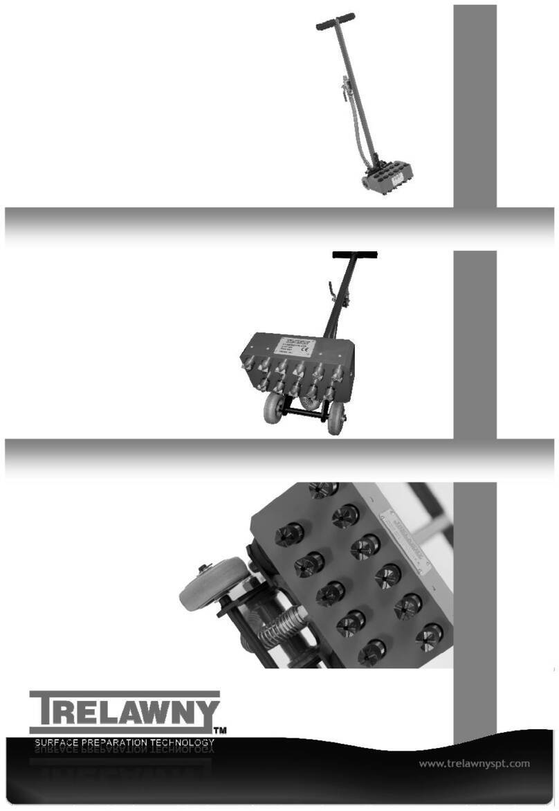
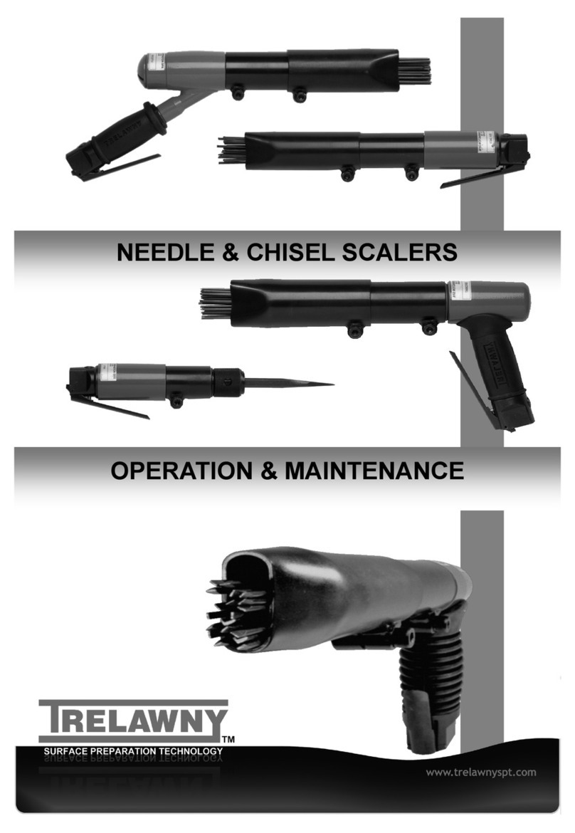
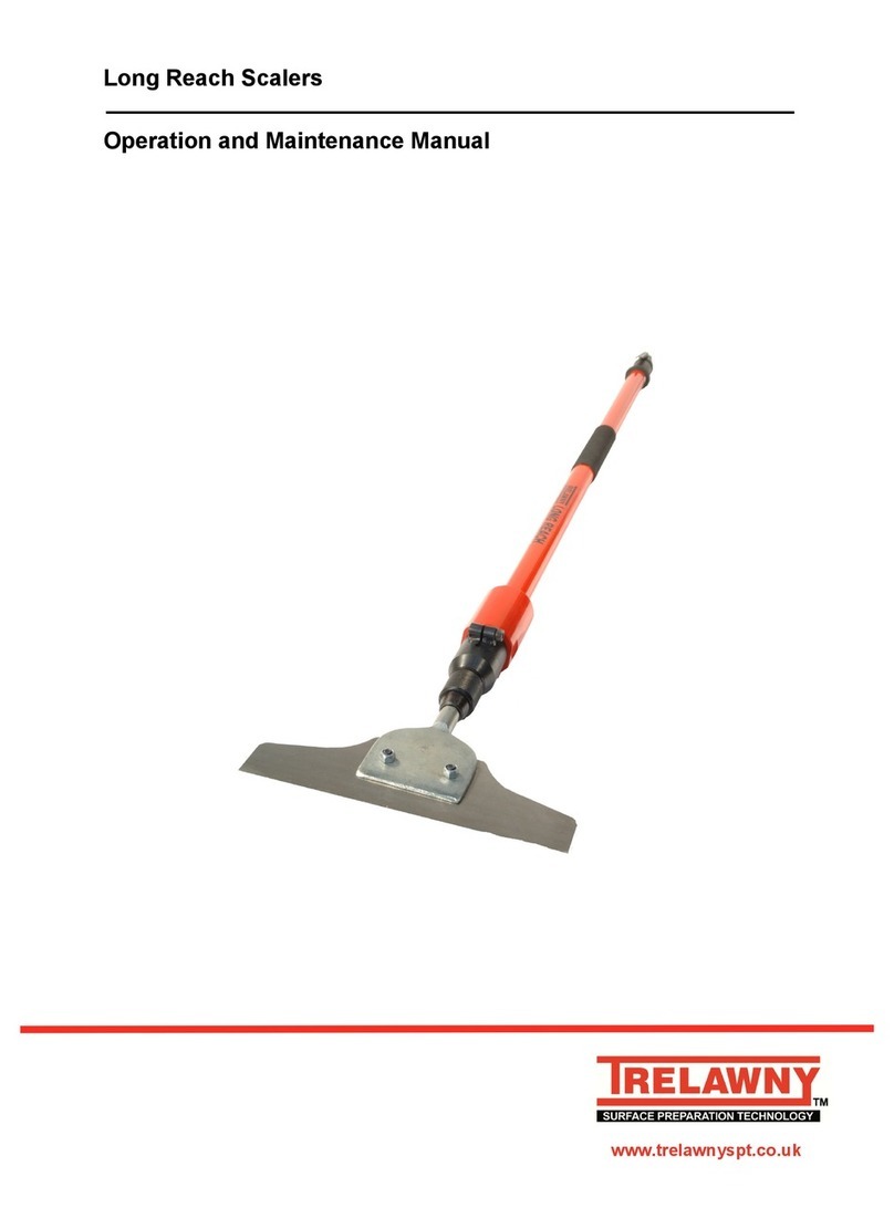
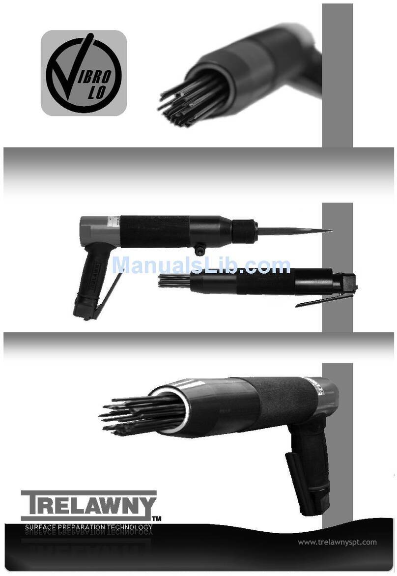
Trelawny VL303Ex User manual

www.trelawny.co.ukwww.trelawny.co.uk
VL303ex chisel SCALER
operations and maintenance manual

PAGE 2
VL303EX Chisel Scaler
CONTENTS
Introduction ................................................................................................................................................................ 2
Declaration of Conformity..................................................................................................................................... 3
Foreword ...................................................................................................................................................................... 6
General Information ................................................................................................................................................ 6
Safety ............................................................................................................................................................................. 6
Risk of Hand Arm Vibration .................................................................................................................................. 7
Air Supply ..................................................................................................................................................................... 7
Starting Work ............................................................................................................................................................. 7
Maintenance ............................................................................................................................................................... 8
Assembly ...................................................................................................................................................................... 9
Disposal ........................................................................................................................................................................ 9
Exploded ...................................................................................................................................................................... 10
Parts List ....................................................................................................................................................................... 11
Technical Specication........................................................................................................................................... 12
INTRODUCTION
Your new Trelawny SPT tool will more than satisfy your expectations. It has been manufactured under stringent
Trelawny SPT Quality Standards to meet superior performance criteria. You will nd your new tool easy and safe to
operate, and, with proper care, it will give you many years of dependable service.
WARNING
Carefully read through these original instructions before using your new Trelawny tool. Take special
care to read the warnings. Your Trelawny tool has many features that will make your job faster and
easier. Safety, performance, and dependability have been given top priority in the development of
this tool, making it easy to maintain and operate.
ENVIRONMENTAL PROTECTION
The machine, accessories and packaging should be sorted for environmentally friendly
recycling. The plastic components are labelled for categorised recycling.
DISPOSAL
Waste products should not be disposed of with household waste. Please recycle where
facilities exist. Check with your local authority or retailer for recycling advice.

www.trelawny.co.uk
DECLARATION OF CONFORMITY
Adam Dickinson,
Managing Director
We,
Trelawny SPT Limited of
Trelawny House, 13 Highdown Road, Sydenham Industrial Estate, Leamington Spa, Warwickshire, CV31
1XT, United Kingdom,
Declare that under our sole responsibility for supply/manufacture of the product
Name of product Chisel Scaler
Model VL303Ex
to which this document relates is in conformity with the provisions of the following Directive(s),
Normative Documents and their relevant Standards:
2006/42/EC MACHINERY DIRECTIVE
EN ISO 11148-4:2010 HAND HELD NON-ELECTRIC
(Non-Rotary Percussive Tools)
EN ISO 4414:2010 General rules and safety requirements
EN ISO 4414 SAFE PNEUMATIC EQUIPMENT OF MACHINERY
Conformity with the following relevant legislation:
2014/34/EU ATEX DIRECTIVE
Based on following harmonised standards:
EN 60079-0:2018
EN ISO 80079-36:2016
EN ISO 80079-37
II 2 G Ex h IIC T4 Gb
II 2 D Ex h IIIC T135°C Db
www.trelawny.co.uk
Email: sales@trelawny.co.uk
Tel: +44 (0) 1926 883781
Fax: +44 (0) 1926 450352
Year and place of issue,
2020
Leamington Spa, England
________________________
Registered Oce: Trelawny SPT Ltd, Trelawny House, 13 Highdown Road, Sydenham Industrial Estate, Leamington Spa, Warwickshire, CV31 1XT, United Kingdom
DOCUMENT No. Q:57/8
________________________________________________________________________________________________________

PAGE 4
VL303EX Chisel Scaler
CZ Prohlášenl o přizpüsobení
My, společnost Trelawny SPT Limited
podajemy daňové přiznáni. že výrobek a dodávka výrobku
název výrobku
Model, výrobni čislo
Rok výroby
Pro které se průkaz týkajici, je přizpůsobeni s zásoby od následujici přikazov a jejich pohotovostni:
98/37/EC Přikaz soustroji
73/23/EC Přikaz nizkého napéti (upotřebitelne jediné do výrobku použiti elektnckej energie)
LT ATITIKTIES DEKLARACIJA’
Mes, Trelawny SPT Limite
Prisiimdami visą atsakomybę deklaruojame, kad tiekiamas / gaminamas produktas
Produkto pavadinimas
Modelis, serijos numeris
Pagaminimo
Kuriam taikoma ši deklaracija, atitinka šių direktyvų, norminių aktų ir su jais susijusių. standartų reikalavimus:
98/37/EC ļtrangos direktyva
73/23/EC Zemos įtampos direktyva (taikoma tik elektriniams įrengimams)
DE Ubereinstimmungserklarung
Wir, Trelawny SPT Limited
erklaren, dass unter unserer alleinigen Verantwortung fur die Lieferung und Herstellung des Produktes
Name des Produktes
Model, Seriennummer
Jahr der Herstellung
auf welches sich dieses Dokument bezieht. stimmt mit den Vorgaben der folgenden Direktive, normativen Dokumente und deren
jeweiligen Masstabe ein:
98/71/EC Maschineriedirektive
73/23/EC Niederspannungsdirektive (nur zutreffend auf Produkte, die Strom benutzen)
MT DIKJARAZZJONI TA KONFORMITA
Aħna, Trelawny SPT Limited
Niddikjaraw li aħna responsabbli kompletament għal provista / manifattura tal-prodott hawn 1msemmi:
lsem ll-Prodott
Mudell, Serial number
Sena Ia 'produzzjoni
Dan id-dokument magħmul għal prodott imsemmi hawn fuq, li huwa skond il-provizjonijiet imsemmija d-dokumenti tal-klassi tax-
xogħol:
98/37/EC Machinery Directive
73/23/EC Low Voltage Directive (tapplika biss għal prodotti li jaħdmu bl-eletrkiu)
DK Erklæring om overensstemmelse
Vi, Trelawny SPT Limited
Erklærer hermed at under vores ene forhandling ansvar for vores forhandling/produktion af produktet
Produkt navn
Model, serie nummer
Produktionsár
For hvilket delle dokument referer, at deler i overensstemmelse med bestemmelser af følgende direktiver, normative dokumenter
og deres relevante standart:
98/37/EC Machinery directive
73/23/EC Low voltage directive
NL EENVORMIGHEIDSVERKLARING
Wij. Trelawny SPT Limited
Verklaren dat wij de volledige verantwoordelijkheid dragen voor het leveren/fabriceren van het volgende product:
Naam van het product
Type, Serienummer
Productiejaar
En verklaren dat het product waarnaar dit document verwijst eenvormig is met de voorzieningen van de volgende Richtlijn(en),
Normatieve Documenten en hun relevante Standaarden:
98/37/CE MACHINERICHTLIJN
73/23/CE LAAGSPANNINGSRICHTLIJN (uitsluitend van toepassing bij producten die elektrische stroom gebruiken)
EE TOOTE VASTAVUSE DEKLARATSIOON
Meie, Trelawny SPT Limited
Deklareerime, et vastutame jägmise varustuse/toote müügi eest
Toote nimetus
Mudel, Seeria number
Aasta toodangu
Antud dokument töendab toote vastavust järgmistele direktiivi(de)le, normatiivaktidele ja nendega samaväärsetele standarditele:
98/37/EC MASINA DIREKTIIVID
73/23/EC MADALPINGE DIREKTIIVID (Kohandatakse vaid toodetele, mis kasutavad elektrivoolu
PL Deklaracja Zgodnosci
My, Firma Trelawny SPT Limited.
oświadczamy w naszej odpowiedzialności, ze produkcja i dostawa urzctdzenia
Nazwa produkta
Model, numer seryjny
Rok produkcji
do którego ten dokument należy, jest zgodne z klauzulami nastąpujacych zarządzen i ich istotnych standartów:
98/37/EC Zarządzenie mechaniczne
73/23/EC Zarządzenie niskiego napięcia elektrycznego (Zastosowanie tylko przy urządzeniach elektrycznoych)
ES Declaración de Conformidad
Nosotros, Trelawny SPT Limited
Declaramos que bajo nuestra completa responsabilidad de Ia fabricación/suministro del producto
Nombre del Producto
Modelo, No de Serie
Año de producción
A quién este documento se refiere, está de acuerdo con lo relacionado en Ia Directriz, Normativa Documentada y sus relevantes
standards:
98/37/EC Directorio de Maquinaria
73/23/EC Directorio de Bajo Voltaje (Aplicable solamente a productos que funcionen con electricidad)
PT DECLARAÇÄO DE CONFORMIDADE CE
A empresa TRELAWNY SPT LIMITED
Declara, sob sua inteira responsabilidade, que o fornecimento/fabrico do seguinte produto:
Designaçáo do produto
Modelo, Nümero de Série
Ano de produçáo
a que esta declaraçáo se refere. está em conformidade com o preceituado nas Directivas e Normas Comunitárias abaixo indicadas:
98/37/EC DIRECTIVA DE MÁQUINAS
73/23/EC DIRECTIVA DE BAIXA VOLTAGEM (Aplicável apenas a produtos que utilzi am energia eléctrica)
FI ILMOITUSVAHVISTUS
Me. Trelawny SPT Limited
Vahvistamme tuotteiden toimittamisesta/valmistamisesta
Tuotenimi
Malli, sarjanumero
Valmisttusvuosi
Tällä todistuksella vahvistamme säädökset seuraviin ohje/ohjesiin, Yleisiin papereihin ja niihin liittyvät vaatimukset:
98/37/EC KONEISTON OHJEET
73/23/EC PIENJÄNNITE OHJEET (tarvitaan ainoastaan tuotteille jotka käyttävät sähkovoimaa)
RU CBИдETEПЬCTBO O COOTBETCTBИИ
Mьι, Trelawny SPT Limited
3aявляем, что несем полную ответственость эа поставκу/производство нижеукаэанной
продуκцим
Hаименоване изделия
Mодель, серийньιй номер
Год вьιлуска
на котоеую вьιдано настящее Cвидетельство, и которая соответствует положениям слдующей(иx) директив(ьι),
нормативньιм доκументам и относящимся к ним стандартам:
98/37/EC ДИРЕКТИВА ПО MEXAHИ3MAM
73/23/EC ДИРЕКТИВА ПО HИ3KOBOЛЬTHOMУ OЪOPУДOBAHИЮ (распространяется только на изделия с
злектропитанием)
FR DÉCLARATION DE CONFORMITÉ
Nous, soussignés Trelawny SPT Limited
déclarons que le produit sous-nommé
Nom du produit
Modèle et Numéro de Serié
Année de production
et pour lequelnous prenons entière responsabilité pour sa fourniture et manufacture, est conforme aux clauses des directives
suivantes documents norminatifs et normes qui s'y appliquent:
98/37/EC DIRECTIVE POUR LA MACHINERIE
73/23/EC DIRECTIVE POUR BAS VOLTAGE (n'est applicable qu'aux produits utilisant l'énergie électrique)
SE FÖRSÄKRAN OM ÖVERENSSTÄMMELSE
VI, TRELAWNY SPT LIMITED
FÖRKLARAR ATT VI MED ENSAMT ANSVAR ANSKAFFAT / TILLVERKAT PRODUKTEN PRODUKTNAMN
MODELL och SERlE NUMMER
Tillverkningsár
TILL VILKEN DETTA DOKUMENT HÄNVISAR ÄR I ÖVERENSSTÄMMELSE MED FÖLJANDE DIREKTIV, NORMATIVA
DOKUMENT OCH DERAS RELEVANTA STANDARDER
98/37/EC MASKINDIREKTIV
73/23/EC LÄGSTRÖMSDIREKTIV (TILLÄMPLIG PÄ ELEKTRISK DRIVNA PRODUKTER)
GR ΔΗΛΩΣΗ ΠΙΣΤΟΤΗΤΑΣ
Η εταιρεια Trelawny Spt Limited
Δηλωνει ότι έχει τη μονδικη ευθυνη ως κατασκευαστρια / προμηθευτρια του παρακατω προιοντος περιγραφη προιοντος
μοντελο, αριθμος σειρας
έτος παραγωγής
και στο οποιο αναφερεται αυτη η δηλωση, ειναι συμβατο με τις προδιαγαφες που οριϚονται στιϚ ακολουθεϚ Koινοτικες
OδηγιεϚ EλεγκτικεϚ ΔιαταξειϚ κι αλλεϚ σχετικες προδιαγραφεϚ
98/37/EC OΔHΓΙΑ ΠΕΡΙ ΜΗΧANHMATΩN
73/23/EC OΔHΓΙΑ ΠΕΡΙ XAMHΛHΣ TAΣHΣ (αφορα μονον προιοντα που λειτουργουν με ηλεκτρικο ρευμα)
SI IZJAVA O SKLADNOSTI
Trelawny SPT Limited
pod polno odgovornostjo izjavljamo, da so spodaj navedeni proizvodi, ki jih dobavljamolproizvajamo:
lme proizvoda
Model. serijska številka
Leto proizvodnje
na katere se ta dokument nanaša. proizvedeni v skladu z določili naslednjih direktiv, normativnih dokumentov in njihovih relevant-
nih standardov:
98/37/EC DIREKTIVA O STROJIH
73/23/EC DIREKTIVA O STROJIH Z NIZKO VOLTAŽO (nanaša se samo na proizvode na električni pogon)
HU MEGFELELŐSÉGI NYILATKOZAT
Mi. A "Trelawny SPT Limited" cég
Felelösségünk tudatában kijelentjük, hogy mint a termék szállitója/gyartója
Termék neve
Tipus, Sorozatszáma
Gyártási év
amelyre jelen dokumentum vonatkozik, megfelel az alábbi lrányelv(ek), lrányadó Dokumentumok elöirásainak, és az azokat
meghatározó szabvanyoknak:
98/37/EC GÉPÉSZETI IRÁNYELVEK
73/23/EC KISFESZÜLTSÉGÜ IRÁNYELVEK (Csak az elektromos meghajtásů gepeknél)
TR UYGUNLUK BEYANI
Trelawny SPT Limited
AÞaöýdaki, üretim ve tedarikinden tek baÞýna sorumlu olduöu ürünün
Ürün ady
Modei/Seri no
Üretim yili
bu belgenin ilgili olduöu apaöýdaki yönetmeliklerin, norm belgelerinin ve ilgili standartlarýnýn koÞullarýna uygun olduöunu beyan
eder:
98/37/EC MAKŶNALAR YÖNETMELŶDŶ
73/23/EC DÜÞÜK GERŶLŶM YÖNETMELŶDŶ (Yalnýýz elektrikle çalyÞan ürünlerde geçerlidir)
IT DICHIARAZIONE Dl CONFORMITA
La Società Trelawny SPT Limited
Dichiara, sotto Ia propria responsabilità, che Ia fornitura / produzione del prodotto
Nome prodotto
Modello, codice
Anno di produzione
a cui si riferisce tale documento è conforme aile seguenti Direttive, ai documenti della Normativa ed ai relativi standard:
98/37/EC DIRETTIVA SULLE APPARECCHIATURE
73/23/EC DIRETTIVA SUL BASSO VOLTAGGIO (applicabile esclusivamente peri prodotti che utilizzano energia elettrica)
DECLARATION OF CONFORMITY

www.trelawny.co.uk
DECLARATION OF CONFORMITY
Appendix 1 - Hazardous Area Certication
The VL303Ex Chisel Scalers are certied compliant to the ATEX Directive (2014/34/EU) for safe use
within a hazardous area and has been assessed so by Element Materials Technology.
This product conforms to the Standards:
EN 60079-0:2018
EN ISO 80079-36:2016
EN ISO 80079-37
And is attributed with the product certication codes:
II 2 G Ex h IIC T4 Gb
II 2 D Ex h IIIC T135°C Db
With ATEX Certicate Number: EMT19ATEX0022X
Special Conditions of Safe Use
1. Air compressors used in conjunction with the Scaling Hammers shall incorporate means to prevent
the ingress of dust or other foreign material into the air supply i.e a lter on the compressor intake.
2. For air compressors used in conjunction with the Scaling Hammers, only lubricants that are resistant
to carbonisation shall be used.
3. The external painted surfaces of the equipment are not to be exposed to charging mechanisms
stronger than manual rubbing.
4. Air supply hoses used in conjunction with the equipment must be manufactured from anti-static
material with a surface resistance no greater than 10°Ω.
5. Equipment is to be lubricated before as detailed in the Operations & Maintenance Manual.
6. Any lubricating oil used must have an auto ignition temperature of > 185°c.
7. The equipment must not be stored in an explosive acetylene atmosphere (to prevent the formation of
acetylides on the copper heads).
Equipment must only be installed & maintained by suitably qualied and competent personnel in
accordance with the instructions provided and the terms of the applicable product services.

PAGE 6
VL303EX Chisel Scaler
FOREWORD
GENERAL INFORMation
Thank you for your purchase of the VL303EX Chisel Scaler.
This manual contains the necessary maintenance information
for you to ensure proper operation and care for this machine.
It is essential for you to read through this manual thoroughly.
In the unlikely event that you experience problems with your
VL303EX Chisel Scaler, please do not hesitate to contact your
local Trelawny dealer or agent. We always welcome feedback
and comments from our valued customers.
Before operating, performing maintenance or repairing
the VL303Ex Chisel Scalers, this manual must be read and
understood. If in any doubt, ask your supervisor before using
this equipment.
Local safety regulations must be followed at all times. Failure
to follow these instructions could result in damage to the
Scaler and/or personal injury. Operators should be familiar
with the data given in the specication section. Please keep
these instructions in a safe and accessible place.
Trelawny SPT Limited disclaims all responsibility for damage
to persons or objects arising as a consequence of incorrect
handling of the tool, failure to inspect the tool for damage or
other faults that may inuence the operation prior to starting
work, or failure to follow the safety regulations listed or
applicable to the job site. The tool is primarily designed for the
removal of paint, rust, scale, and for the removal of laitance
from concrete, it can be used both indoors and out. This tool
must not be used in a xture.
WARNING! Before operating, performing maintenance
or repairing the VL303Ex this manual must be read and
understood. If in any doubt, ask your supervisor before
using this equipment.
SAFETY
Do:
- Be aware that this tool is not electrically insulated.
- Be aware that the tool can create dust and ying debris.
- Keep hands and clothing away from moving parts.
- Be aware of others working around you.
- Ensure that this tool is lubricated daily.
- Store this tool in a secure and dry environment.
- Wear Personal Protective Equipment including safety
goggles, footwear, ear defenders and gloves. In some
environments it will be necessary to wear facemasks or
breathing apparatus.
- Always observe safe-working practices at all times.
Do not:
- Allow the tool to run unattended.
- Use the scaler as a lever.
- Modify this tool in any way, this will invalidate the warranty
and could also lead to serious injury.
- Use wire or any other xing to lock the throttle lever in the
on/open position.
- Drag the tool by the air hose.
- Use petrol (gasoline), thinners or any other high ash point
solvent to clean the tool.
- Use the tool if you become tired, this can lead to physical
strain or injuries; where practical; use a spring balance,
balance weights or similar equipment to take the weight of
the tool.
- Hold the exposed chisel, whilst the tool is in use, this could
cause vibration damage to the hands.
Please note: Unrestrained hoses can whip if they become
detached. Care must be taken to avoid damaging or tripping
over the trailing air hose.
WARNING! Always observe safe-working practices at
all times.

www.trelawny.co.uk
RISK OF HAND-ARM VIBRATION INJURY
air supply
STARTING WORK
These tools may cause Hand-arm Vibration Syndrome injury
if their use is not adequately managed. We advise you to
carry out a risk assessment and to implement measures
such as; limiting exposure time [i.e. actual trigger time, not
total time at work], job rotation, ensuring the tools are used
correctly, ensuring the tools are maintained according to
our recommendations, and ensuring that the operators wear
personal protective equipment [PPE] particularly gloves and
clothing to keep them warm. Employers should consider
setting up a programme of health surveillance to establish
a benchmark for each operator and to detect any early
symptoms of vibration injury.
We are not aware of any PPE that provides protection
against vibration injury by attenuating vibration emissions.
See ‘Specications’ section for vibration emission data.
We strongly advise you to visit the Health & Safety
Executive website http://www.hse.gov.uk/vibration
This site provides excellent advice and information on HAV
and currently, includes a Hand-arm Vibration Exposure
Calculator that is easy to use to work out the daily vibration
exposure for each of your operators.
The compressed air must be free from water and dirt.
The installation of a lter/regulator/lubricator air
preparation set (with moisture trap) adjacent to the tool
is strongly recommended.
In particularly cold temperatures it is recommended that a
proprietary anti-freeze lubricating oil is used. Always clear
the air hose before connection to the tool. Ensure that no
moisture (condensation) is present in the air hose. Ensure that
only 10mm (3/8”) bore antistatic air hose is used and that all
couplings are secure, leak free and in good condition.
For maximum eciency, limit the length of air hose to 10M
(33ft). Where extra length is necessary, for each additional
15M (50ft) of air hose used, the pressure drop is approximately
0.16bar (3psi). The correct air pressure for this machine is to
6.2bar (90psi).
Do not let the operating pressure fall below 5.5bar (80psi) or
rise above 6.9bar (100psi) absolute maximum. The compressor
should be able to supply a minimum of 3.77 L/s (8cfm)
of free air not displaced as quoted by some compressor
manufactures, this will give 3cfm of headroom,
so that the compressor isn’t continually running.
NOTE: If this tool stops working, it is most likely that the plastic
(17) ball has worn excessively and may have passed into the
cylinder, check the cylinder exhaust holes for the remnant
also. This is designed to run for approximately 160hrs before
requiring replacement.
Please note we recommend using a lanyard or strap attached
to the optional Drop Protection fall arrestor (39). This should
be attached to a belt or harness, but preferably to a xed and
secure mounting point.
Always use Trelawny Aluminium Bronze Chisels.
Prior to operating the tool check: -
That all ttings are secure, free from leaks and air hoses are in
good condition.
That the air pressure is correct for this tool 6.2 bar (90 p.s.i.).
Put a few drops of a recommended lubricant into the air inlet
of the tool.
Safe use of this tool requires a solid stance and secure
foothold, the tool may be used in other postures but care must
be taken that the operator adopts a rm and stable position.
Maintain contact with the work surface with sucient pressure
only to keep the tool from bouncing.
Excessive pressure can prevent the tool from working to its full
capacity.
Handled correctly the VL303Ex Chisel Scaler will work quickly
and eciently. Excessive operator pressure will not improve
the tool eciency but could cause premature tool failure and
operator fatigue.
Never allow the tool to run continuously whilst not in contact
with the surface being prepared.
To operate the tool, pull the throttle lever (7) towards the
handle and then apply the chisel to the surface to be worked.
To switch o, simply release the throttle lever.
Gloves and personal protective equipment must be worn
when using this tool.
WARNING! VERY IMPORTANT
Only Trelawny Aluminium Bronze Chisels must be used
in this tool.
DO NOT substitute with any other Chisel.

PAGE 8
VL303EX Chisel Scaler
MAINTENANCE
Maintenance must only be carried out by a competent
person, in a suitably equipped workshop.
Disconnect the tool from the air supply before carrying out
any of the following operations.
Clean all debris from the exterior of the tool.
This tool has been designed so that you only require a
vice, screwdriver, 3mm pin punch, 6mm allen key and light
hammer, no other specialist tools are required to completely
strip and service the tool.
For safe ecient running and at intervals of no more than 120
hours, dismantle and clean with highly rened paran.
Check all components for wear, replace the 6mm Ball (Item
17) and all O’Rings. Immediately after cleaning, thoroughly oil
the tool with one of the recommended lubricants.
Recommended lubricants
Oil the tool daily during use. Put a few drops of one of the
following bio-degradable air tool lubricants through the air
inlet.
SHELL Naturelle HF
CASTROL Carelube HTG 22
Always use clean oil from a sealed container and ensure
ignition temperature is above 185deg C.
Tool Dismantling
Before carrying out any dismantling, ensure the air supply
is turned o and remove the air-line from the tool. Clean all
deposits from the outside of the tool. Service kits are available,
see parts section.
Chisel Holder removal
Hold the Cover in a vice using the ats provided, keeping the
Chisel holder (37) vertical. Loosen Pinch bolt & Unscrew Anti
Clockwise by hand, remove the Chisel holder (37) complete
with the Spring (32) as an assembly.
Piston and Cylinder removal
Hold the Cover in a vice using the ats provided, keeping the
Chisel holder (37) vertical. Loosen Pinch bolt & Unscrew Anti
Clockwise by hand, remove the Chisel holder (37) complete
with the Spring (32) as an assembly.
Note: When removing tool from vice, do not point the front of
the tool downward; the piston may fall out of the Intermediate
Tube causing damage.
Hold a clean lint free cloth over the open end of the
Intermediate Tube, remove from vice and tilt the Tube
downwards to remove the Piston (26). Secure the Cover (10) in
a vice with the Intermediate Tube in the vertical position, using
the ats provided.
Use a suitable 6mm bar through the holes provided, unscrew
the Intermediate Tube (22) anticlockwise. Carefully remove the
Intermediate Tube from the cover and remove the Cylinder
from its location hole in the Cylinder Guide Plate, which is
tted in the cover.
The Cylinder Guide Plate (12) can be pulled out of the cover to
gain access to the Guide Plate Seal (13).
Cylinder Ball Valve replacement
This is a consumable item and will require replacing after
approximately 120 -160 hours use; this is dependant on the
cleanliness of the air supply and frequency of lubrication.
Do not replace this plastic ball with a steel version, as it will
damage the cylinder valve seat and piston valve pin.
The ATEX certication will also become invalid.
Remove the ball retaining O’Ring (18) from its groove
just inside the bore of the stem using a suitable pointed
implement. Remove the ball from the bore or if it has worn
excessively and may have passed into the cylinder, check the
cylinder exhaust holes for the remnant also. Replace and ret
new O’Ring into groove.
Piston Valve Pin replacement
Hold the piston in a vice by the stem, using a pair of cutters
remove the top of the Valve Pin (28), using a drill & 6mm drill
bit and remove the remainder from the piston. A small socket
(4mm) which just ts over the actual pin, will stop damage
occurring. Drive the valve pin in up to its shoulder using a vice
or a small hammer.
Valve Body - Valve Stem removal
Hold the Valve Body (6) in a vice using the ats provided.
Using a 3 mm diameter punch, drive the Throttle Lever
retaining Spring Pin (8) out of the Valve Body (6) and withdraw
the Throttle Lever (7). Remove the Valve Cap with O’Ring (2),
Valve Spring (3), Valve Stem (4) and the Valve Seat O’Ring (5).
Valve Body removal
Remove the Chisel holder and Anvil and Return Spring as per
instructions. Replace the Chisel holder, onto the Intermediate
Tube and screw up until hand tight. Hold the Valve Body ats
securely in a vice, with the Cover (10) uppermost. Turn the tool
anti-clockwise around the Valve Body by holding the Cover
and Chisel holder, unscrew the Valve Body from the handle
until loose, remove from vice and nally unscrew by hand.
VERY IMPORTANT Before carrying out any dismantling,
ensuring the air supply is turned o,

www.trelawny.co.uk
ASSEMBLY
DISPOSAL
Ensure all parts are clean and internal parts have a lm
of recommended lubricant. Replace any parts that show
signs of wear. If the tool is being fully serviced, it is strongly
recommended to change all O’Rings (2), (5), (14), (18), (25), (27),
cushion ring (19), seals (13,) (29), ball valve (17).
Valve assembly
Replacement of the Valve Body onto the Cover assembly is
the reverse of removal. Use a few turns of P.T.F.E. tape on the
threads of the handle and screw on the Valve Body initially by
hand, then insert the Valve Body in a vice, holding securely on
the ats provided, and with the Cover (10) uppermost. Finally
tighten up clockwise by hand, holding the Chisel holder and
Cover, and align the Throttle Lever with the front of the tool
when resistance is felt. Replace the O’Ring (2) on the Valve
Cap (1). Fit a new Valve seat O’Ring (5) in the Valve Body (6).
Insert the Valve Stem (4), in the Valve Body (6). Place the Valve
Spring (3) on top of the Valve Stem (4),screw down the Valve
Cap (1) by hand, and then fasten until fully tight with a at
blade screwdriver. Locate Throttle Lever (7) in the Valve Body
(6) using a 3 mm punch to align holes. Secure by inserting
Spring Pin (8).
Tool assembly
Ensure that all components are clean and lubricated with
a thin lm of the recommended lubricating oil. Assembly is
the reverse of dismantling. Secure the Cover (10) vertically
in a vice using the ats provided, insert the Cylinder Guide
Plate ensuring that the at face is uppermost, ensure that it
is located onto the shoulder at the bottom of the threaded
section inside the Cover. Fit the Cylinder stem into the
bore of the Cylinder Guide Plate. With the removal holes
uppermost carefully slide the Intermediate Tube over the
Cylinder, screwing down by hand. Finally tighten by using a
6mm bar x 200mm through the holes provided. (Do not over
tighten). Gently insert the Piston, small diameter rst into the
Intermediate Tube, if resistance is felt, turn the piston slightly
until it is located in the cylinder.
Note: When removing tool from vice, do not point the front
of the tool downward; the piston will fall out of the tube and
become damaged. Remove the tool from the vice and follow
as per tting the Chisel holder, hold the tool horizontal when
completing this operation.
Fitting of Chisel Holder
The Chisel Holder assembly comprises of an Anvil, Spring,
Chisel Holder and the Chisel. To t the Chisel Holder, rst t
the spring onto the Anvil locating against the large shoulder.
Fit this assembly into the intermediate tube and locate the
large at face of the Anvil against the front face of the piston.
Ensure that the pinch bolt on the Chisel Holder is loose and
screw the Chisel Holder fully on to the intermediate tube.
Then unscrew slightly to position the boss underneath the tool
and tighten the pinch bolt using a 6mm AF Allen key. Turn the
knurled collar on the Chisel Holder until the retaining ball is
fully visible; insert the Chisel aligning the rebate with the ball.
Position the middle of the rebate on the shank of the Chisel
with the retaining ball and turn the collar half a turn to lock the
Chisel in place. To release the Chisel, rotate the knurled collar
until the retaining ball is fully visible and remove the Chisel.
Dismantle into component form, segregate according to
material composition and dispose of using waste recycling
processes specied by local regulations.
VERY IMPORTANT
Only Trelawny Aluminium Bronze Chisel must be used in
this tool.
DO NOT substitute with any other chisel.
WARNING! Maintenance must only be carried out by
a competent person, in a suitably equipped workshop.
Disconnect the tool from the air supply before carrying
out any of the following operations.

PAGE 10
VL303EX Chisel Scaler
EXPLODED DIAGRAM

www.trelawny.co.uk
Item NO. PART NO. DESCRIPTION
1615.3021 Valve Cap
2 809.0139 Valve Cap O’Ring
3 712.3022 Valve Spring
4 618.3022 Valve Stem
5 809.0089 Valve Seat O’Ring
6 423.3021 Valve Body Assembly BSP Thread
(inc items 1-8)
7 716.3000 Throttle Lever
8 813.0108 Roll Pin
9 717.3050 Rubber Handle Grip
10 425.3003 Cover Assembly (Pistol Grip)
12 652.3003 Guide Plate
13 829.3003 Guide Plate Seal
14 809.0299 Guide Plate O’Ring
15 428.3003 Cylinder
17 816.3005 Plastic Ball 6mm diameter
18 809.0080 Ball Retaining O’Ring
19 809.3004 Piston Cushion
22 622.3031 Intermediate Tube
23 721.3003 Intermediate Tube Outer Sleeve
24 814.3003 Circlip
25 809.0299 Front Tube Locking O’Ring
26 612.3003 Piston
28 636.3003 Valve Pin
29 829.3002 Piston Ring
32 712.3003 Front Spring
33 620.3003 Front Tube Insert
34 622.3030 Front Tube
35 729.3003 Cylinder Stem Reaction Ring
36 610.3003 Anvil
37 419.3003 Chisel Holder 1/2” square shank
38 704.3110 Chisel 1/2” Sq Shank Spark Resistant 2” Blade
39 512.3003 VL303 Drop Protection Kit Includes (40,41):
40 415:3003 Anti Static Lanyard
41 720.3003 VL303 Arrester Clamp Assembly
819.2375 Connector 1/4” BSPT-3/8” Stem
843.0825 1/4’’ BSP to NPT Connector
446.3303X Service Kit (2,3,4,7,8,13,14,17,18,19,25,28,32)
parts list

PAGE 12
VL303EX Chisel Scaler
Trouble Shooting Cause Action
Poor performance or lack of power.
Low air pressure. Ensure that the air pressure is correct at 90psi, max 100psi.
If tool has been left for some time without use, the oil may dry out
slightly, causing a sticky residue. Strip tool down, clean and re-oil.
Piston seal worn. Remove seal from piston and t into bore of cylinder. If it drops to the
bottom of the bore, a replacement is required.
Incorrect chisel tted. Ensure that the chisel is for a vibration reduced tool.
Valve pin broken. Replace valve pin and 6mm plastic ball.
Tool continues to run with trigger released. Valve seal may have become dislodged through the tool being
disconnected with the trigger in the open position.
Ensure that the trigger has not been taped or wired in the open
position, reposition or replace valve seat o’ring.
High vibration.
High air pressure. Ensure that the air pressure is correct at 90psi, max 100psi.
Lack of lubrication. Lubricate with the recommended air tool oil daily.
Low air pressure 70-80psi can also cause high vibration. Ensure that the air pressure is correct at 90psi, max 100psi.
Front return spring weak or broken. Replace return spring.
Guide plate seal worn. Replace guide plate seal.
Piston cushion failed. (This is a split o’ring) Replace with a new piston cushion.
Tool stopped working.
6mm plastic ball worn out. Check for and remove the remains of the ball, possibly in an exhaust
hole of cylinder and renew 6mm plastic ball.
Valve pin broken. Replace valve pin and 6mm plastic ball.
technical specication
Machinery Directive Information:
This tool has been designed and produced in accordance with the following directives: 2006/42/EC Machinery Directive
and applicable harmonised standard: EN ISO 1 1148-4:2012
EN ISO 11148-4: 2010 Hand Held Non-Electric (Non-Rotary
Percussive Tools)
This tool conforms with the following EC legislation: ATEX DIRECTIVE 2014/34/EU
Based on the following harmonised standards: EN60079-0:2018
EN ISO 80079-36:2016
EN ISO 80079-37
Notied Body: Element Material Technology LTD
Certicate Number: EMT19ATEX0022X
If your company has any problem with our products or would like to discuss the possibility of an improvement being made to them, then please do not hesitate to
contact us. Your comments are both important and appreciated.
Trelawny tools are thoroughly tested under specied conditions in accordance with applicable internationally recognised standards. When a tool is used on site the
conditions may not be the same as those used in our tests.
Trelawny Surface Preparation Technology operates a policy of continuous product development and renement and therefore reserves the right to change technical
specications and product designs without giving prior notice.
© Copyright 2015, Trelawny SPT Limited, CV31 1XT. UK All rights reserved. Any unauthorised use or copying of the contents or part thereof is prohibited. This applies
to trademarks, model denominations, part numbers and drawings. Use only genuine Trelawny spares.
The use of non-Trelawny spare parts will invalidate the ATEX certication and also the warranty.
Model Piston Diameter Piston Stroke
(approximate) BPM Air Consumption @
6.2bar Overall Length Weight Noise LwA (Power
Level)
Vibration (AEQ)
Primary
Vibration (AEQ)
Secondary
VL303Ex Pistol
Grip Chisel 34.4mm (1.35”) 20mm (.787”) 3000 2.6lps (5.5cfm) 300mm (11.8”) 4.25kg (9.36lbs) 78.2 db(A) 3.7 m/s2
(k = +1.48)
4.3 m/s2
(k = +1.72)
Noise Levels: Noise level measured in accordance with: EN ISO 15744: 2008
Vibration Levels: Vibration measured in accordance with: EN ISO 28927-9:2012 and EN ISO 20643:2005. (k) Equals the factor of uncertainty, which allows for variations in
measurement and production. Vibration Data gures are tri-axial, which gives the total vibration emission. Because of various factors, the range of vibration from these
tools may vary between -0% +40% (3.7 m/s2 -6.02 m/s2). The vibration is dependent on the task, the operators grip and feed force employed etc.
NOTE: The above vibration levels were obtained from tri-axial measurements to comply with the requirements of “The Control of Vibration at Work Regulations 2005*” and
the revisions to the (8662) now EN ISO 28927-9:2012 and EN ISO 20643:2005 series of standards. These values are at least 1.4 times larger than the values obtained from
single axis measurements. *Based on European Union Council Directive 2002/44/EC (Physical Agents (Vibration) Directive)).

www.trelawny.co.uk
notes

PAGE 14
VL303EX Chisel Scaler
notes

www.trelawny.co.uk
notes

PAGE 16
VL303EX Chisel Scaler
DEALER STAMP:
need to contact us?
Trelawny SPT Limited
Trelawny House, 13 Highdown Road, Sydenham Industrial Estate,
Leamington Spa, Warwickshire, CV31 1XT, United Kingdom
Manual Part Number:
735.3607
Telephone: +44 (0)1926 883781 Fax: +44 (0)1926 450352
Email: sales@trelawny.co.uk
Website: www.trelawny.co.uk
Part number information
Part number 196.3017
VL303Ex Chisel scaler
ATEX Certied Needle Scalers are also available
Part number 196.2107 VL223Ex Needle Scaler
Part number 196.2207 VL203Ex Needle Scaler
Part number 196.3007 VL303Ex Needle Scaler
This manual suits for next models
2
Table of contents
Other Trelawny Media Converter manuals